Isometric projections ENGN 103 ENGINEERING DRAWING It is


- Slides: 20
Isometric projections ENGN 103 ENGINEERING DRAWING
It is a method of producing pictorial view of an object showing all three faces of the object simultaneously. It is a type of parallel projection. It is a type of axonometric projection. What is ISOMETRIC?
ISOMETRIC Projections Observer is placed at infinity. Projectors parallel to each other and perpendicular to projection plane. Object is inclined with respect to projection plane in order to see all the three faces.
1. The three coordinate axes are called isometric axes. 2. Any line parallel to isometric axes is called isometric line. 3. A non-isometric line is a line not parallel to any of the three isometric axis. 4. In isometric projection of cube, the faces of the cube and any plane parallel to them is called isometric planes. Isometric Terminology
Isometric Scale True lengths of the edges of the object are equally foreshortened. Correct isometric projection can be drawn using an isometric scale (always smaller than ordinary scale)
Isometric Projection: Drawing prepared with isometric scale on isometric axes Isometric Drawing: Drawing prepared with ordinary scale on isometric axes
Making Isometric Projections: Step 1 Isometric sketches begin with defining isometric axes, three lines, one vertical and two drawn at 30° from the horizontal.
Step 2 Three lines of the isometric axes represent the three primary dimensions of the object: width, height, and depth
Step 3 Draw the font face of the isometric block.
Step 4 Draw the rest of the isometric block.
Step 5 Add details to the block starting from the front face. Then add details to the other faces.
Step 6 Darken all visible lines to complete the isometric sketch. (make sure that construction lines are light)
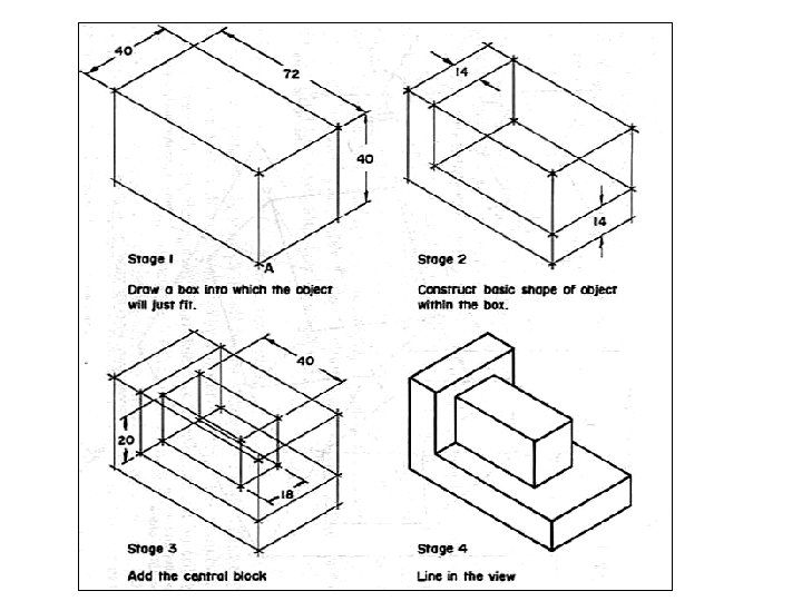
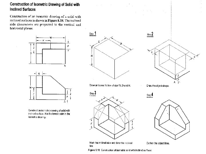
Isometric projection shows all 3 dimensions, length, width and height. The isometric lines are only drawn to scale. 1. Objects composed entirely of isometric lines can be drawn by taking all measurements parallel to main edges of the enclosing box. 2. Non-isometric lines are drawn by transferring the ordinates (which are on isometric lines) of the end of the lines 3. Inclined and oblique surfaces are drawn using end coordinates. Box construction and offset measurements are common methods. 4. In an isometric drawing, an angle never appears in its true size. Angles, irregular curves require special techniques.
The position of the eye with respect to the object is the viewing direction. Viewing direction
Classwork: FV TV FV Make Isometric Drawing for the Front view and Top view given. A A TV FV TV A A
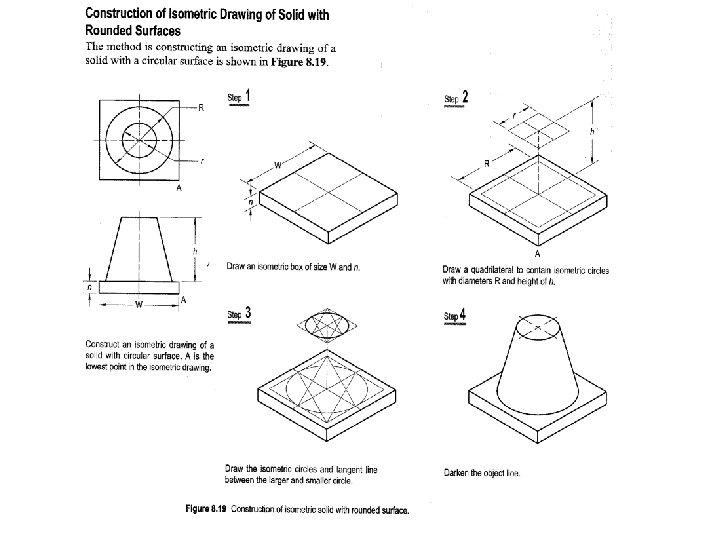
Circles
A A FV TV FV FV TV TV A FV TV A A Make Isometric Drawing for the Front view and Top view given. A HOMEWORK