ISOMETRIC PROJECTIONS AND ISOMETRIC DRAWING Introduction Orthographic view


 Orthographic Projection II) Pictorial Projection III) Pictorial Projection : IV)The")


")
")


 G TH (o n 45 °l")

 Cos 45º = a’m’/AD ----- (2) From (1)")


- Slides: 49
ISOMETRIC PROJECTIONS AND ISOMETRIC DRAWING
Introduction Orthographic view shows only two dimensions in any particular view. This makes it difficult to interpret them and only technically trained person can interpret the meaning of these orthographic views. A non-technical person Can not imagine the shape of the object from orthographic projections. Whereas, pictorial projections can be easily understood even by persons Without any technical training because such views show all the three Dimensions Of an object in the same view.
But pictorial view does not show the true shape and size of any principal surface of An object and it does not show the hidden portions. Pictorial projections are easy to imagine so these are used in sales literature.
q Principle of Projection : If straight lines are drawn from various points of an object to meet a plane then it is said that object is Projected on that plane. q These straight lines from the object to the plane are called projectors. q The figure formed by joining the points at which the projectors meet the plane is called Projection of that object.
Types of Projection: I) Orthographic Projection II) Pictorial Projection III) Pictorial Projection : IV)The projection in which the length , height V) And depth are shown in one view is VI)called Pictorial Projection. VII)Types of Pictorial Projection: VIII)Axonometric IX)Oblique X) Perspective
Axonometric Projection: When projection is obtained on plane inclined to all the three principal planes, then It is called Axonometric projection. Types of Axonometric projection: Isometric Dimetric Trimetric
Isometric Projection : The projection is obtained on a plane which is equally inclined to all the three principal planes. Isometric Projections and Isometric drawings are represented on the plane paper or sheet by drawing isometric axes, isometric lines and isometric planes.
When a cube is kept in particular position then it gives isometric axes, isometric lines and isometric planes. Particular position : When cube is resting on H. P. on corner G and diagonal EC is Perpendicular to A V. P. B D E C F H 30 o M G 30 o N Base Line
Isometric Axes : The three lines CB, CD and CG meeting at the point C and making angle of 120 degree with each other are called isometric axes. Isometric lines: The lines parallel to isometric axes are called isometric lines. Isometric planes: The planes represented by faces of cube are called isometric planes. Similarly any planes parallel to these planes are also called isometric planes.
Isometric drawing or isometric view: The pictorial view drawn with true scale is called Isometric drawing or isometric view. Isometric projection: The pictorial view drawn with the use of isometric scale is called Isometric projection.
F. V. L. H. S. V. X T. V.
H Aim: - Figure-1, shows the F. V. & T. V. of a simple vertical rectangular plane of size L H. Draw its isometric view, for (a) R. H. S. V. & (b) L. H. S. V. b’ a’ d’ a d L F. V. T. V. Figure-1 c’ b c
MN, is the base line for isometric axes. PQ, is the isometric axis (vertical) for Fig. 1(a) H PR, is the isometric axis ( horizontal), for R. H. S. V. for Fig. 1(a) at 30º with base line MN. Q A Note: - The diagonal line R a’c’ in ortho. View B increases in its iso. View D (Fig. 1 -a), as AC (known L as, non isometric line) C X N M Figure-1(a) P
MN, is the base line for isometric axes. PQ, is the isometric axis (vertical) for Fig. 1(b) PS, is the isometric axis ( horizontal), for L. H. S. V. for Fig. 1(b) at 30º with base line MN. Q Note: - The diagonal line a’c’ in ortho. View decreases in its iso. View (Fig. 1 -b), as AC (known as, non isometric line) M B S H A D P C L X Figure-1(b) N
Figure shows the Top View of a rectangular plane of 100 x 70. Draw its isometric view i) for R. H. S. V & ii) for L. H. S. V. b 70 a d 100 T. V. c
70 A 10 0 D X B C 30 ISOMETRIC VIEW OF THE HORIZONTAL RECTANGULAR PLANE (100 X 70) for its R. H. S. V.
B 0 0 1 A C 70 D 30 X 30 ISOMETRIC VIEW OF THE HORIZONTAL RECTANGULAR PLANE (100 X 70) for its L. H. S. V.
d’ c’ c’ M 1 C 2 d’ b’ a’ M 2 C 3 b’ C 1 C 4 N 1 a b a’ N 2 X
ISOMETRIC VIEW OF SIMPLE PLANES Aim: -Figure shows the F. V. of a cut geometric plane. Draw its Isometric view. (i)For R. H. S. V. & (ii)For L. H. S. V. ? b’ c’ a’ d’ H 30 R g’ L f’ F. V. e’
b’ c’ d’ 30 R g’ H A G ? 30 L B C 2 X e’ Now, only the Quadrant of a circle D R 1 F f’ -: Solution : AB=a’ b’ ED=EF=R R R L H Darken the required arc FD with center C 2 a’ ? C 3 C 1 (i) E C 4 C 2 30 (L. H. S. upward), is to be drawn using Four center method.
b’ c’ d’ R g’ L f’ e’ L ? C B D A E 30 H a’ ? F G 30 (ii) X
Aim: -Figure shows the T. V. of a cut geometric plane. Draw its Isometric, (i)For R. H. S. V. & (ii) For L. H. S. V. b ? d c e R D f 30 j a D 1 45 L 1 i k L T. V. h 45 L 2 g
? b c d R D f j 45 a L 1 i D 1 30 k 45 L T. V. h BC=bc= ? e L 2 B ED=EF=R AK=ak=L 1 GH=gh=L 2 Draw, J I // AG ( at a distance of D 1 ) g ? D 30 A JM 45 L 1 1 D K N L I H L 45 2 X G (i) Note : - (1) MJ=KM=D 1, as angle jka=45 (2) Angle JKA & Angle IHG are not C 45 in isometric. D R F 30 E
d c D R j 45 a L 1 i D 1 30 k L T. V. h C ? B 45 L 2 AK=ak=L 1 f Draw, J I // AG ( at a distance of D 1 ) g E D Note : - M J 30 45 1 K L A D 1 D BC=bc= ? e R ? b 30 (ii) (1) MJ=KM=D 1, as angle jka=45 F (2) Angle JKA & I 45 G Angle IHG are N L 2 not 45 in H isometric. L X
C 3’ C 2’ c’ M 1 C 4’ T. V. C 2 d’ M 2 C 3 C 4 N 1 a’ F. V. N 2 b’ C 1 X
X a’ e’ 90° s b’ c’ d’ d r Y Draw the Iso. View of a regular Pentagonal plane of 40 mm sides, with one side normal to V. P. & the plane is in H. P. e 40 g a c b p 2 D R D q S C G E Q B 40 A P 3 D X
a’ g’ b’ c’ d’ e’ d e 40 X O g Draw the Iso. View of a Pentagonal Pyramid, having base sides 40 mm, axis 60 mm Y long, when its base is in H. P. with a side of it normal to V. P. O 60 60 O’ c R a D b 2 D S C G E 40 Q B A P 3 D X
Aim: - Figure shows the orthographic projections of a cut simple block. Draw its appropriate Pictorial ( Isometric ) view, giving the dimensions. NOTE: The appropriate Isometric will be, considering its R. H. S. V. ( which is not given & is to be added as a missed view).
55 a B b 55 R. H. S. V. Figure 30 2 1 55 20 Normally, dotted lines are not drawn in Iso. View, unless specifically required to reveal the object perfectly. d c 60 F. V. 15 20 A 3 15 15 T. V.
60 A a F. V. 2 1 3 b 15 15 T. V. 15 X c 30 15 ISOMETRIC VIEW 20 40 1 30 2 35 20 30 d c 15 b 55 55 a 15 20 20 3 d B 55 NOTE: - IN R. H. S. MISSED VIEW, THE AREAS, A & B ARE SEEN AND IS DRAWN IN ITS CORROSPONDING SPACE
Figure shows Front View and Top View of a machine parts. Sketch its isometric view & dimension it.
SQ. HOLE OF 20 R 25 C B 20 D 30 70 A 30° 20 F. V. a 20 10 20 b 2 c 10 b 1 70 T. V. 20
ISOMETRIC VIEW SQ. HOLE OF 20 25 a 10 95 C B b 2 30° b 1 D 20 11 5 X 20 20 25 30 A c 20 50
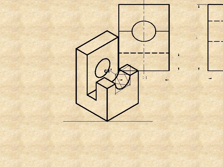
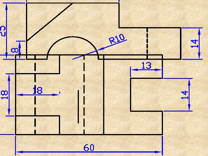
Aim: - Figure shows the F. V. & T. V. of a machine component. 20 Figure 15 F. V. the dimensions. 15 30 20 R 10 15 view, giving 30 (ISOMETRIC) 120 T. V. 20 pictorial 0 R 3 Draw its 40
Note 1: - The machine component is splitted into four different parts, for its iso. sketching, with bottom base part as first drawn. Note 2: -The circularity or part of that of Ortho. View, is to be drawn in Iso view as an ellipse or part of that using “four center method”, as explained earlier. Note 3: - Such components may be drawn in iso. , by area (plane)wise w. r. t F. V, T. V & S. V directions. Never prefer “box method” for such components.
20 60 Split-II Solution Split-III 20 15 R 3 0 See, Note 2 30 30 15 R 1 20 Split-IV 15 65 ISOMETRIC VIEW 20 See, Note 2 0 0 2 1 Split-I
ISOMETRIC SCALE (To be used for isometric projections) G TH (o n 45 °l in e) 70 50 40 30 ) e in C TU A L LE N l ° 0 20 3 (on ) 10 60 TH √ 3 G 2/ P N 0 LE Y √ 40 C B -5 I R D T CE -10 E 20 M DU O IS (RE Q 45° B 90° 30° A A 60 BASE LINE
III. A The Front View of the Top Face of a Cube having edges “e” (with one of the body diagonal line, normal to V. P. ) is to be treated D as ISOMETRIC of the Top Face of the Cube d’ (with a side parallel to V. P. ) 45° 30° m’ C All the edges Top face A c’ a’ M edges, base face edges and 4 vertical edges of the cube are reduced in b’ its isometric view, in a’d’= f (AD) the stated condition. B
Cos 30º = a’m’/a’d’ ----- (1) Cos 45º = a’m’/AD ----- (2) From (1) & (2) a’m’ = a’d’ cos 30º = AD cos 45º D i. e. a’d’ = AD cos 45º/cos 30 d’ A a’ 30° 45° m’ M b’ a’d’= f (AD) B C c’ e x 1/ 2 = 3/2 i. e. a’d’ = AD x 2/3 i. e. ISOMETRIC LENGTH = (0. 815 x ACTUAL LENGTH)
Aim: - Sketch shows the Orthographic views of a machine component. Draw its appropriate Isometric view, using “splitting the object into pieces” techniques. Give the dimensions on the ISOMETRIC VIEW drawn.
R 40 Sketch 20 30 40 20 20 90 50 10 T. V. 40 20 80 30 F. V. R. H. S. V. (missed view) may be added here in height & depth range
30 25 50 C 20 10 Dimensions must be given on the Isometric view, which are not shown here. 30 50 20 40 20 B 80 20 70 Ø 30 90 20 R 15 25 25 A 20 R 40 80 x 80 square D
Exercise Figure shows the Orthographic views of a machine component. Draw its Isometric view. Give the dimensions as per aligned system.
R 30 c 60 40 80 L. H. S. V. B 15 60 15 20 40 b a 35 25 10 Ø 30 A 120 FRONT VIEW FIGURE NOTE: - The front view areas are A & B, while the side view areas are a, b & c.
Solution ø 30 R 30 c 20 15 35 25 B 60 20 15 10 20 40 ISOMETRIC VIEW a 4 80 0 b A 0 2 1 X
F. V. L. H. S. V.
34 60 25 L= 60 mm H= 25 mm D= 34 mm X