ISL David Stuart UC Santa Barbara May 11

ISL David Stuart, UC Santa Barbara May 11, 2006

ISL Formerly known as Intermediate Radius Silicon David Stuart, UC Santa Barbara May 11, 2006

I’ll review the motivation for the detector and give a tour of its design and construction

The motivation is best shown by looking at an event display from Run 1.

The motivation is best shown by looking at an event display from Run 1.

The motivation is best shown by looking at an event display from Run 1. Tracks are obviously missed and obviously easy to find.

Actual size

Unused hits from: 1. Low p. T 2. > 1

Using forward silicon hits in Run 1 1. Stand-alone silicon pattern recognition • Fit for f 0, d 0, p. T (curvature) with 4 hits, <=1 dof. • It worked, but was limited by • lever arm (L 2) • Too few hits • Poor curvature resolution degraded impact parameter resolution • 4% relative increase in b-tagging for top

Using forward silicon hits in Run 1 2. Calorimeter-seeded tracking for electrons i. e. , Phoenix eegg. ET event

eegg. ET event
")
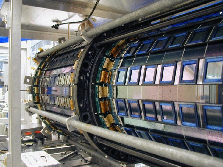
ISL designed to extend lever arm ISL SVXII L 00 SVX’ (Run 1)

Design goals Fine granularity at large radius for Low occupancy typical jet has ~10 tracks in a Df<0. 2 cone, covers 1000 channels Resolution and lever arm (BL 2) 100 m pitch = 30 m resolution sufficient for Negligible effect on d 0 resolution Pointing into COT < hit resolution at high p. T < hit width at low p. T COT res 2 trk

Portcard scattering is a real complication
 Cheap Fast")
Design requirements Big (5 m 2) Cheap Fast
 simple Cheap simple Fast simple Piggybacking on SVX-II")
Design requirements Big (5 m 2) simple Cheap simple Fast simple Piggybacking on SVX-II infrastructure important

Sensor Design Big- used max possible sensor size per wafer. HPK only had 4” wafers Micron had 6”, and they were cheaper (in both senses of the word). Layer 6 built with HPK at Fermilab Layer 7 built with Micron at Pisa Different geometries, mechanics, & quality
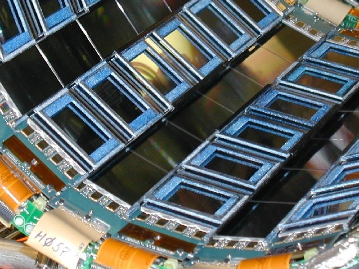
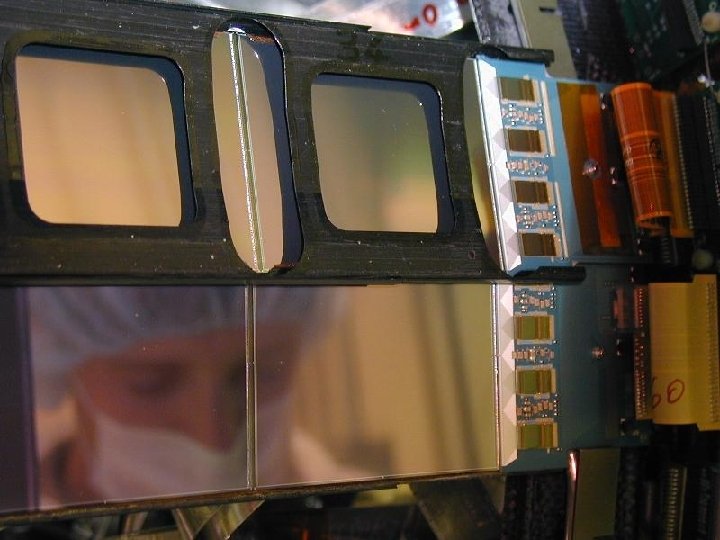

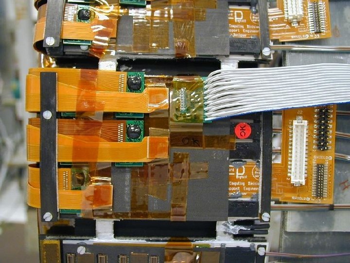
Readout Hybrid Double sided and spacious Pitch adapter Transceiver

Half ladder

Full ladder

Ganging Not in trigger, but don’t preclude, so r-phi read first. 16 chips total--max FIB can handle. Note up-down reverses hall effect and readout direction.

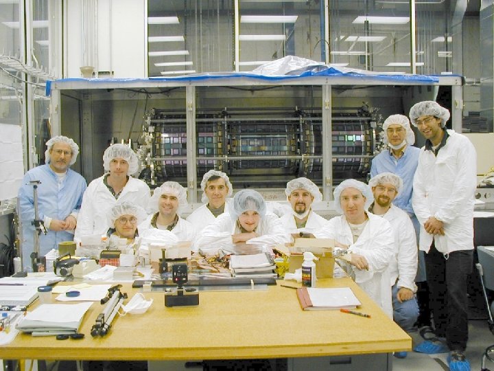
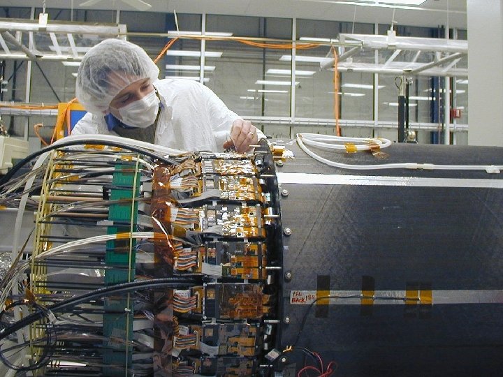
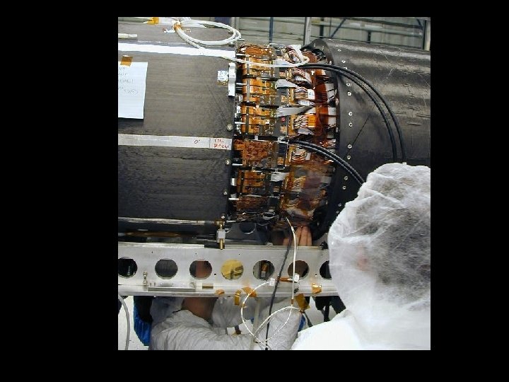
Joel dropped them in place

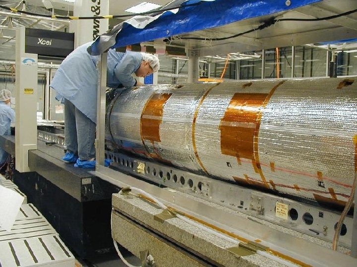
Supported by carbon fiber spaceframe Containing cable and cooling and gang card mounts

Notable differences from SVXII • Because rad damage is less of a concern, and no direct silicon heating – ISL operates ~10 deg warmer than SVXII • Layer 6 has the implant on the z-side • IB 0, 1, 4, 5 (forward region) – L 0, L 2, L 4 are layer seven (Micron sensors) – L 1, L 3 are layer six (Hamamatsu sensors) • IB 2, 3 (central region) – Everything is layer six • Within a given layer, IBx. Wy. Lz, y and z denote phi position of ganged readout pair

Recall Design goals • Forward tracking

Recall Design goals • Forward tracking ?
- Slides: 34