ISIS Second Target Station Project Summary Target design


![Pressure [Pa] Vapour Pressure H 20](https://slidetodoc.com/presentation_image/0f822ca859e2a0ae748f16440e28a512/image-15.jpg "Pressure [Pa] Vapour Pressure H 20")


- Slides: 22
ISIS Second Target Station Project Summary Target design, analysis and optimisation Robbie Scott Mechanical Design / Project Engineer ISIS Facility
ISIS Second Target Station • Upgrade of ISIS – accelerator based, pulsed neutron source • Synchrotron accelerator shared between both target stations • Double the number of instruments
ISIS Second Target Station • Designed for key future scientific needs: • • Soft matter Advanced materials Bio-molecular science Nano-technology • Scientific requirements imply need for specific flux characteristics: • Significantly enhanced cold neutron flux • Broad spectral range • High resolution • Moderators designed to provide excellent conditions for required flux characteristics: • • Low frequency : • 10 Hz • 100 ms frame Low power: • 48 k. W • 60µA } } Wide dynamic range Optimised for cold neutron production
Neutronically efficient target design • Maximise use of ‘target’ materials • Design target geometry to match proton beam • Maximises target neutron yield, while minimising absorption • Optimise cross-sectional area • Minimise volume of coolant channels • Maximises solid angle which moderators view
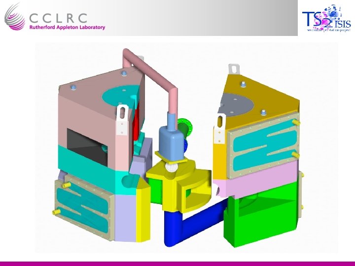
Baseline target design Flow Divider Tungsten Core D 20 Out EPB Proton beam window D 20 in Stainless Steel Pressure Vessel D 20 Tantalum Cladding
Optimisation of baseline target design • Reduction in pressure vessel wall by 70% • Reduction in coolant channel depth by 80% • Overall reduction in Target diameter of 28% • Allows moderators to move closer to neutron producing core • Increases solid angle which moderators view • Reduces probability of neutron absorption within target • Resulted in significant increases in neutron flux (60%)
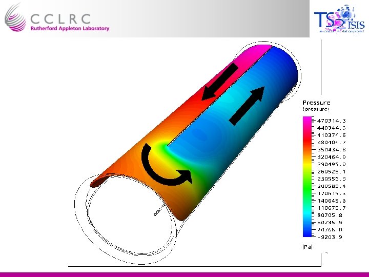
Back to the drawing board! • Removal of proton beam window & introduction of new cooling channel concept • Proton beam no longer passes through Inconel window and D 20 • Flow channel geometry altered – purely radial cooling • Flux increase of approximately 5% • Improved reliability Pressure distribution within target cooling channels
Materials • Pressure vessel material choice • Replace stainless steel with Tantalum • Further reductions in target diameter (now 63% of original size) • Further 15% flux increase
Consequences of design alterations • Total predicted flux increase due to design alterations ≈ 75 - 80% • Neutron flux 95% of pure Tungsten target • However new cooling channel concept must be proven • Computational Fluid Dynamics (CFD) employed for analysis and optimisation of coolant channels • CFD subsequently verified using flow tests
CFD Analysis of initial design • CFX used to Computational Fluid Dynamics analysis • CFD revealed problematic separation & pressure drop at inside of bend • Resulting recirculation would heat coolant excessively
Removal of recirculation • A solution was required to remove the recirculation • The flow guide was modified into an aerofoil form • Prevents separation and subsequent recirculation
Cavitation • A fluid’s vapour pressure is proportional to temperature • If the pressure within a flow falls below the local vapour pressure, cavities (or bubbles) will form • As the cavities leave the low pressure region, they collapse, damaging the vessel wall 2. 4 bar 1 0 -0. 7
Pressure [Pa] Vapour Pressure H 20
Cavitation Prevention • High flow velocities within the target cause a pressure drop on the inside of the bend • If local vapour pressure is greater than local pressure, cavitation will occur • Solution • Map vapour pressure onto flow model • Increase inlet and outlet pressures (maintaining differential) until pressure in all regions are above local vapour pressure • Final inlet pressure 5 bar
Modelling proton beam heat load within the target • MCNPX used to calculate energy deposition by the proton beam within target • Curve fitting allowed the creation of functions which accurately describe the axial and radial variation of heat load [K]
Thermally induced stress • Temperatures within target are calculated using CFD • Temperatures exported to an FEA package (ANSYS) • Thermally induced expansions are then calculated • Resultant stresses and are then calculated • Differing coefficient of thermal expansion • Tungsten & Tantalum differ by 2µm/m/°C • Small stresses
Verifying CFD Results • Prototype thermal test target, installed with a dense network of pressure tappings • 5 cartridge heaters will supply 37 k. W of power, to test the cooling • Power varied axially along the target
Manufacturing • Majority of target simple to manufacture: • Tungsten core is encased in a 1 mm sleeve of Tantalum • Sleeve is e-beam welded, creating a hermetic seal • Assembly is hot isostatically pressed (HIP) • Ultrasonic NDT used to test HIP bond
• Tantalum pressure vessel complex to manufacture • Incorporates aerofoil structures on ID! • Former created on CNC mill • Hot Isostatic Pressing is used to create the vessel from powder • Former leached away after vessel created • Pressure vessel shrink fitted onto then assembly e-beam welded core,
Project Uncertainties • Potential for erosion due to high coolant velocities • Pressure vessel manufacturing method yet to be proven