
ISDN Lecture 5 Paul Flynn 1 Functional Architecture
- Slides: 32
ISDN Lecture 5 Paul Flynn 1
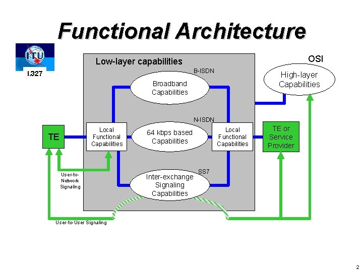
Functional Architecture OSI Low-layer capabilities B-ISDN I. 327 High-layer Capabilities Broadband Capabilities N-ISDN Local Functional Capabilities TE User-to. Network Signaling Local Functional Capabilities 64 kbps based Capabilities Inter-exchange Signaling Capabilities TE or Service Provider SS 7 User-to-User Signaling 2
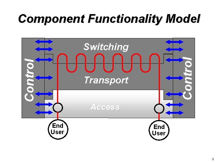
Component Functionality Model Control Switching Transport Access End User 3
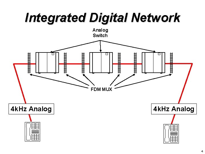
Integrated Digital Network Analog Switch FDM MUX 4 k. Hz Analog 4
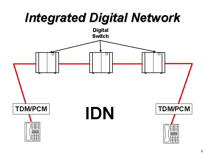
Integrated Digital Network Digital Switch TDM/PCM IDN TDM/PCM 5
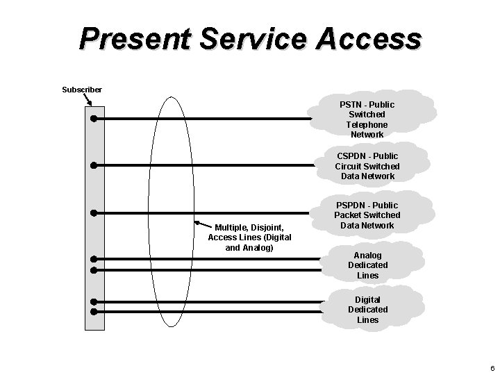
Present Service Access Subscriber PSTN - Public Switched Telephone Network CSPDN - Public Circuit Switched Data Network Multiple, Disjoint, Access Lines (Digital and Analog) PSPDN - Public Packet Switched Data Network Analog Dedicated Lines Digital Dedicated Lines 6
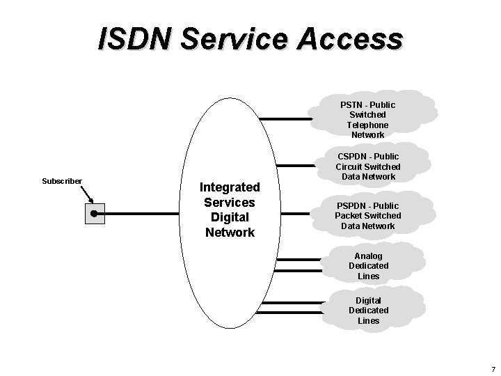
ISDN Service Access PSTN - Public Switched Telephone Network Subscriber Integrated Services Digital Network CSPDN - Public Circuit Switched Data Network PSPDN - Public Packet Switched Data Network Analog Dedicated Lines Digital Dedicated Lines 7
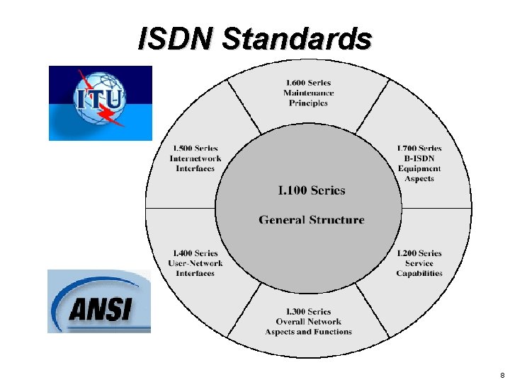
ISDN Standards 8
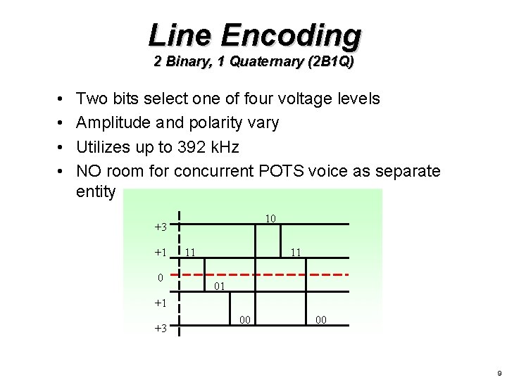
Line Encoding 2 Binary, 1 Quaternary (2 B 1 Q) • • Two bits select one of four voltage levels Amplitude and polarity vary Utilizes up to 392 k. Hz NO room for concurrent POTS voice as separate entity 10 +3 +1 0 11 11 01 +1 +3 00 00 9
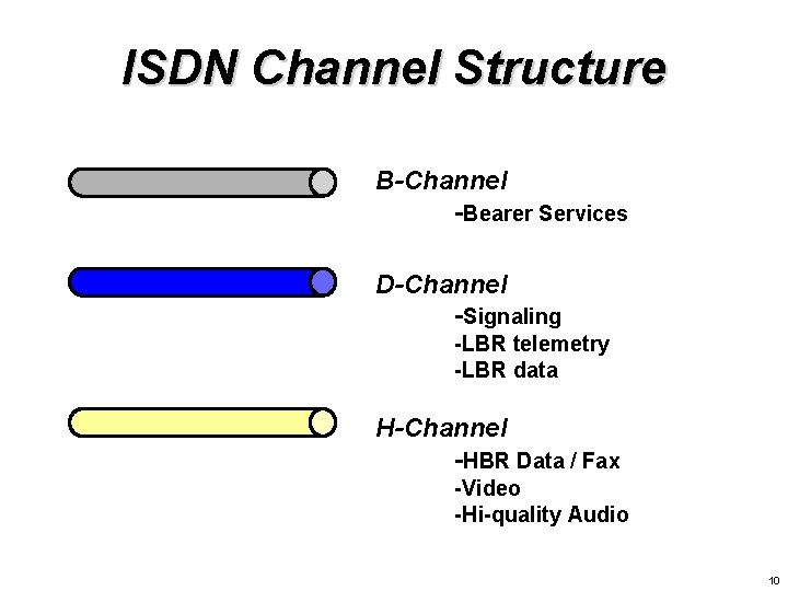
ISDN Channel Structure B-Channel -Bearer Services D-Channel -Signaling -LBR telemetry -LBR data H-Channel -HBR Data / Fax -Video -Hi-quality Audio 10
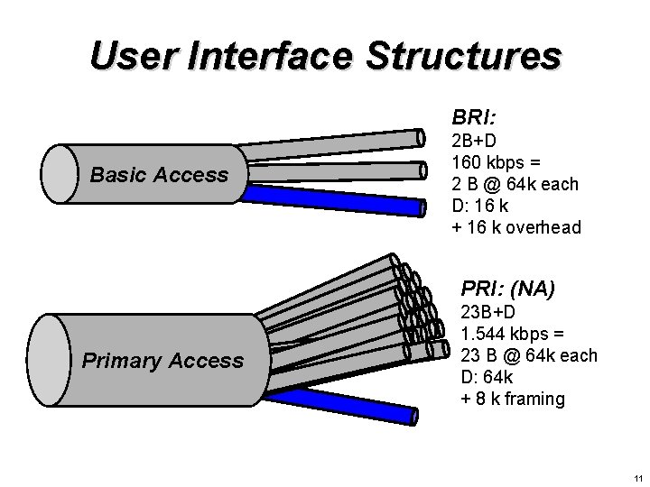
User Interface Structures BRI: Basic Access 2 B+D 160 kbps = 2 B @ 64 k each D: 16 k + 16 k overhead PRI: (NA) Primary Access 23 B+D 1. 544 kbps = 23 B @ 64 k each D: 64 k + 8 k framing 11
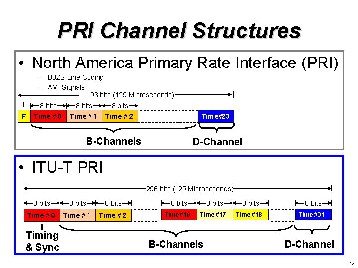
PRI Channel Structures • North America Primary Rate Interface (PRI) – B 8 ZS Line Coding – AMI Signals 193 bits (125 Microseconds) 1 F 8 bits Time # 0 8 bits Time # 1 8 bits Time # 2 Time#23 B-Channels D-Channel • ITU-T PRI 256 bits (125 Microseconds) 8 bits 8 bits Time # 0 Time # 1 Time # 2 Time #16 Time #17 Time #18 Time #31 Timing & Sync B-Channels D-Channel 12
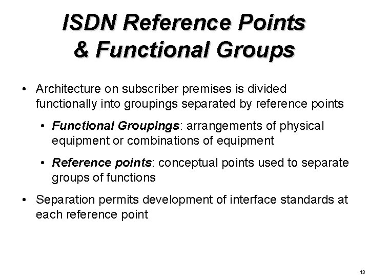
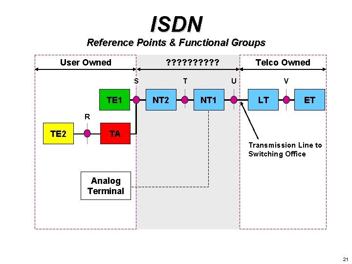
ISDN Reference Points & Functional Groups • Architecture on subscriber premises is divided functionally into groupings separated by reference points • Functional Groupings: arrangements of physical equipment or combinations of equipment • Reference points: conceptual points used to separate groups of functions • Separation permits development of interface standards at each reference point 13
Integrated Services Bus Network (ISBN) 14
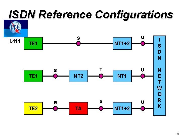
ISDN Reference Configurations I. 411 S TE 1 I S D N U N E T W O R K NT 1+2 T S TE 1 NT 2 NT 1 S R TE 2 U TA U NT 1+2 15
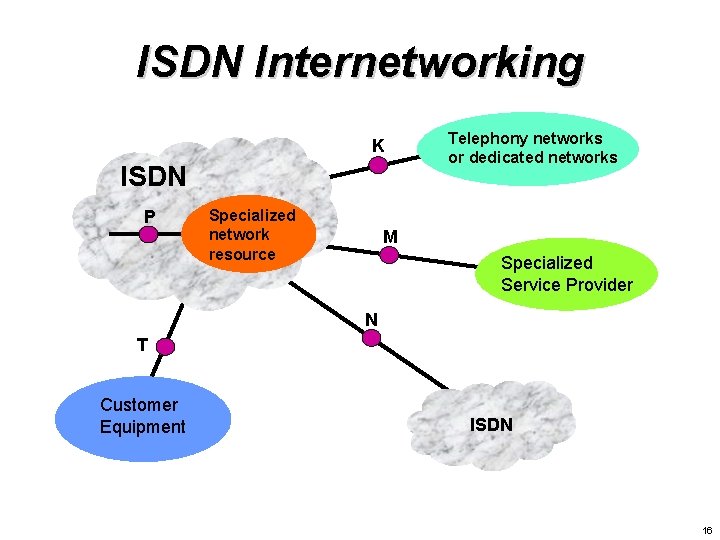
ISDN Internetworking K ISDN P Specialized network resource Telephony networks or dedicated networks M Specialized Service Provider N T Customer Equipment ISDN 16
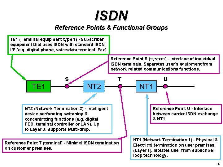
ISDN Reference Points & Functional Groups TE 1 (Terminal equipment type 1) - Subscriber equipment that uses ISDN with standard ISDN I/F (e. g. digital phone, voice/data terminal, Fax) Reference Point S (system) - Interface of individual ISDN terminals. Separates user’s equipment from network related communications functions. S TE 1 T NT 2 (Network Termination 2) - Intelligent device performing switching & concentrating functions (e. g. digital PBX, terminal controller or LAN). Up to Layer 3. Supports Multi-drop. Reference Point T (terminal) - Minimal ISDN termination on customer premises. U NT 1 Reference Point U - Interface between carrier ISDN exchange & NT 1 (Network Termination 1) - Physical & Electrical termination on user premises (Layer 1). Isolates user from subscriber loop technology. 17
The U-Interface G. 961, Digital Transmission System for Metallic Local Lines for ISDN Basic Rate Access, 1993 ANSI T 1. 601, Integrated Services Digital Network – Basic Access Interface for Use on Metallic Loops for Application on the Network Side of the NT, 1992 18
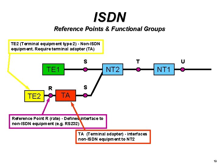
ISDN Reference Points & Functional Groups TE 2 (Terminal equipment type 2) - Non-ISDN equipment. Require terminal adapter (TA) S TE 1 R TE 2 T NT 2 U NT 1 S TA Reference Point R (rate) - Defines interface to non-ISDN equipment (e. g. RS 232) TA (Terminal adapter) - interfaces non-ISDN equipment to NT 2 19
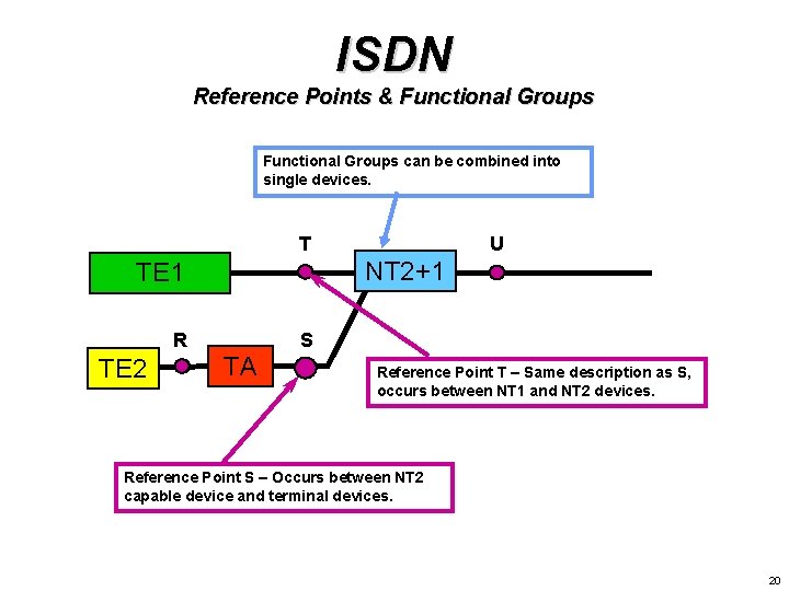
ISDN Reference Points & Functional Groups can be combined into single devices. T NT 2+1 TE 1 R TE 2 U S TA Reference Point T – Same description as S, occurs between NT 1 and NT 2 devices. Reference Point S – Occurs between NT 2 capable device and terminal devices. 20
ISDN Reference Points & Functional Groups User Owned ? ? ? ? ? S TE 1 T NT 2 Telco Owned U NT 1 V LT ET R TE 2 TA Transmission Line to Switching Office Analog Terminal 21
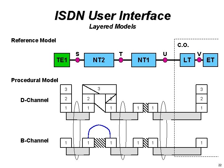
ISDN User Interface Layered Models Reference Model C. O. TE 1 S T NT 2 U NT 1 LT V ET Procedural Model 3 3 D-Channel B-Channel 3 2 2 1 1 1 22
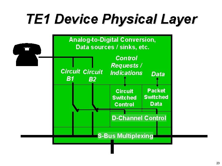
TE 1 Device Physical Layer ( Analog-to-Digital Conversion, Data sources / sinks, etc. Circuit B 1 B 2 Control Requests / Indications Circuit Switched Control Data Packet Switched Data D-Channel Control S-Bus Multiplexing 23
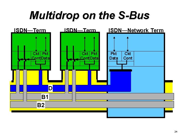
Multidrop on the S-Bus ISDN—Term Ckt Pkt Cont Data ISDN—Network Term Pkt Data Ckt Cont D B 1 B 2 24
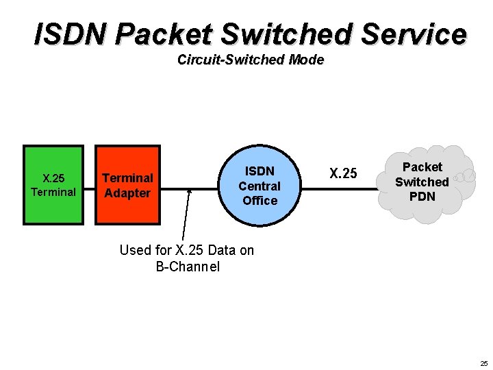
ISDN Packet Switched Service Circuit-Switched Mode X. 25 Terminal Adapter ISDN Central Office X. 25 Packet Switched PDN Used for X. 25 Data on B-Channel 25
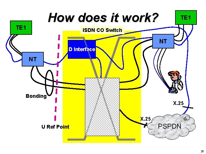
How does it work? TE 1 ISDN CO Switch NT D Interface NT Bonding X. 25 U Ref Point PSPDN 26
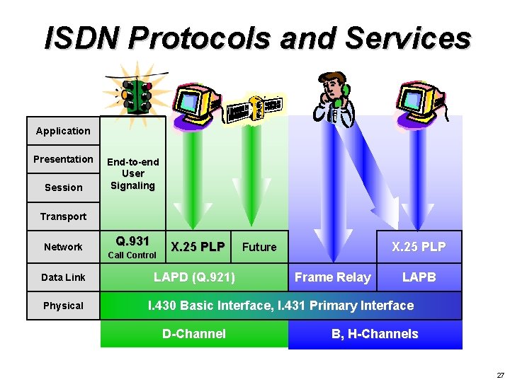
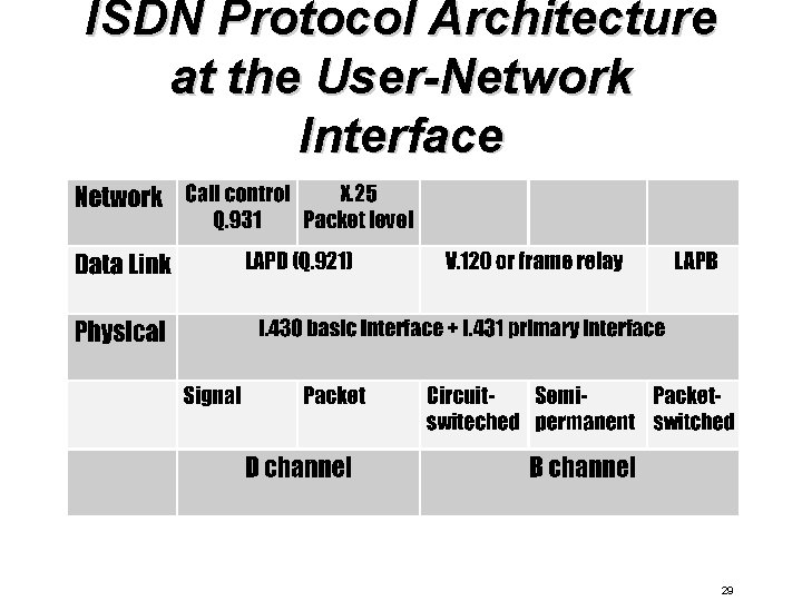
ISDN Protocols and Services Application Presentation Session End-to-end User Signaling Transport Network Data Link Physical Q. 931 Call Control X. 25 PLP LAPD (Q. 921) X. 25 PLP Future Frame Relay LAPB I. 430 Basic Interface, I. 431 Primary Interface D-Channel B, H-Channels 27
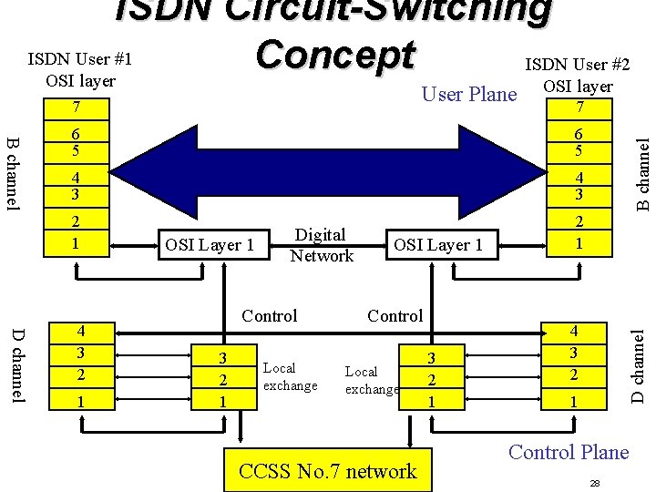
ISDN Circuit-Switching ISDN User #1 Concept ISDN User #2 OSI layer 7 B channel 6 5 4 3 2 1 D channel 4 3 2 1 OSI Layer 1 Digital Network Control 3 2 1 Local exchange OSI Layer 1 Control Local exchange CCSS No. 7 network 3 2 1 4 3 2 D channel 7 OSI layer B channel User Plane 1 Control Plane 28
ISDN Protocol Architecture at the User-Network Interface 29
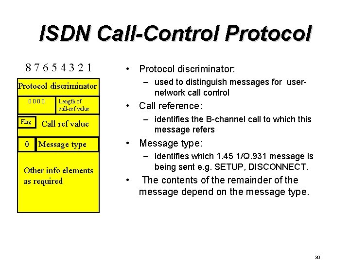
ISDN Call-Control Protocol 87654321 • Protocol discriminator: – used to distinguish messages for usernetwork call control Protocol discriminator 0000 Flag 0 Length of call-ref value • Call reference: – identifies the B-channel call to which this message refers Call ref value Message type Other info elements as required • Message type: – identifies which 1. 45 1/Q. 931 message is being sent e. g. SETUP, DISCONNECT. • The contents of the remainder of the message depend on the message type. 30
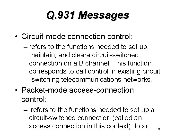
Q. 931 Messages • Circuit-mode connection control: – refers to the functions needed to set up, maintain, and cleara circuit-switched connection on a B channel. This function corresponds to call control in existing circuit -switching telecommunications networks. • Packet-mode access-connection control: – refers to the functions needed to set up a circuit-switched connection (called an access connection in this context) to an 31
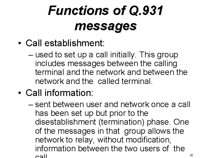
Functions of Q. 931 messages • Call establishment: – used to set up a call initially. This group includes messages between the calling terminal and the network and between the network and the called terminal. • Call information: – sent between user and network once a call has been set up but prior to the disestablishment (termination) phase. One of the messages in that group allows the network to relay, without modification, information between the two users of the 32