ISASP 100 11 a DLL Superframes graphs and


 into an 802. 15. 4 channel")


 • • • A mote has a packet with")


 Length 1 Tag 1 Header Tag 1")


 A CCA: RX startup, listen, RX->TX B")


- Slides: 50
ISA-SP 100. 11 a DLL Superframes, graphs, and mixed TDMA/CSMA K. Pister, UC Berkeley This document is provided strictly for the purpose of gathering information leading to the development of an ISA standard, recommended practice or technical report. Copies may be reproduced and distributed, in whole or in part, but only for the following purposes: Review of and comment on the ISA-SP 100 draft proposal Submission to ISA-SP 100 Committee Informing and educating others about the ISA-SP 100 draft standard development process. Standards Certification Education & Training Publishing Copyright © 2007 by ISA – all rights reserved Conferences & Exhibits 1
Network Device 37 A network device is identified by a single number Network device is either a mote or GW A network is composed of a collection of N network devices
Path 37 53 A path is a pair of network devices A path has no direction Paths do not necessarily have communication capability on them, but we only keep track of paths that have been discovered could be used for communication
Connection 53 receiver 37 sender A connection is : A sender ID + a receiver ID + a graph ID This connection = [37, 53, blue] Can also be thought of as a path ID + direction + graph ID A connection represents routing A connection may or may not have links using it
Link 53 37 A link defines a timeslot and channel offset. A link consumes capacity. Links are directional. Links are associated with graphs. This is the link that uses the blue graph connection from 37 to 53 on slot 4 and offset 7
Link types one destination > one • Contention free one source • Collisions possible > one • Unicast • Acknowledged • Broadcast • No ACK
Graph 17 47 53 37 41 43 A graph is a collection of connections and the links belonging to them A graph is both routing and capacity In our implementation, the connections cannot form loops Graphs are activated and deactivated by a management function Similar to ATM circuits and Cisco tag switching (MPLS)
Superframe • A superframe is a collection of slots that repeat periodically in cycles • Binds/implements links from a graph with specific time/channel offset Superframe Unallocated Slot Allocated Slot
Time Slot and Channel Mapping D Time One Slot Chan. offset A B A C B D A B A Slot links for devices • The two links from B to A are dedicated • D and C share a link for transmitting to A • The shared link does not collide with the dedicated links
802. 15. 4 Slot and superframe timing • Slot length – When SO = 0 60 symbols 0. 96 ms • Active superframe duration – 16 slots 15. 36 ms when SO=0 • Superframe duration – 15. 36 ms * 2 BO ; BO = 0. . 14 – Up to 4 minutes (> 250, 000 slots) Semi-active Channel-hopping 16|17|18|19|20|21|22|23|24|25|26|27|28|…
Channel Hopping • Need to map (slot, offset) into an 802. 15. 4 channel – For blacklisting, assume – Num_channels – Look. Up defines pseudo-random hop sequence over num_channels • ASN = absolute slot number • Chan = (ASN + offset) % num_channels • 15. 4 Channel = Look. Up(Chan)
Non-conflicting cell assignment • Routers can be given one or more offsets. OR • Routers can be given one or more slots in a particular superframe. OR • Routers can be given a block of (slot, offset)s slot Chan. offset
Non-conflicting cell assignment • Routers can be given one or more offsets. OR • Routers can be given one or more slots in a particular superframe. OR • Routers can be given a block of (slot, offset)s
Non-conflicting cell assignment • Multiple superframes with different lengths can operate without conflict as well. • 4 cycles of the 250 ms frame are shown, along with one that is 1 s long • There are never collisions if the 1 second frame uses only the empty slots 250 ms 1, 000 ms
CSMA slots/subframes • To reserve 4 slots in a row: – – – (s, r) (s+1, r-1) (s+2, r-2) (s+3, r-3) This way it will all be on the same channel and messages can flow uninterrupted
A CSMA frame Copyright © 2007 by ISA – all rights reserved 16
Local Link Use (Graph Routing) • • • A mote has a packet with Graph = blue in its queue Forms list {blue receivers} for this node Any link on any connection that comes up on a TX slot for this mote can be used providing the receiver is in {blue receivers} – Does not matter which graph is used – Both graphs must have appropriate “share resources” bits set
Example 1 17 47 41 53 37 43 Packet generated at 37 with blue graph ID @37, can go on blue to 47 or blue/red to 53, cannot go on red to 43 @53, must go on blue to 17 @47, must go on blue to 17 There are two routes from 37 to 17: (A) 37 53 17 (B) 37 47 17
Low latency – immediate retransmissions • • Dedicated bandwidth for first k transmissions Shared bandwidth for next j All transmissions are on different channels DR = 1 -PERk+j
Low latency – multiple hops • Color indicates TX slot for mote of that color • 5 hops = 5 slots = 50 ms • Can repeat immediately, or every k slots, according to superframe length. • Peak throughput with n motes in a line: 1 payload / (n*10 ms) = 100/n payloads/second
High throughput – multiple hops • Use multiple channels • Only need 2 time slots • Throughput is 50 packets/second – independent of n Odd slots Even slots Odd slots
Blacklisting • Network based – Manager builds entire network based on a fixed set of channels • Superframe based – Superframes have an associated blacklist. This can leave only a single frequency if desired. – Blacklist is transmitted as a part of the advertising packet sent as a bitmap
Powered Routers • Slotted Aloha – Single slot superframe, with both RX and TX slot. Use TX if you’ve got something to send, otherwise RX – (10 ms)/PDR per hop Aloha • Dedicated BW (example) – 2 slot superframe; even RX, odd TX – 50 packets/second throughput – >32 kbps payload goodput Tx, Rx
Backbone routers • CSMA – ~25 kbps non-collision payload goodput max – Potential for chaotic collapse near that limit – Potential for long term (>> 10 ms) channel jamming • Slotted Aloha – ~37 non-collision packets/sec max • Dedicated BW – – 100 packets/sec 64 kbps payload goodput >50% channel utilization (full packet + ACK) Deterministic within PER limits
Joining • Active – Wakeup and say hello on k channels, n times – Hope for powered infrastructure, CSMA slots – Then… • Passive – Listen until you hear an advertisement (possibly piggybacked on another packet) – Transition to low duty cycle listening if you want to – Tsynch = CT/(PD) – C = number of channels – T = mean time between packets that you could hear if you were listening on the right channel – P packet deliver rate – D = duty cycle of receiver
K-Cast Timing Radio turnaroud Child TX ACK phase Timing: Who is transmitting? If dark teal parent ACKs, child turns off receiver following dark teal phase If moss parent ACKs, child turns off receiver following moss phase, etc. You want your best parent to come first, best in terms of stability All this happens on a single channel, so it takes up no more BW than usual
K-slotlet CSMA Timing Radio turnaroud CS/TX start ACK Examples: Multiple CSMA slotlets for carrier sense. Can be assigned deterministically or chosen randomly. Works well if everyone can hear everyone else.
Packet format overview 802. 15. 4 Length Mac Header Net header Transport header 1 7+ 6+ 2+ Application payload Mac MIC 802. 15. 4 FCS 4 2
MAC Layer Control Dest Addr Src Addr Network Id Optional Data 1 2/8 2 0+ Control Field contents 0 Data / Ack 1 Short/Long destination address 2 Short/Long source address 3 -4 Protocol type 5 Optional data present 6 -7 Reserved (set to 0) Optional data usage: • advertisements • destination net id • future extensions
Net Layer Control Dest Address Source Address TTL Optional Data 1 2 2 1 0+ Control 0 -1 Packet priority 0=net mgmt priority, 1 -3: user priorities 2 -4 Protocol type 0: reliable unicast 1: reliable broadcast 2: best effort 3 -7: reserved 5 -7 Reserved, set to 0
‘Optional Data’ format (MAC & NET headers) Length 1 Tag 1 Header Tag 1 Data 1 1 -32 Tag Header format 0 -2 Tag Id (0 -7) 3 -7 Length Of Tag Data (1 -32) Tag N Header Tag N Data 1 1 -32
Transport Layers Others ? Reliable Unicast Control Sequential Number 1 1 Control 4 -7 Group id 5 Request/Response 6 Application Ack request Best effort
Size of headers MAC 7 -19 bytes NOpt. MAC bytes for advertisement and optional data Net 6 bytes NOpt. Net bytes for route and optional data Transport 2 bytes 1 byte for additional sequential number Application 2 bytes Summary 17 + NOpt. MAC + NOpt. Net (short MAC addresses) 21 + NOpt. MAC + NOpt. Net (mix MAC addresses) 29 + NOpt. MAC + NOpt. Net (long MAC addresses) (today length of MAC+Net Headers are 31 bytes)
Points to cover • • • ASN-based hopping, allocation of blocks to routers Pure CSMA Mixed tdma/csma Mixed centralized and distributed slot allocation Benefits of slotted aloha over csma Similarity of graphs to ATM, MPLS Keepalives and heartbeat Per-frame and per-path blacklisting Per-frame slot length Don’t do randomized csma slots – do synchronized to avoid all collisions 15. 4 beacon enabled Active vs. passive joining – Joining time; mixed: active first, then passive • • Throughput advantage of tdma Dedicated slots followed by shared slots (slotted aloha, not csma) for N children Lowest power: “data ready” on ack, slotted aloha upstream in every slot if desired Powered routers 34
Additional Slides
Path Statistics • We would like to have statistics collected by path – – TX attempts (as reported by sender) TX fails (no ack was received at sender) RX good (ack OR nack sent by receiver) RX bad (packet has bad CRC at receiver) • These must be reported for both directions on the path (37 53) and (53 37) • This information is a summary of connections from all graphs on this path
Scalability: Outdoor Test Network 1, 100 m -1400 Motes -20 Managers - 32 Acres 600 m ~10 mote-centuries
50 motes, 7 hops 3 floors, 150, 000 sf >100, 000 packets/day
Oil Refinery – Double Coker Unit • • • GW • 400 m Scope limited to Coker facility and support units spanning over 1200 ft No repeaters were needed to ensure connectivity Electrical/Mechanical contractor installed per wired practices >5 year life on C-cell
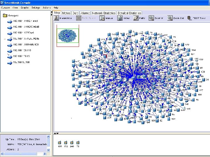
Industrial Automation Use Cases Monitoring Diagnostics Configuration Handheld Peer to Peer Simulation of a 250 node network (courtesy Bob Karschnia)
Timing – perfect synchronization A CCA: RX startup, listen, RX->TX B RX startup Transmit Packet: Preamble, SS, Headers, Payload, MIC, CRC RX packet Verify CRC Verify MAC MIC RX startup or TX->RX RX ACK Calculate ACK MIC+CRC Transmit ACK RX/TX turnaround A transmits to B TX, RX ACK timing
Timing – imperfect synchronization (latest possible transmitter) A CCA: RX startup, listen, RX->TX B RX startup Tg Tg Transmit Packet: Preamble, SS, Headers, Payload, MIC, CRC RX packet Tcrypto Verify CRC RX startup or Tx->Rx Verify MAC MIC Tg ACK RX ACK Calculate ACK MIC+CRC Transmit ACK RX->TX Expected first bit of preamble • TCCA = 0. 512 ms to be standards compliant – Worst case is a receive slot followed by a transmit slot to a different partner, as radio will be finishing up the ACK TX just as it needs to look for a clear channel, so – TCCA = TTX->RX + Tchannel assessment + TRX->TX = 0. 192 ms + 0. 128 ms + 0. 192 ms • Tpacket = 4. 256 ms for a maximum length packet – Preamble+SS+packet = 4+1+128 B = 133 B = 1064 bits 4. 256 ms @ 250 kbps • • Tcrypto is the total time to verify packet MIC and create ACK MIC Tg. ACK is the tolerance to variation in Tcrypto and/or mote B’s turnaround time from RX to TX TACK is a function of the ACK length. It is likely to be just under 1 ms. Tslot = TCCA+2*Tg+Tpacket+Tcrypto+Tg. ACK+TACK = 0. 512+2+4. 256+1+0. 1+1 = 9 ms
Late TX, early neighbor TX next slot X X Preamble+SS, 160 us TX, RX ACK (late) TX, RX ACK (early) Expected first bit of preamble CCA = 178 us Expected first bit of preamble First bit of late transmitter shows up at +X relative to network-wide clock. That late transmitter performed a CCA starting 178 us earlier. The early transmitter in the next slot wakes up early enough to perform a CCA and get the first bit of its preamble out at –X relative to network-wide clock. The last bit of the late transmitter is done before the first sniff of the early CCA has taken place.
Frequency Hopping Time B A Channel C A B A D A B A C A B A D A Cycle N+1 Cycle N+2 Each link rotates through k available channels over k cycles. Blacklisting can be defined globally and locally.
Route 17 destination 53 37 source A route is an ordered set of adjacent paths Each path in the route requires that a single graph contain connections all the way from the source to the destination in the correct direction Not all connections need to have links, but at least one active non-empty connection needs to pass over each path A tree has only one route from source to destination, a mesh has more
Multiple slots • • Assign k times usual slot length Useful for: – Sending huge packets or Duocast – Listening for joining motes • To reserve 4 slots in a row: – – – • (s, r) (s+1, r-1) (s+2, r-2) (s+3, r-3) This way it will all be on the same channel and messages can flow uninterrupted If you want 4. 65 slots, too bad, you need to reserve 5
Example 2 17 47 41 53 37 43 Packet generated at 37 with blue graph ID @37, can go on blue to 43 or 53 @53, can go highspeed on red or on blue @47, must go on highspeed red link since the blue connection is empty
Example 3: Peer-to-Peer 17 47 41 53 37 43 Packet generated at 47 with dest = 37 and purple graph ID No new links are added for this peer-to-peer Links from existing downstream graph are used Can still be path diverse Graph of all empty connections == circuit
Example 4: High Speed 17 Two options here for packet from 37: 47 41 53 37 43 1. Reliability, BW = key Generate packet on blue graph Has mesh path to 17 Will likely still take red connections If red connections fail, we are still ok Allows most BW 2. Latency = key Generate packet on red graph Only one route to 17 Will not take unnecessary hops Tighter latency distribution If red connections fail, trouble Also restricts BW