IPv 6 INTRODUCTION INTRODUCTION l l l Internet

 =Internetworking Protocol next generation")
 l IPv 6 was adopted because: – – – l The use")
 l 3 types of address: – – – l Additional fields included")


 Routing")


- Slides: 49
IPv 6 INTRODUCTION
INTRODUCTION l l l Internet Protocol version 6 (IPv 6) =Internetworking Protocol next generation (IPng) enabling a wider range of Internet-connected devices to replace IPv 4 designed by IETF (Internet Engineering Task Force ) recommended by IPng Area Directors of IETF at Toronto IETF meeting on 25 July 1994.
INTRO (Cont…) l IPv 6 was adopted because: – – – l The use of address space is inefficient. The Internet must accommodate real-time audio and video transmission. IPv 4 provided no security mechanism. IPv 6 offers automatic addressing.
INTRO (Cont…) l 3 types of address: – – – l Additional fields included in IPv 6 header – l Unicast addressing Multicast addressing Anycast addressing priority field, flow field. IPv 6 is a natural increment to IPv 4.
IPv 6 NEW CHANGES IN IPv 6
New changes in IPv 6 l - • - simplified header format The IPv 6 header format is simpler than IPv 4 longer address fields The length of address field is extended the bits. The address structure also provides more levers of hierarchy. Flexible support for opinion The length of address field is extended the bits. The address structure also provides more levers of hierarchy.
l - • - Flow label capability The options in appear in optional extension headers that are encoded in more efficient and flexible fashion than they were in IPv 4. Security IPv 6 supports built-in authentication and confidentiality. Large packets IPv 6 supports built-in authentication and confidentiality. Fragmentation at source only IPv 6 supports payloads that are longer than 64 kilo bytes, call jumbo payloads.
l - No checksum field The checksum field has been removed to reduce packet processing time in a router. Packets carried by the physical network such as Ethernet, ATM are typically already checked.
IPv 6 TRANSITION FROM IPv 4 TO IPv 6
Transition from IPv 4 to IPv 6 Dual-Stack - Strategies, which allow IPv 4 and IPv 6 to communicate in the same devices and networks. l Tunneling - Techniques, to avoid order dependencies when upgrading hosts, routers or regions. l Translation - Techniques, to allow IPv 6 only devices to communicate with IPv 4 -only devices. l
IPv 6 HEADER
Introduction l l l more simpler efficient reduce process cost
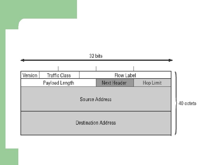
Base Header l l l Version - Specifies the version number - 4 bits Priority - Priority of the packet with respect to traffic congestion - Congestion-controlled (0 -7) - Noncongestion-controlled (8 -15) - 4 bits Traffic Class - Class of service desired for the datagram - 8 bits
l l l Flow Label - Provide special handling for a particular flow of data - 20 bits Payload Length - Length of the data field (excluding the base header) in the datagram - 16 bits Next Header - Defining the header that follows the base header in datagram - 8 bits
l l l Hop Limit - Specifies the maximum number of hops a packet may travel before reaching the destination - 8 bits Source Address - Identifies the original source of the datagram - 128 bits Destination Address - Identifies the final destination of the datagram - 128 bits
IPv 6 EXTENSION HEADER
IPv 6 EXTENSION HEADER
l - Extension headers support extra functionalities. placed between the basic header and the payload. each of them contains its own Next Header Field. (daisy chained ) are placed in order.
DAISY-CHAIN EXTENSION HEADER Basic header Next header= TCP segment Basic header Routing header Fragment Authentication Next header= header Header TCP routing fragment Next header= segment authentication TCP
TYPES OF EXTENSION HEADERS l l l Hop-by-hop options header (header code: 0) Routing header (header code: 43) Fragment header (header code: 44) Authentication header (header code: 51) Encapsulating security payload header (header code: 52) Destination options header (header code: 60)
HOP-BY-HOP OPTIONS HEADER l Implement an efficient method to alert routers of a packet that requires special processing.
ROUTING HEADER l l l used by the source to control the routing of packet. explicitly dictate the route from the source to the destination. contains a list of one or more intermediate nodes to be visited on the way to a packet’s destination.
FRAGMENT HEADER l l - allows fragmented packets to traverse the IPv 6 network. Performing by source nodes, not by routers along a packet’s delivery path. simplifies the routers’ work and makes routing go faster.
will discards the packet that is too big send an ICMP packet back to the source use a path MTU discovery technique to find the smallest MTU supported by any network on the path Source then fragments by using this knowledge
l Otherwise, the source must limit all packets to 1280 octets(the minimum MTU that must be supported by each network).
AUTHENTICATION HEADER l l uses an algorithm to ensure that the IPv 6 packet has not been altered along its path. Ensures that the IPv 6 packet has arrived from the sourced listed in the IP Header. Provides a mechanism by which the receiver of a packet can be sure of who sent it. Use cryptographic techniques to encrypt the contents of a packet so that only the intendend recipient can read it.
ENCAPSULATING SECURITY PAYLOAD HEADER l l For packets that must be sent secretly. Provide confidentiality and privacy.
DESTINATION OPTION HEADER l l optional information to be examined by the destination node. Not use during routing.
IPv 6 ADDRESSING
Brief Introduction l l Provides 128 bit address space allows for 2128 ≈ 1040 different addresses can address 3. 4 x 1038 nodes if address assignment efficiency is 100%. 3 basic types: – – – Unicast Anycast Multicast
Unicast Address l Corresponds to a single computer l The format is: 010 Registry Provider Subscriber Subnet Interface
Unicast Address l 3 types of Unicast Address – – Global unicast n bits m bits 128 – n – m – bits Global Routing Prefix Subnet Id Interface ID Site-local unicast l it is designed to used for addressing inside of a site without the need for a glocal prefix 10 bits 54 bits 64 bits 1111111011 Subnet ID Interface ID
Unicast Address – Link - local unicast l it is used on a single link. The addresses are designed on a single link for purposes such as automatic address configuration, neighbor discovery, or when no routers are present 10 bits 54 bits 64 bits 1111111010 0 Interface ID
Anycast Address l l assigned to more than one interface, with the property that a packet sent to an anycast address is routed to the “nearest” interface having that address, according to the routing protocols’ measurement. allocated from the unicast address space by using any of the defined unicast address formats
Anycast Address l A longest prefix P identifies the topological region in which all interfaces belonging to that anycast address reside. l Within the region identified by P, the anycast address must be maintained as a separate entry in the routing system l Outside the region identified by P, the anycast address may be aggregated into the routing entry for prefix P.
Multicast Address l Pre-defined Multicast addresses – l defined for explicit scope values The following slide shows the reserved Multicast Addresses. This reserved addresses shall never be assigned to any multicast group.
Multicast Address FF 00: 0: 0 FF 01: 0: 0: 0: 0 FF 02: 0: 0: 0: 0 FF 03: 0: 0: 0: 0 FF 04: 0: 0: 0: 0 FF 05: 0: 0: 0: 0 FF 06: 0: 0: 0: 0 FF 07: 0: 0: 0: 0 FF 08: 0: 0: 0: 0 FF 09: 0: 0: 0: 0 FF 0 A: 0: 0: 0: 0 FF 0 B: 0: 0: 0: 0 FF 0 C: 0: 0: 0: 0 FF 0 D: 0: 0: 0: 0 FF 0 E: 0: 0: 0: 0 FF 0 F: 0: 0: 0: 0
Multicast Address l All nodes addresses – identify the group of all IPv 6 nodes within 1 scope 1 (interface-local) or 2 (link-local). FF 01: 0: 0: 0: 1 FF 02: 0: 0: 0: 1
Multicast Address l All routers addresses – identify the group of all IPv 6 routers within scope 1 (interface-local), 2 (link-local), or 5 (site-local). FF 01: 0: 0: 0: 2 FF 02: 0: 0: 0: 2 FF 05: 0: 0: 0: 2
Multicast Address l Solicited-Nodes Address: – – – Computed as a function of a node’s unicast and anycast addresses formed by taking the low-order 24 bits of an address (unicast or anycast) and appending those bits to the prefix FF 02: 0: 0: 1: FF 00: : /104 resulting in a multicast address in the range FF 02: 0: 0: 1: FF 00: 0000 to FF 02: 0: 0: 1: FFFF. Format: FF 02: 0: 0: 1: FFXX: XXXX
Address Notation l Normally, a 128 -bit number written in dotted decimal notation: 105. 220. 136. 100. 255. 0. 0. 18. 128. 140. 10. 255
Address Notation l Colon Hexadecimal Notation – – Reduced the number of characters used to write an address each group of 16 bits is written in hexadecimal with a colon separating groups 105. 220. 136. 100. 255. 0. 0. 18. 128. 140. 10. 255. 25 69 DC: 8864: FFFF: 0: 1280: 8 C 0 A: FFFF
Address Notation l Zero Compression – – – replaces sequences of zeros with double semicolons can only once per address Example: FDEC: 0: 0: BBFF: 0: FFFF can be written as FDEC: : BBFF: 0: FFFF
Address Notation l l If the 0 string begins the address, the notation starts with the double colon. Example: 0000: 0 AFF: 1 BDF: 000 F: 0077 can be written as : : 0 AFF: 1 BDF: F: 0077
Address Notation l CIDR Notation. – The example below show can we define a prefix of 60 bits using CIDR. FDEC: 0: 0: BBFF: 0: FFFF/60
IPv 6 CONCLUSION
CONCLUSION l l l IPv 6 come at the right time- Internet growing so rapidly. Solution of the new disruptive applications. IPv 4 IPv 6 -larger task for some company or industry, but the rate of IPv 4 address consumption is rapidly increasing.
l IPv 6 has a bright future. – – – allow us to build a more robust and reliable Internet. simplify the implementation and deployment of emergency response networks. making our lives safer & more secure.