
IP Qo S Principles Theory and Practice Dimitrios
- Slides: 108
IP Qo. S Principles Theory and Practice Dimitrios Kalogeras
A Bit of History l The Internet, originally designed for U. S. government use, offered only one service level: Best Effort. – – l No guarantees of transit time or delivery Rudimentary prioritization was available, but it was rarely used. Commercialization began in early 1990’s – – – Private (intranet) networks using Internet technology appeared. Commercial users began paying directly for Internet use. Commerce sites tried to attract customers by using graphics. Industry used the Internet and intranets for internal, shared communications that combined previously-separate, specialized networks -- each with its own specific technical requirements. New technologies (voice over the Internet, etc. ) appeared, designed to capitalize on inexpensive Internet technologies.
The Demands on Modern Networks l Network flexibility is becoming central to enterprise strategy – – l l l Rapidly-changing business functions no longer carried out in stable ways, in unchanging locations, or for long time-periods Network-enabled applications often crucial for meeting new market opportunities, but there’s no time to custom-build a network Traffic is bursty Interactive voice, video applications have stringent bandwidth and latency demands Multiple application networks are being combined into consolidated corporate utility networks – – Bandwidth contention as critical transaction traffic is squeezed by web browsing, file transfers, or other low-priority or bulk traffic Latency problems as interactive voice and video are squeezed by transaction, web browsing, file transfer, and bulk traffic
Definitions l Quality of Service (Qo. S) classifies network traffic and then ensures that some of it receives special handling. – – l Differentiated Class of Service (Co. S) is a simpler alternative to Qo. S. – – l May track each individual dataflow (sender: receiver) separately. May include attempts to provide better error rates, lower network transit time (latency), and decreased latency variation (jitter). Doesn't try to distinguish among individual dataflows; instead, uses simpler methods to classify packets into one of a few categories. All packets within a particular category are then handled in the same way, with the same quality parameters. Policy-Based Networking provides end-to-end control. – The rules for access and for management of network resources are stored as policies and are managed by a policy server.
Qo. S Background Qo. S development inspired by new types of applications in IP environment: l l 5 Video Streaming Services Video Conferencing Vo. IP Legacy SNA / DLSw
Qo. S Architecture Models l l l 6 Best Effort Service Integrated Service Differentiated Service
Best Effort Service What exactly IP does: l l l 7 All packets treated equally Unpredictable bandwidth Unpredictable delay and jitter
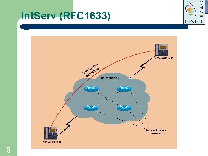
Int. Serv (RFC 1633) 8
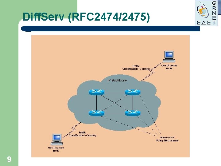
Diff. Serv (RFC 2474/2475) 9
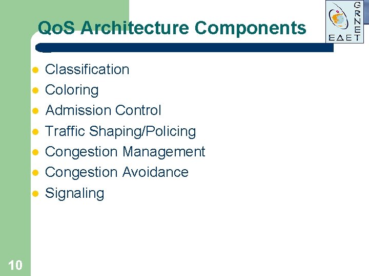
Qo. S Architecture Components l l l l 10 Classification Coloring Admission Control Traffic Shaping/Policing Congestion Management Congestion Avoidance Signaling
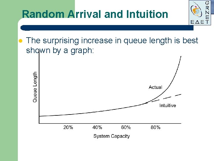
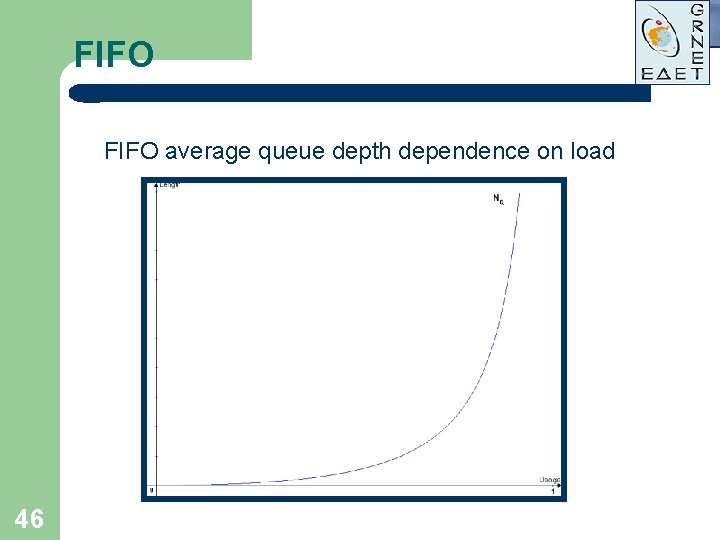
Statistical Behavior: Random Arrival l In random arrival, the time that each packet arrives is completely independent of the time that any other packet arrives. – – l If the true situation is that arrivals tend to be evenly spaced, then random arrival calculations will overestimate the queuing delay. If the true situation is that arrivals are bunched in groups (typical of data flows, such as packets and acknowledgements), then random arrival calculations will underestimate the queuing delay. Our intuition is usually misleading when we think of random processes. – – We tend to assume that queue size increases linearly as the number of customers increases. But, with random arrival, there is a drastic increase in queue size as the customer arrival rate approaches 80% of theoretical server capacity. There’s no way to store the capacity that is unused by late customers, but early customers increase the queue.
Random Arrival and Intuition l The surprising increase in queue length is best shown by a graph:
Random Arrival vs. Self-Similar l Although random arrival is very convenient mathematically (it’s relatively simple to do random arrival calculations), it has been shown that much data traffic is self-similar. – – l Self-similar traffic shows the same pattern regardless of changes in scale. – l Ethernet and Internet traffic flows, in particular, are self-similar. The rate of initial connections is still random, however. Fractal geometry (e. g. , a coastline) is an example. Self-similar traffic has a heavy tail. – – The probabilities of extremely large values (e. g. , file lengths of a gigabyte or more) don’t decrease as rapidly, as they would with random distributions of file lengths. This matches real data traffic behaviors. l l Long file downloads mixed with short acknowledgements Compressed video with action scenes mixed with static scenes
Traffic Classification l l l 14 Most fundamental Qo. S building block The component of a Qo. S feature that recognizes and distinguishes between different traffic streams Without classification, all packets are treated the same
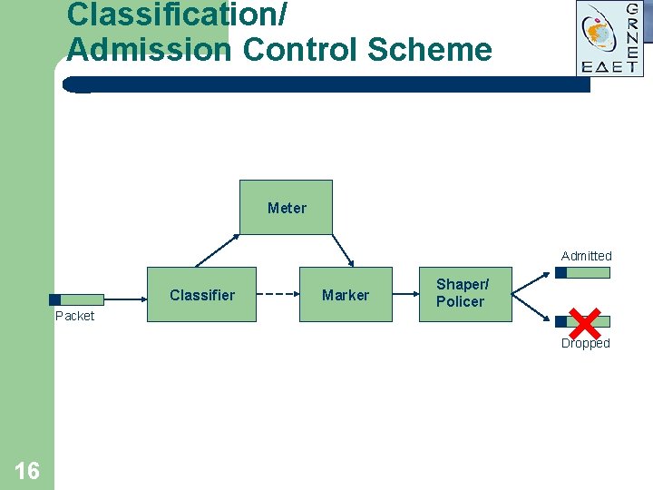
Traffic Classification/ Admission Control Issues l l 15 Always performed at the network perimeter Makes traffic conform to the internal network policy Marks packets with special flags (colors) Colors used afterwards inside the network for Qo. S management
Classification/ Admission Control Scheme Meter Admitted Classifier Packet Marker Shaper/ Policer Dropped 16
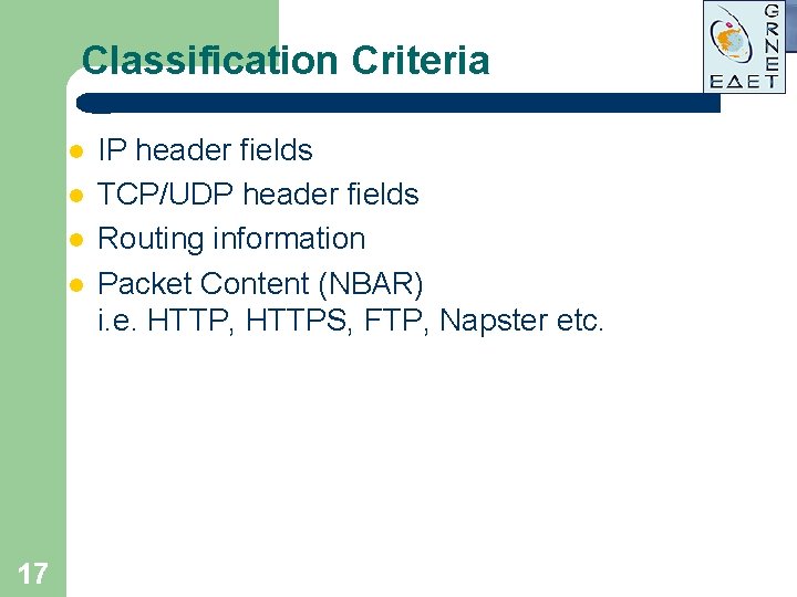
Classification Criteria l l 17 IP header fields TCP/UDP header fields Routing information Packet Content (NBAR) i. e. HTTP, HTTPS, FTP, Napster etc.
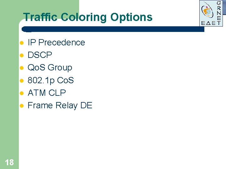
Traffic Coloring Options l l l 18 IP Precedence DSCP Qo. S Group 802. 1 p Co. S ATM CLP Frame Relay DE
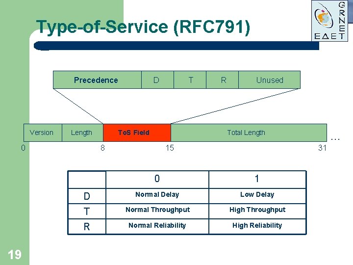
Type-of-Service (RFC 791) Precedence Version Length 0 19 D T To. S Field R Unused Total Length 8 15 … 31 0 1 D Normal Delay Low Delay T Normal Throughput High Throughput R Normal Reliability High Reliability
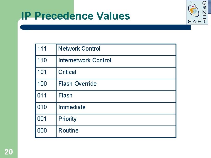
IP Precedence Values 20 111 Network Control 110 Internetwork Control 101 Critical 100 Flash Override 011 Flash 010 Immediate 001 Priority 000 Routine
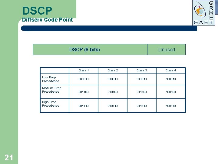
DSCP Diffserv Code Point DSCP (6 bits) Class 1 Class 2 Class 3 Class 4 001010 010010 011010 100010 Medium Drop Precedence 001100 010100 011100 100100 High Drop Precedence 001110 010110 011110 100110 Low Drop Precedence 21 Unused
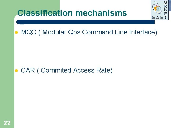
Classification mechanisms 22 l MQC ( Modular Qos Command Line Interface) l CAR ( Commited Access Rate)
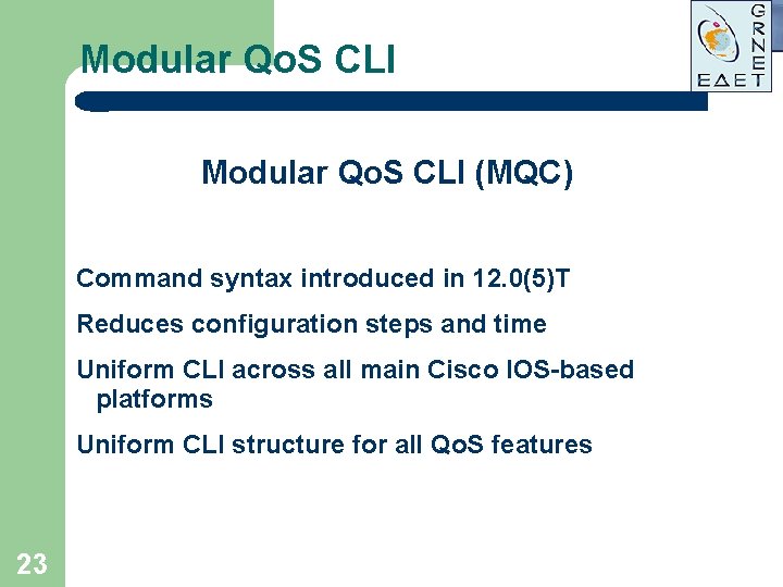
Modular Qo. S CLI (MQC) Command syntax introduced in 12. 0(5)T Reduces configuration steps and time Uniform CLI across all main Cisco IOS-based platforms Uniform CLI structure for all Qo. S features 23
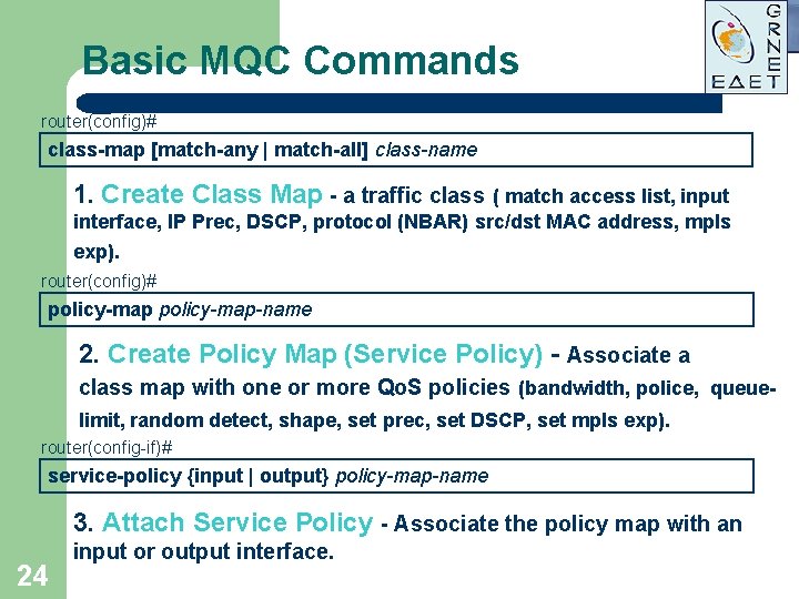
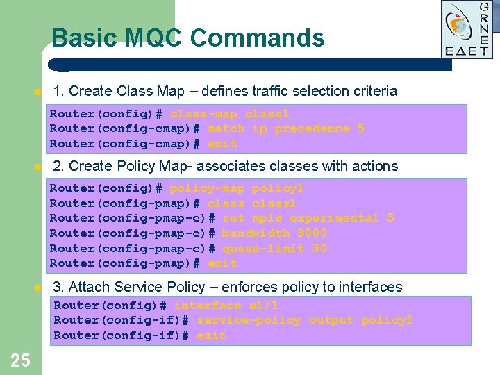
Basic MQC Commands router(config)# class-map [match-any | match-all] class-name • 1. Create Class Map - a traffic class ( match access list, input interface, IP Prec, DSCP, protocol (NBAR) src/dst MAC address, mpls exp). router(config)# policy-map-name • 2. Create Policy Map (Service Policy) - Associate a class map with one or more Qo. S policies (bandwidth, police, queuelimit, random detect, shape, set prec, set DSCP, set mpls exp). router(config-if)# service-policy {input | output} policy-map-name • 3. Attach Service Policy - Associate the policy map with an 24 input or output interface.
Basic MQC Commands l 1. Create Class Map – defines traffic selection criteria Router(config)# class-map class 1 Router(config-cmap)# match ip precedence 5 Router(config-cmap)# exit l 2. Create Policy Map- associates classes with actions Router(config)# policy-map policy 1 Router(config-pmap)# class 1 Router(config-pmap-c)# set mpls experimental 5 Router(config-pmap-c)# bandwidth 3000 Router(config-pmap-c)# queue-limit 30 Router(config-pmap)# exit l 3. Attach Service Policy – enforces policy to interfaces Router(config)# interface e 1/1 Router(config-if)# service-policy output policy 1 Router(config-if)# exit 25
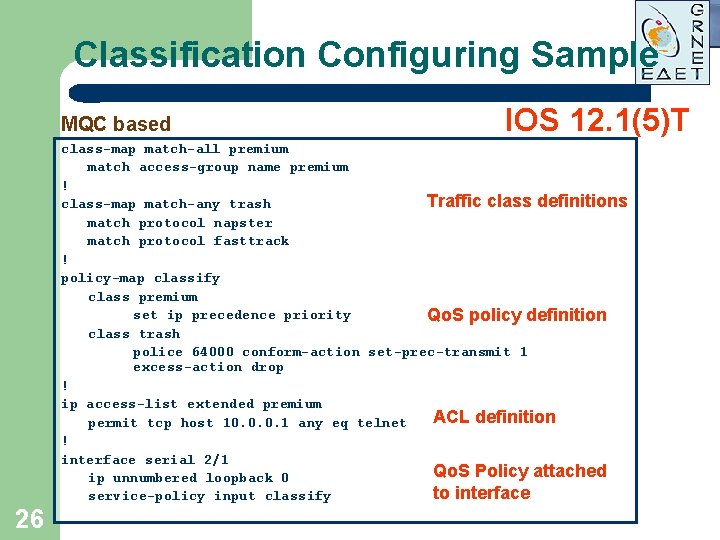
Classification Configuring Sample MQC based IOS 12. 1(5)T class-map match-all premium match access-group name premium ! Traffic class definitions class-map match-any trash match protocol napster match protocol fasttrack ! policy-map classify class premium set ip precedence priority Qo. S policy definition class trash police 64000 conform-action set-prec-transmit 1 excess-action drop ! ip access-list extended premium ACL definition permit tcp host 10. 0. 0. 1 any eq telnet ! interface serial 2/1 Qo. S Policy attached ip unnumbered loopback 0 to interface service-policy input classify 26
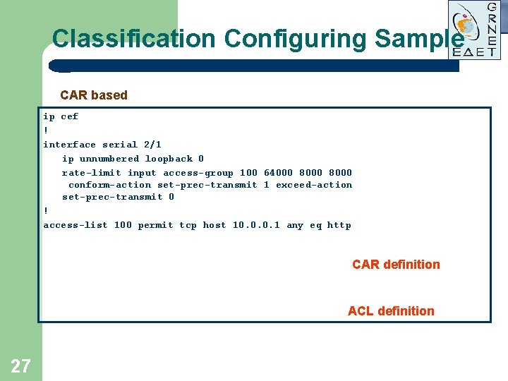
Classification Configuring Sample CAR based ip cef ! interface serial 2/1 ip unnumbered loopback 0 rate-limit input access-group 100 64000 8000 conform-action set-prec-transmit 1 exceed-action set-prec-transmit 0 ! access-list 100 permit tcp host 10. 0. 0. 1 any eq http CAR definition ACL definition 27
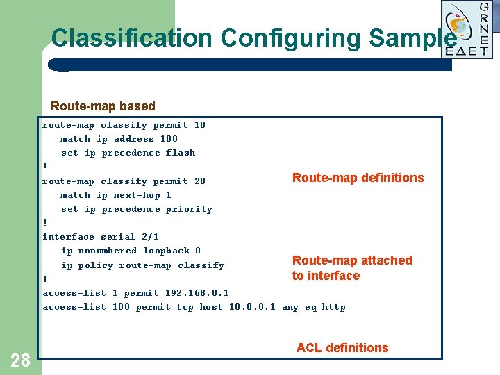
Classification Configuring Sample Route-map based route-map classify permit 10 match ip address 100 set ip precedence flash ! Route-map definitions route-map classify permit 20 match ip next-hop 1 set ip precedence priority ! interface serial 2/1 ip unnumbered loopback 0 Route-map attached ip policy route-map classify to interface ! access-list 1 permit 192. 168. 0. 1 access-list 100 permit tcp host 10. 0. 0. 1 any eq http 28 ACL definitions
Shaping/Policing l l 29 Used to assign more predictive behavior to traffic Uses Token Bucket model
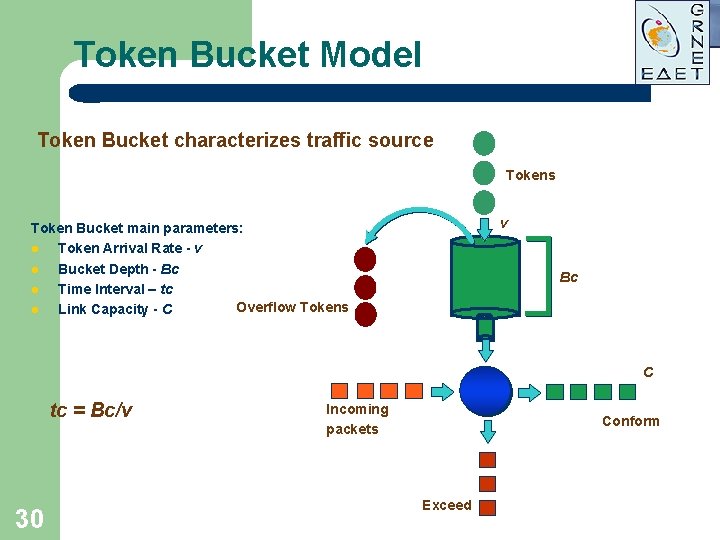
Token Bucket Model Token Bucket characterizes traffic source Tokens v Token Bucket main parameters: l Token Arrival Rate - v l Bucket Depth - Bc l Time Interval – tc Overflow Tokens l Link Capacity - C Bc C tc = Bc/v 30 Incoming packets Conform Exceed
Token Bucket Model l l l 31 Bucket is being filled with tokens at a rate v token/sec. When bucket is full all the excess tokens are discarded. When packet of size L arrives, bucket is checked for availability of corresponding amount of tokens. If several packets arrive back-to-back and there are sufficient tokens to serve them all, they are accepted at peak rate (usually physical link speed). If enough tokens available, packet is optionally colored and accepted to the network and corresponding amount of tokens is subtracted from the bucket. If not enough tokens, special action on packet is performed.
Token Bucket Model Actions performed on nonconforming packets: l Dropped (Policing) l Delayed in queue either FIFO or WFQ (Shaping) l Colored/Recolored 32
Token Bucket Model Bucket depth variation effect: l Bc = 0 Constant Bit Rate (CBR) l Bc No Regulation Bucket depth is characteristic of traffic burstiness Maximum number of bytes transmitted over period of time t: A( t)max = Bc+v· t 33
Excess Burst (Be) Cisco Implementation GTS ( Generic Traffic Shaping) If during previous tcn-1 interval bucket Bc was not depleted (there is no congestion), in the next interval tcn Bc+Be bytes are available for burst. In frame relay implementations packets admitted via Be tokens are marked with DE bit. 34
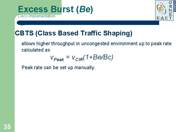
Excess Burst (Be) Cisco Implementation CBTS (Class Based Traffic Shaping) allows higher throughput in uncongested environment up to peak rate calculated as v. Peak = v. CIR(1+Be/Bc) Peak rate can be set up manually. 35
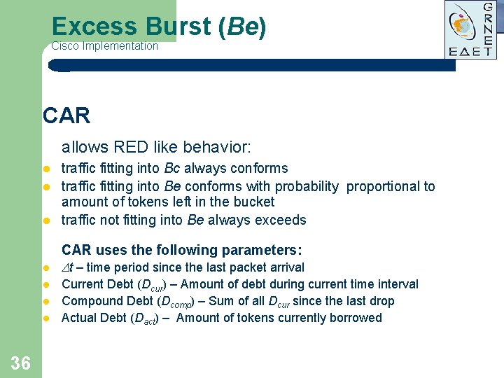
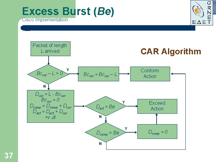
Excess Burst (Be) Cisco Implementation CAR allows RED like behavior: l traffic fitting into Bc always conforms traffic fitting into Be conforms with probability proportional to amount of tokens left in the bucket traffic not fitting into Be always exceeds l CAR uses the following parameters: t – time period since the last packet arrival l l 36 Current Debt (Dcur) – Amount of debt during current time interval Compound Debt (Dcomp) – Sum of all Dcur since the last drop Actual Debt (Dact) – Amount of tokens currently borrowed
Excess Burst (Be) Cisco Implementation Packet of length L arrived Bccur – L > 0 Y CAR Algorithm Conform Action Bccur = Bccur – L N Dcur = L - Bccur = 0 Dcomp = Dcomp + Dcur Dact = Dact + Dcur +v· t Dact > Be Exceed Action N Dcomp > Be N 37 Y Y Dcomp = 0
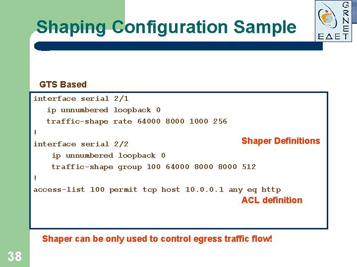
Shaping Configuration Sample GTS Based interface serial 2/1 ip unnumbered loopback 0 traffic-shape rate 64000 8000 1000 256 ! Shaper Definitions interface serial 2/2 ip unnumbered loopback 0 traffic-shape group 100 64000 8000 512 ! access-list 100 permit tcp host 10. 0. 0. 1 any eq http ACL definition Shaper can be only used to control egress traffic flow! 38
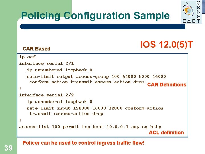
Policing Configuration Sample CAR Based IOS 12. 0(5)T ip cef interface serial 2/1 ip unnumbered loopback 0 rate-limit output access-group 100 64000 8000 16000 conform-action transmit excess-action drop CAR Definitions ! interface serial 2/2 ip unnumbered loopback 0 rate-limit input 128000 16000 32000 conform-action transmit excess-action drop ! access-list 100 permit tcp host 10. 0. 0. 1 any eq http ACL definition 39 Policer can be used to control ingress traffic flow!
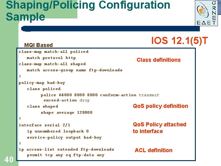
Shaping/Policing Configuration Sample MQI Based 40 IOS 12. 1(5)T class-map match-all policed match protocol http Class definitions class-map match-all shaped match access-group name ftp-downloads ! policy-map bad-boy class policed police 64000 8000 conform-action transmit exceed-action drop class shaped Qo. S policy definition shape average 128000 ! interface serial 2/1 Qo. S Policy attached ip unnumbered loopback 0 to interface service-policy output bad-boy ! ip access-list extended ftp-downloads ACL definition permit tcp any eq ftp-data any
CAR Policing Problem Why cannot my traffic reach CIR value? Cause: Improper setting of Bc and Be values CAR is aggressive, as drops excessive packets and the lost data needs to be retransmitted by upper layers (mainly TCP) after timeout. This also causes TCP to shrink its window reducing flow throughput. Cisco Systems recommends the following settings: Bc = 1. 5 x. CIR/8 Be = 2 x. Bc 41
Congestion Management 42
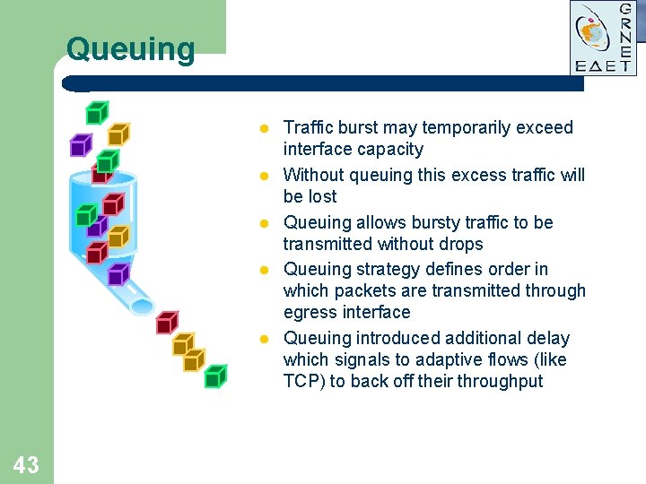
Queuing l l l 43 Traffic burst may temporarily exceed interface capacity Without queuing this excess traffic will be lost Queuing allows bursty traffic to be transmitted without drops Queuing strategy defines order in which packets are transmitted through egress interface Queuing introduced additional delay which signals to adaptive flows (like TCP) to back off their throughput
Queuing Algorithms l l 44 FIFO Priority (Absolute) Weighted Round Robin (WRR) Fair
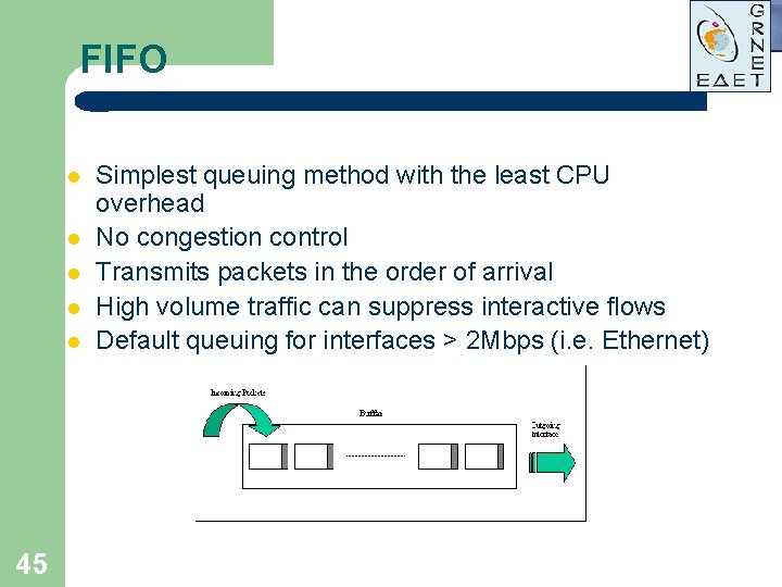
FIFO l l l 45 Simplest queuing method with the least CPU overhead No congestion control Transmits packets in the order of arrival High volume traffic can suppress interactive flows Default queuing for interfaces > 2 Mbps (i. e. Ethernet)
FIFO average queue depth dependence on load 46
Absolute Priority Queuing l l 47 Generic Priority Queuing Custom Queuing RTP Priority Queuing Low Latency Queuing (LLQ)
Simplest Qo. S Algorithm: Priority Queuing l Stated requirement: –“If <application> has traffic waiting, send it next” next l Commonly –Defined 48 implemented behavior of IP precedence
Priority Queuing Implementation Approach l Identify interesting traffic –Access l Place lists traffic in various queues l Dequeue in order of queue precedence 49
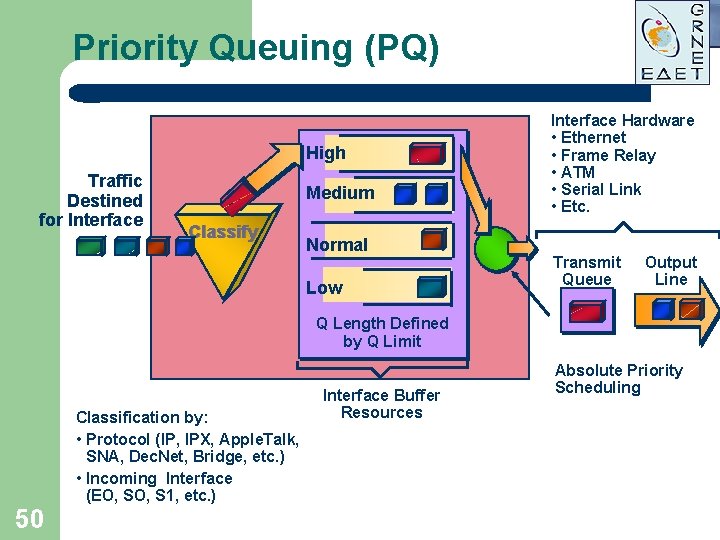
Priority Queuing (PQ) High Traffic Destined for Interface Medium Classify Normal Low Interface Hardware • Ethernet • Frame Relay • ATM • Serial Link • Etc. Transmit Queue Output Line Q Length Defined by Q Limit Classification by: • Protocol (IP, IPX, Apple. Talk, SNA, Dec. Net, Bridge, etc. ) • Incoming Interface (EO, S 1, etc. ) 50 Interface Buffer Resources Absolute Priority Scheduling
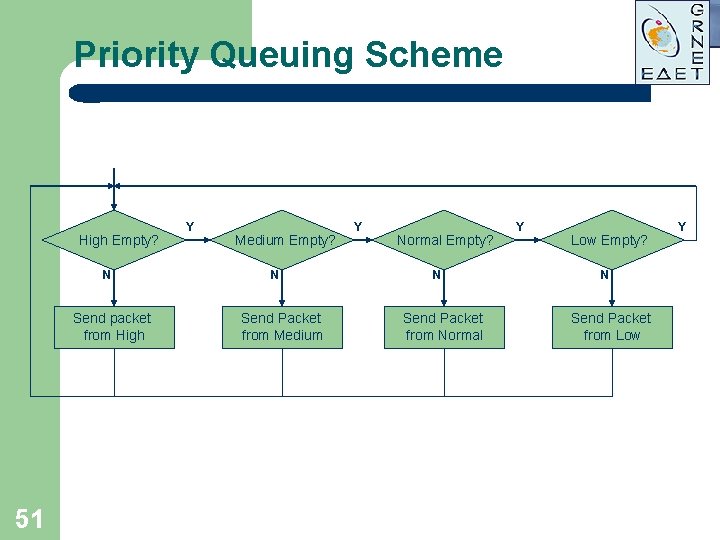
Priority Queuing Scheme High Empty? N Send packet from High 51 Y Medium Empty? N Send Packet from Medium Y Normal Empty? N Send Packet from Normal Y Low Empty? N Send Packet from Low Y
Generic PQ Drawbacks l l l 52 Needs thorough admission control No upper limit for each priority level High risk of low priority queues` starvation effect
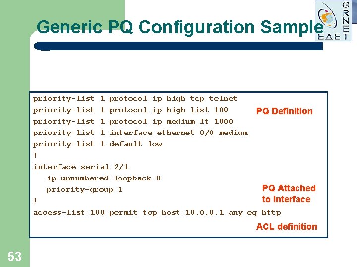
Generic PQ Configuration Sample priority-list 1 protocol ip high tcp telnet priority-list 1 protocol ip high list 100 PQ Definition priority-list 1 protocol ip medium lt 1000 priority-list 1 interface ethernet 0/0 medium priority-list 1 default low ! interface serial 2/1 ip unnumbered loopback 0 PQ Attached priority-group 1 to Interface ! access-list 100 permit tcp host 10. 0. 0. 1 any eq http ACL definition 53
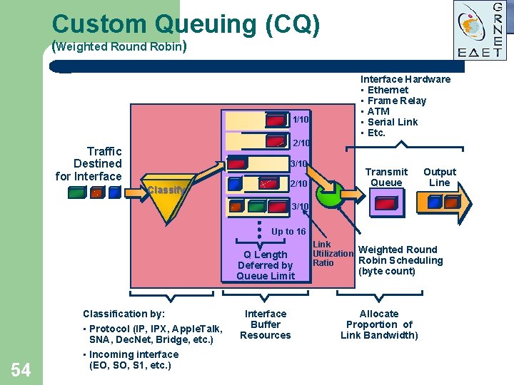
Custom Queuing (CQ) (Weighted Round Robin) 1/10 Interface Hardware • Ethernet • Frame Relay • ATM • Serial Link • Etc. 2/10 Traffic Destined for Interface 3/10 Classify 2/10 Transmit Queue Output Line 3/10 Up to 16 Q Length Deferred by Queue Limit Classification by: 54 • Protocol (IP, IPX, Apple. Talk, SNA, Dec. Net, Bridge, etc. ) • Incoming interface (EO, S 1, etc. ) Interface Buffer Resources Link Utilization Weighted Round Robin Scheduling Ratio (byte count) Allocate Proportion of Link Bandwidth)
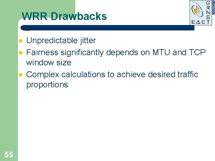
WRR Drawbacks l l l 55 Unpredictable jitter Fairness significantly depends on MTU and TCP window size Complex calculations to achieve desired traffic proportions
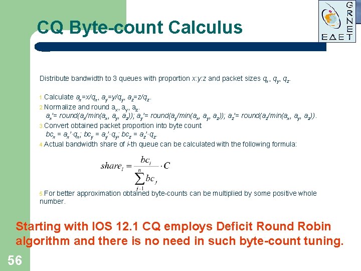
CQ Byte-count Calculus Distribute bandwidth to 3 queues with proportion x: y: z and packet sizes qx, qy, qz. 1. Calculate ax=x/qx, ay=y/qy, az=z/qz. 2. Normalize and round ax, ay, az. ax’= round(ax/min(ax, ay, az)); ay’= round(ay/min(ax, ay, az)); az’= round(az/min(ax, ay, az)). 3. Convert obtained packet proportion into byte count bcx = ax’·qx; bcy = ay’·qy; bcz = az’·qz. 4. Actual bandwidth share of i-th queue can be calculated with the following formula: 5. For better approximation obtained byte-counts can be multiplied by some positive whole number. Starting with IOS 12. 1 CQ employs Deficit Round Robin algorithm and there is no need in such byte-count tuning. 56
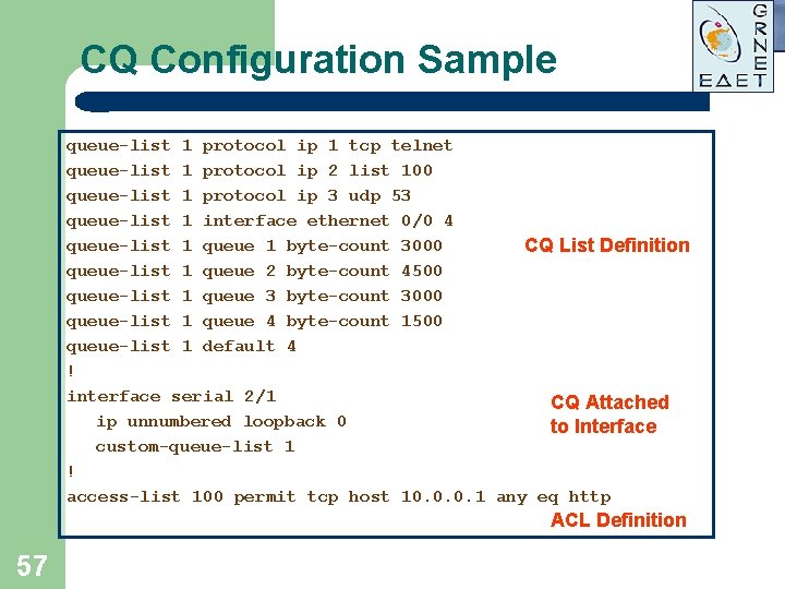
CQ Configuration Sample queue-list 1 protocol ip 1 tcp telnet queue-list 1 protocol ip 2 list 100 queue-list 1 protocol ip 3 udp 53 queue-list 1 interface ethernet 0/0 4 queue-list 1 queue 1 byte-count 3000 CQ List Definition queue-list 1 queue 2 byte-count 4500 queue-list 1 queue 3 byte-count 3000 queue-list 1 queue 4 byte-count 1500 queue-list 1 default 4 ! interface serial 2/1 CQ Attached ip unnumbered loopback 0 to Interface custom-queue-list 1 ! access-list 100 permit tcp host 10. 0. 0. 1 any eq http ACL Definition 57
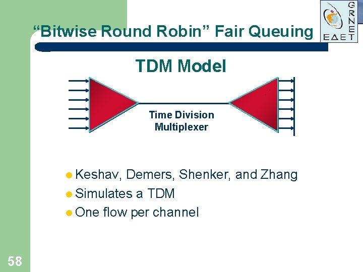
“Bitwise Round Robin” Fair Queuing TDM Model Time Division Multiplexer l Keshav, Demers, Shenker, and Zhang l Simulates a TDM l One flow per channel 58
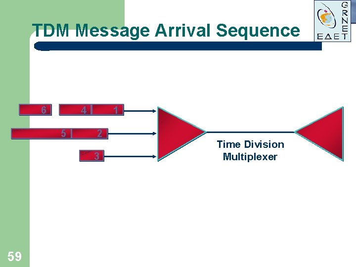
TDM Message Arrival Sequence 6 4 5 1 2 3 59 Time Division Multiplexer
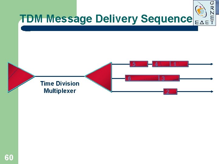
TDM Message Delivery Sequence 5 Time Division Multiplexer 60 6 4 1 3 2
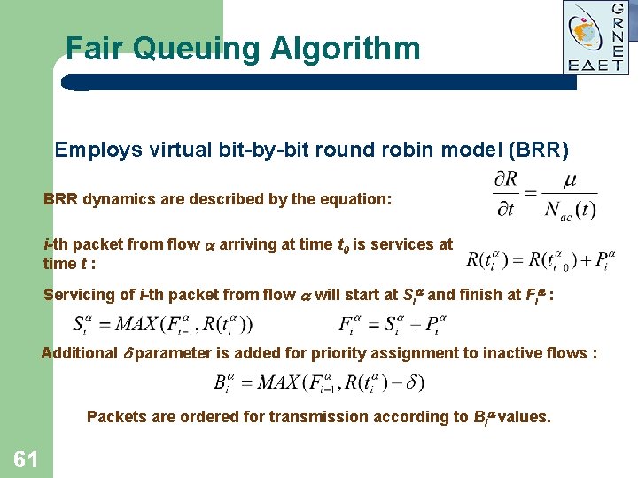
Fair Queuing Algorithm Employs virtual bit-by-bit round robin model (BRR) BRR dynamics are described by the equation: i-th packet from flow a arriving at time t 0 is services at time t : Servicing of i-th packet from flow a will start at Sia and finish at Fia : Additional parameter is added for priority assignment to inactive flows : Packets are ordered for transmission according to Bia values. 61
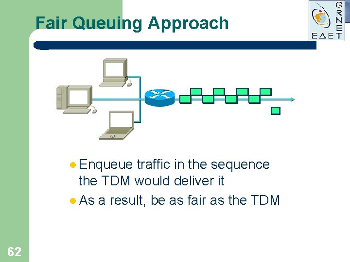
Fair Queuing Approach l Enqueue traffic in the sequence the TDM would deliver it l As a result, be as fair as the TDM 62
Effects of Fair Queuing l Low-bandwidth flows get –As much bandwidth as they can use –Timely service l High-bandwidth –Interleave flows traffic –Cooperatively share bandwidth –Absorb latency 63
What Weighting Does l In TDM –Channel l In speed determines message “duration” WFQ –Multiplier on message length changes simulated message “duration” l Result: –Flow’s 64 “fair” share predictably unfair
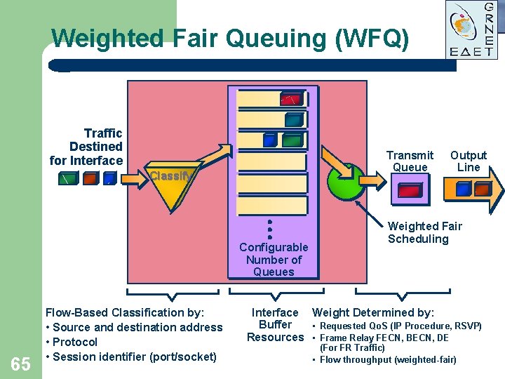
Weighted Fair Queuing (WFQ) Traffic Destined for Interface Transmit Queue Classify Configurable Number of Queues 65 Flow-Based Classification by: • Source and destination address • Protocol • Session identifier (port/socket) Output Line Weighted Fair Scheduling Interface Weight Determined by: Buffer • Requested Qo. S (IP Procedure, RSVP) Resources • Frame Relay FECN, BECN, DE (For FR Traffic) • Flow throughput (weighted-fair)
Weighted Fair Queuing (WFQ) l l l 66 Fair bandwidth per flow allocation Low delay for interactive applications Protection from ill-behaved sources
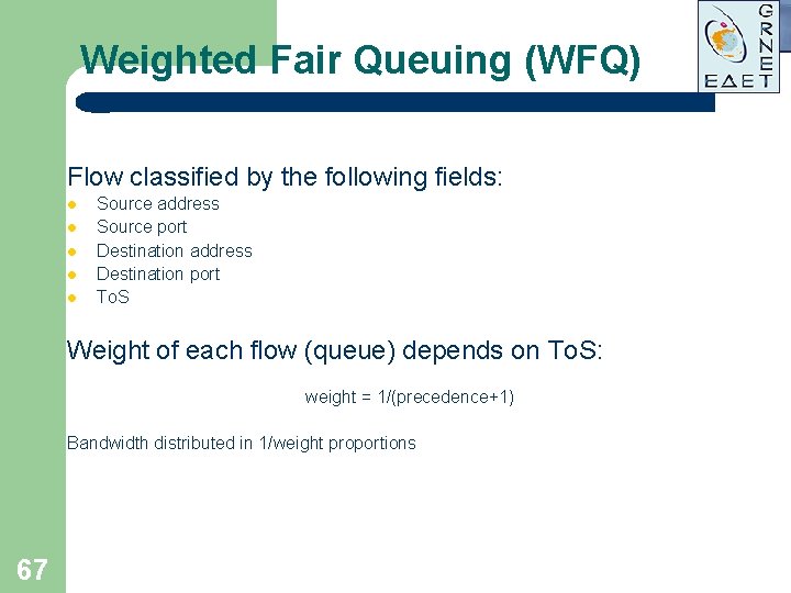
Weighted Fair Queuing (WFQ) Flow classified by the following fields: l l l Source address Source port Destination address Destination port To. S Weight of each flow (queue) depends on To. S: weight = 1/(precedence+1) Bandwidth distributed in 1/weight proportions 67
Weighted Fair Queuing (WFQ) l l 68 Packets are ordered according to the expected virtual departure time of their last bit. Low volume flows have preference over high volume transfers. Low volume flow is identified as using less than its share of bandwidth. The special queue length threshold value is established, after which only low volume flows can enqueue. All the packets, that belong to high volume flows are dropped.
Drawbacks of Weighted Fair Queuing l Requires more sorting than other approaches 69
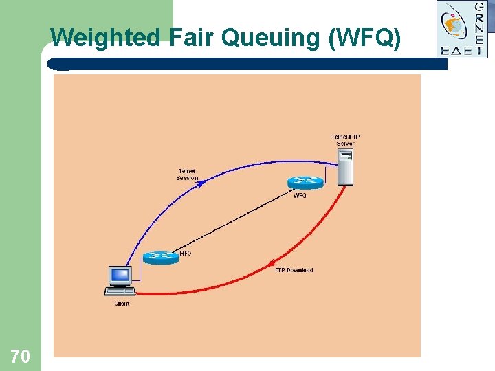
Weighted Fair Queuing (WFQ) Delay FTP Telnet t 70
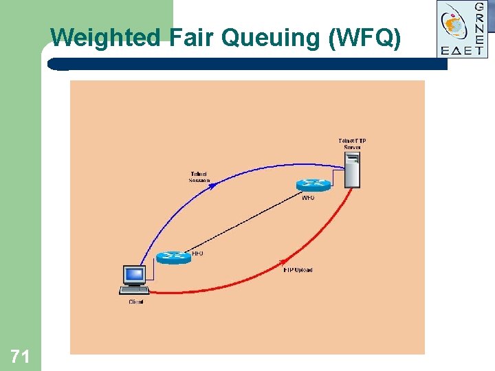
Weighted Fair Queuing (WFQ) FTP Delay Telnet t 71
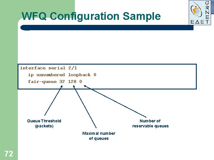
WFQ Configuration Sample interface serial 2/1 ip unnumbered loopback 0 fair-queue 32 128 0 Queue Threshold (packets) Number of reservable queues Maximal number of queues 72
RTP Priority Queuing l l l 73 Classifies only by UDP port range Only even ports from the range are classified Establishes upper limit via integrated policer Excess traffic dropped during congestion periods RTP PQ has priority over LLQ
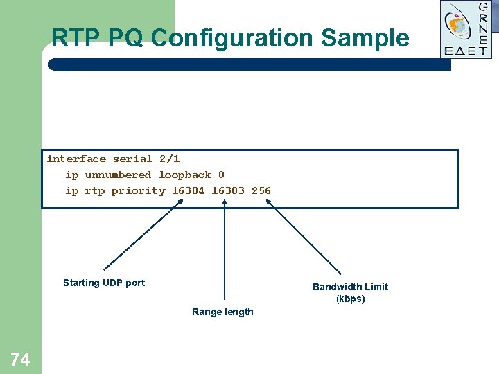
RTP PQ Configuration Sample interface serial 2/1 ip unnumbered loopback 0 ip rtp priority 16384 16383 256 Starting UDP port Bandwidth Limit (kbps) Range length 74
Low Latency Queuing (LLQ) l l 75 Implemented using MQI Very rich classification criteria (class-map) Establishes upper limit via integrated policer Excess traffic dropped during congestion periods
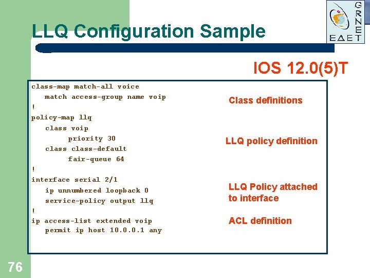
LLQ Configuration Sample IOS 12. 0(5)T class-map match-all voice match access-group name voip ! policy-map llq class voip priority 30 class-default fair-queue 64 ! interface serial 2/1 ip unnumbered loopback 0 service-policy output llq ! ip access-list extended voip permit ip host 10. 0. 0. 1 any 76 Class definitions LLQ policy definition LLQ Policy attached to interface ACL definition
Class Based WFQ (CBWFQ) l l 77 Based on the same algorithm as WFQ Weights can be manually configured Allows to easily specify guaranteed bandwidth for a class Configuration based on Cisco MQI
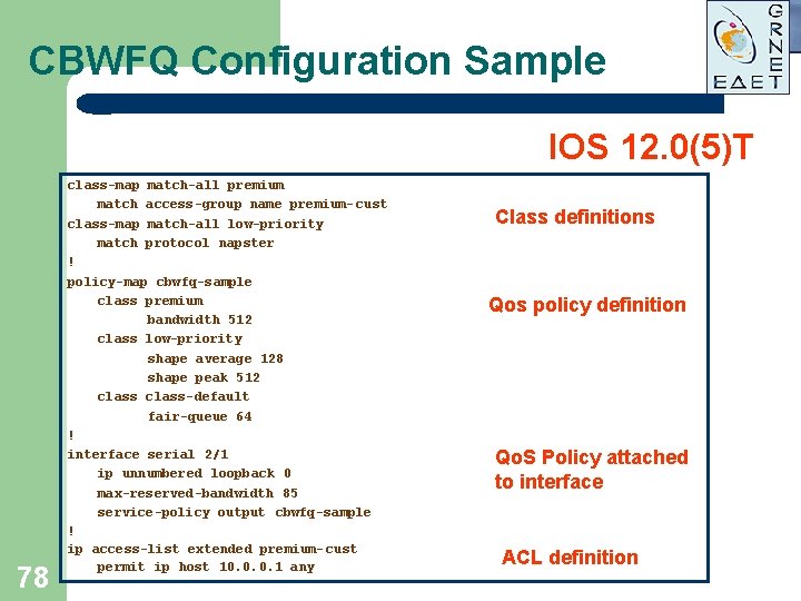
CBWFQ Configuration Sample IOS 12. 0(5)T 78 class-map match-all premium match access-group name premium- cust class-map match-all low-priority match protocol napster ! policy-map cbwfq-sample class premium bandwidth 512 class low-priority shape average 128 shape peak 512 class-default fair-queue 64 ! interface serial 2/1 ip unnumbered loopback 0 max-reserved-bandwidth 85 service-policy output cbwfq-sample ! ip access-list extended premium- cust permit ip host 10. 0. 0. 1 any Class definitions Qos policy definition Qo. S Policy attached to interface ACL definition
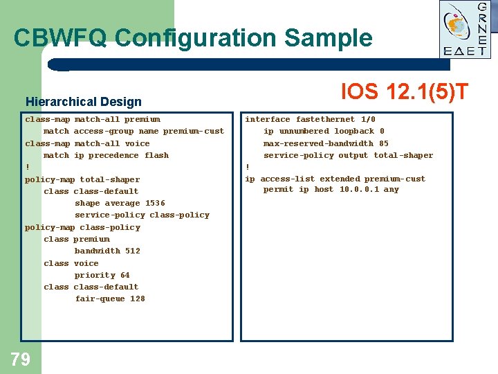
CBWFQ Configuration Sample Hierarchical Design class-map match-all premium match access-group name premium- cust class-map match-all voice match ip precedence flash ! policy-map total-shaper class-default shape average 1536 service-policy class-policy-map class-policy class premium bandwidth 512 class voice priority 64 class-default fair-queue 128 79 IOS 12. 1(5)T interface fastethernet 1/0 ip unnumbered loopback 0 max-reserved-bandwidth 85 service-policy output total-shaper ! ip access-list extended premium- cust permit ip host 10. 0. 0. 1 any
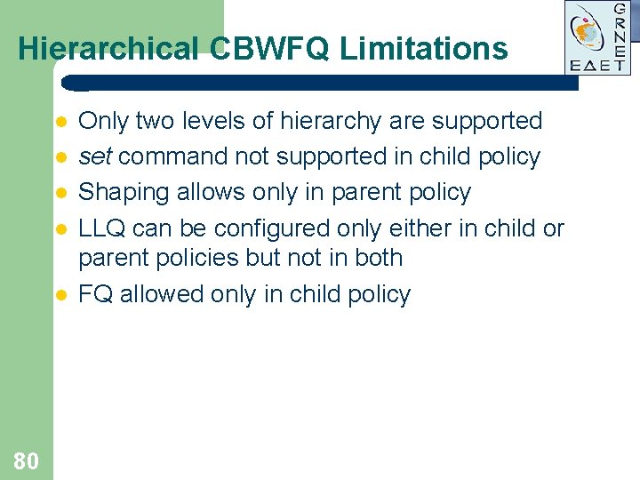
Hierarchical CBWFQ Limitations l l l 80 Only two levels of hierarchy are supported set command not supported in child policy Shaping allows only in parent policy LLQ can be configured only either in child or parent policies but not in both FQ allowed only in child policy
Congestion Avoidance 81
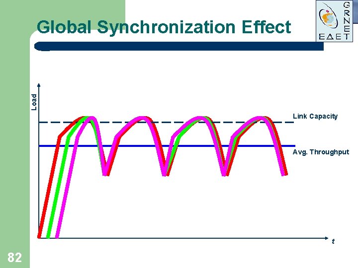
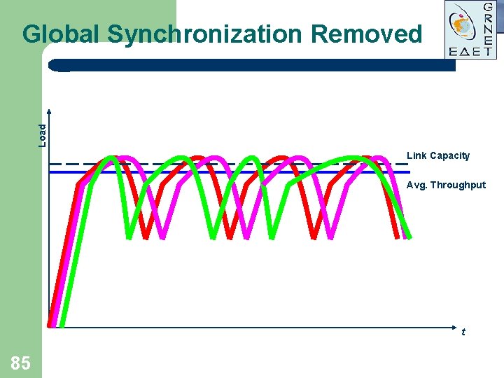
Load Global Synchronization Effect Link Capacity Avg. Throughput t 82
Tail Drop and TCP Flow Control l Packet drops from all TCP sessions simultaneously High probability of multiple drops from the same TCP session Uniformly distributed drops from high volume and interactive flows Result: Low average throughput! 83
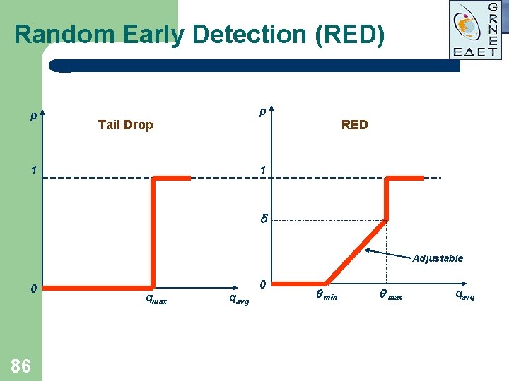
Random Early Detection (RED) Developed by Van Jacobson in 1993 l l l 84 Starts randomly dropping packets before actual congestion occurs Keeps average queue depth low Increases average throughput
Load Global Synchronization Removed Link Capacity Avg. Throughput t 85
Random Early Detection (RED) p p Tail Drop RED 1 1 Adjustable 0 86 0 qmax qavg min max qavg
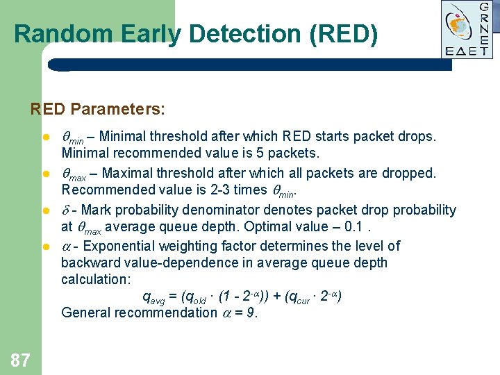
Random Early Detection (RED) RED Parameters: l l 87 min – Minimal threshold after which RED starts packet drops. Minimal recommended value is 5 packets. max – Maximal threshold after which all packets are dropped. Recommended value is 2 -3 times min. - Mark probability denominator denotes packet drop probability at max average queue depth. Optimal value – 0. 1. - Exponential weighting factor determines the level of backward value-dependence in average queue depth calculation: qavg = (qold · (1 - 2 - )) + (qcur · 2 - ) General recommendation = 9.
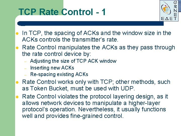
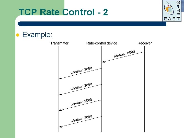
TCP Rate Control - 1 l l In TCP, the spacing of ACKs and the window size in the ACKs controls the transmitter’s rate. Rate Control manipulates the ACKs as they pass through the rate control device by: – – – l l Adjusting the size of TCP ACK window Inserting new ACKs Re-spacing existing ACKs Rate Control works only with TCP; other methods, such as Token Bucket, must be used with UDP. Rate Control violates the protocol layering design, as it allows network devices to manipulate a higher-layer protocol’s operation. Nevertheless, it usually functions well and provides fine-grained control.
TCP Rate Control - 2 l Example:
Weighted Random Early Detection (WRED) l l 90 Modified version of RED Weights determine the set of parameters: min , max and . Weight depends on To. S field value Interactive flows are preserved
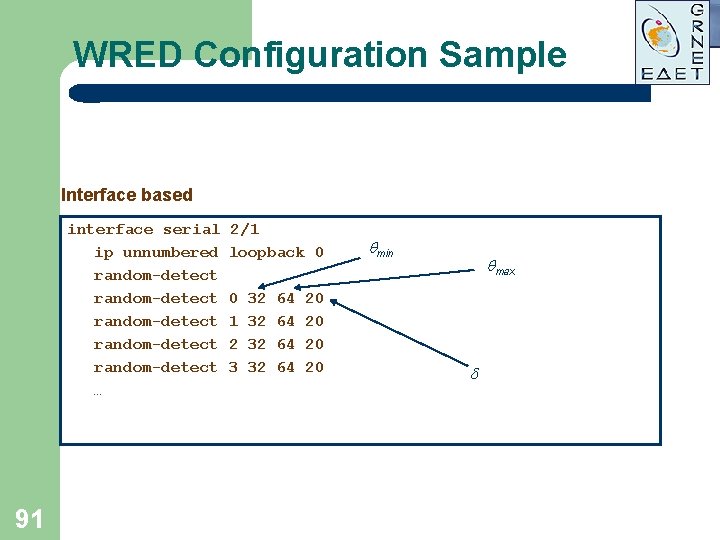
WRED Configuration Sample Interface based interface serial ip unnumbered random-detect random-detect … 91 2/1 loopback 0 0 1 2 3 32 32 64 64 20 20 min max
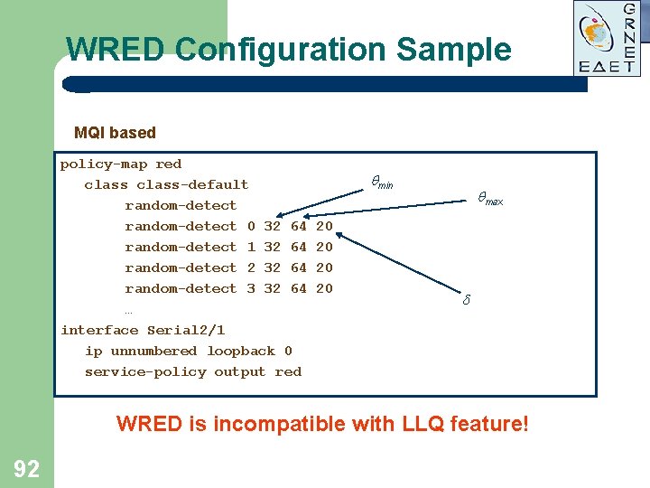
WRED Configuration Sample MQI based policy-map red class-default random-detect 0 32 64 random-detect 1 32 64 random-detect 2 32 64 random-detect 3 32 64 … interface Serial 2/1 ip unnumbered loopback 0 service-policy output red min 20 20 max WRED is incompatible with LLQ feature! 92
Link Optimization 93
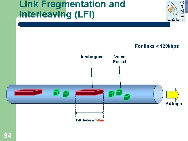
Link Fragmentation and Interleaving (LFI) For links < 128 kbps Jumbogram Voice Packet 64 kbps 1500 bytes 190 ms 94
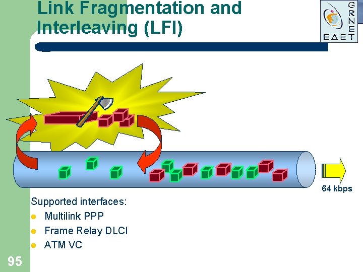
Link Fragmentation and Interleaving (LFI) 64 kbps Supported interfaces: l Multilink PPP l Frame Relay DLCI l ATM VC 95
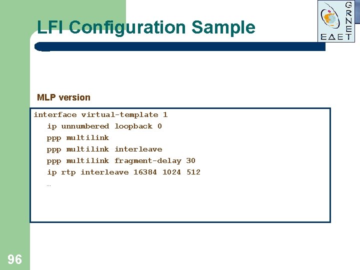
LFI Configuration Sample MLP version interface virtual-template 1 ip unnumbered loopback 0 ppp multilink interleave ppp multilink fragment-delay 30 ip rtp interleave 16384 1024 512 … 96
Signaling 97
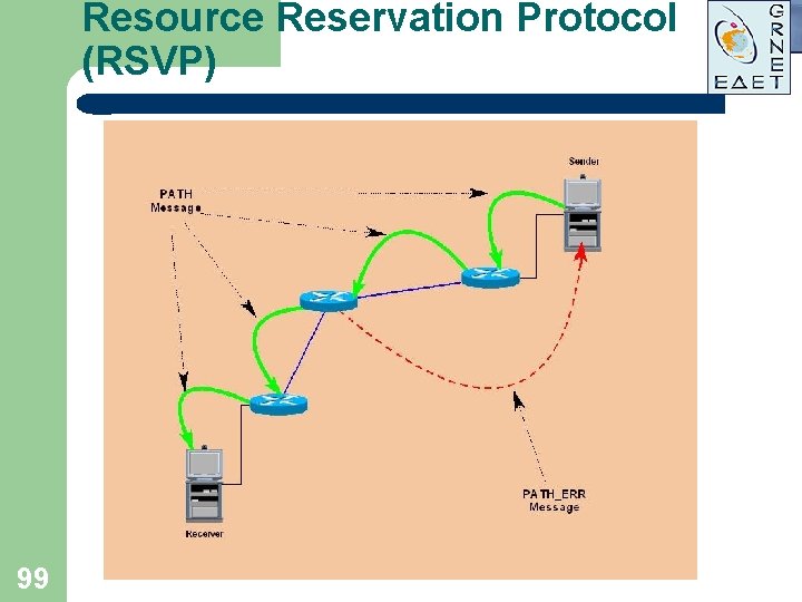
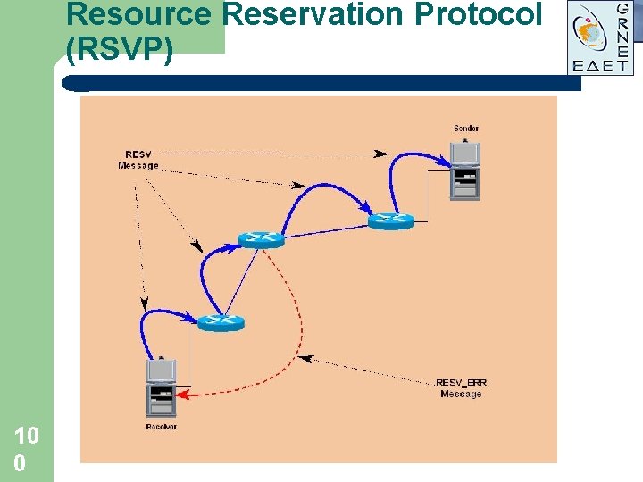
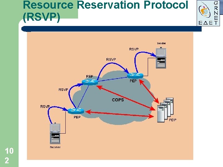
Resource Reservation Protocol (RSVP) l l l 98 End-to-end Qo. S signaling protocol Used to establish dynamic reservations over the network Always establishes simplex reservation Supports unicast and multicast traffic Actually uses WFQ and WRED mechanisms
Resource Reservation Protocol (RSVP) 99
Resource Reservation Protocol (RSVP) 10 0
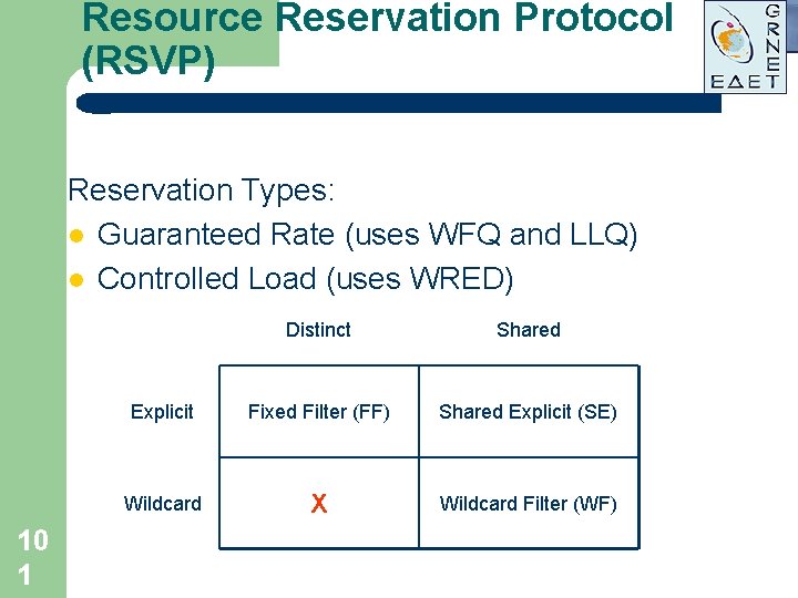
Resource Reservation Protocol (RSVP) Reservation Types: l Guaranteed Rate (uses WFQ and LLQ) l Controlled Load (uses WRED) 10 1 Distinct Shared Explicit Fixed Filter (FF) Shared Explicit (SE) Wildcard X Wildcard Filter (WF)
Resource Reservation Protocol (RSVP) 10 2
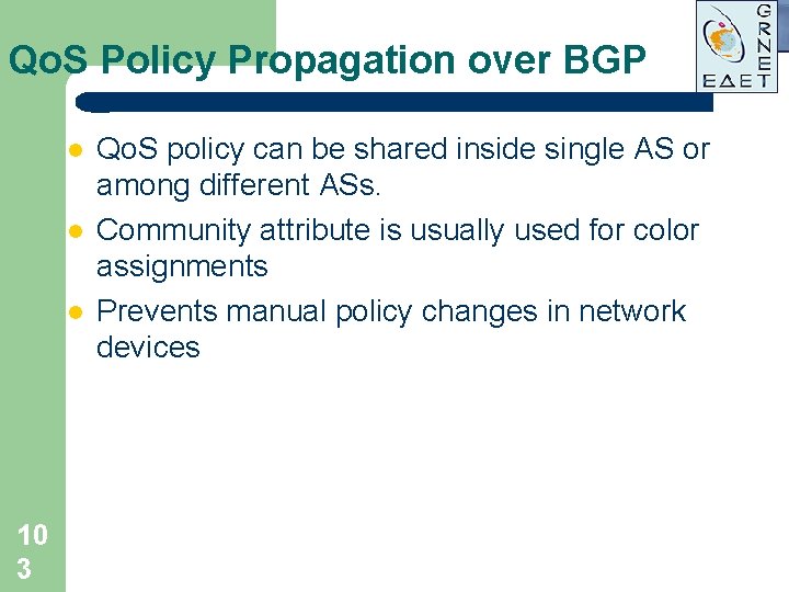
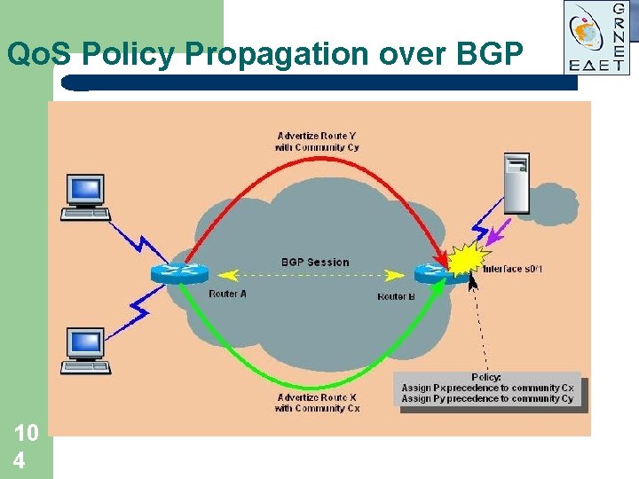
Qo. S Policy Propagation over BGP l l l 10 3 Qo. S policy can be shared inside single AS or among different ASs. Community attribute is usually used for color assignments Prevents manual policy changes in network devices
Qo. S Policy Propagation over BGP 10 4
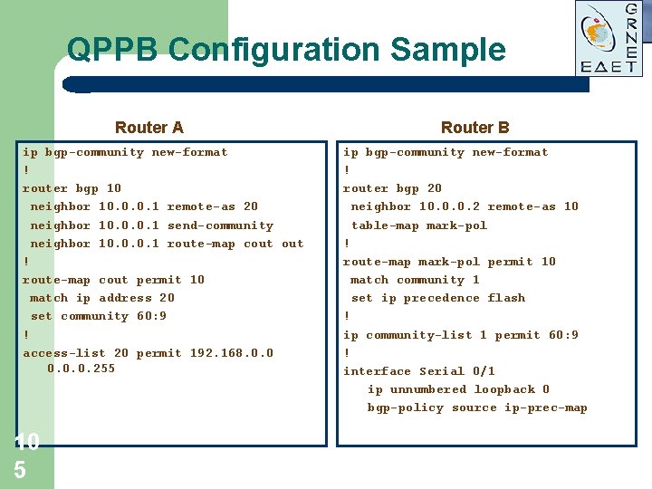
QPPB Configuration Sample Router A ip bgp-community new-format ! router bgp 10 neighbor 10. 0. 0. 1 remote-as 20 neighbor 10. 0. 0. 1 send-community neighbor 10. 0. 0. 1 route-map cout ! route-map cout permit 10 match ip address 20 set community 60: 9 ! access-list 20 permit 192. 168. 0. 0. 0. 255 10 5 Router B ip bgp-community new-format ! router bgp 20 neighbor 10. 0. 0. 2 remote-as 10 table-map mark-pol ! route-map mark-pol permit 10 match community 1 set ip precedence flash ! ip community-list 1 permit 60: 9 ! interface Serial 0/1 ip unnumbered loopback 0 bgp-policy source ip-prec-map
Topics not Covered l l l 10 6 Multiprotocol Label Switching (MPLS) Frame Relay Qo. S ATM Qo. S Distributed Queuing Algorithms Multicast
Conclusion l l l 10 7 Qo. S is not an exotic feature any more Qo. S allows specific applications (Vo. IP, VC) to share network infrastructure with best-effort traffic Qo. S in IP networks simplifies their functionality avoiding Frame Relay and ATM usage
? 10 8 Questions? ? ?