
Ion Source and LEBT Transition from Installation to
Ion Source and LEBT Transition from Installation to Testing and Commissioning Alejandro Garcia Sosa European Spallation Source Lessons Learned - August 28, 2019
Outline • Issues – – – – ISRC Coils Grounding LEBT Solenoids LEBT Chopper IRIS ISRC Repeller Magnetron • Conclusions • Top 3 issues 2
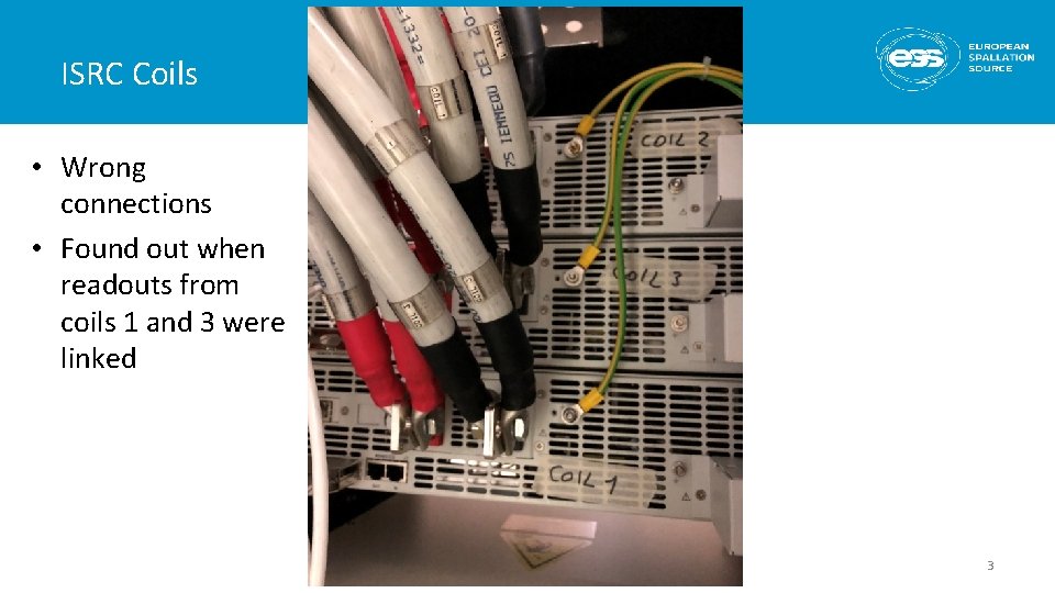
ISRC Coils • Wrong connections • Found out when readouts from coils 1 and 3 were linked 3
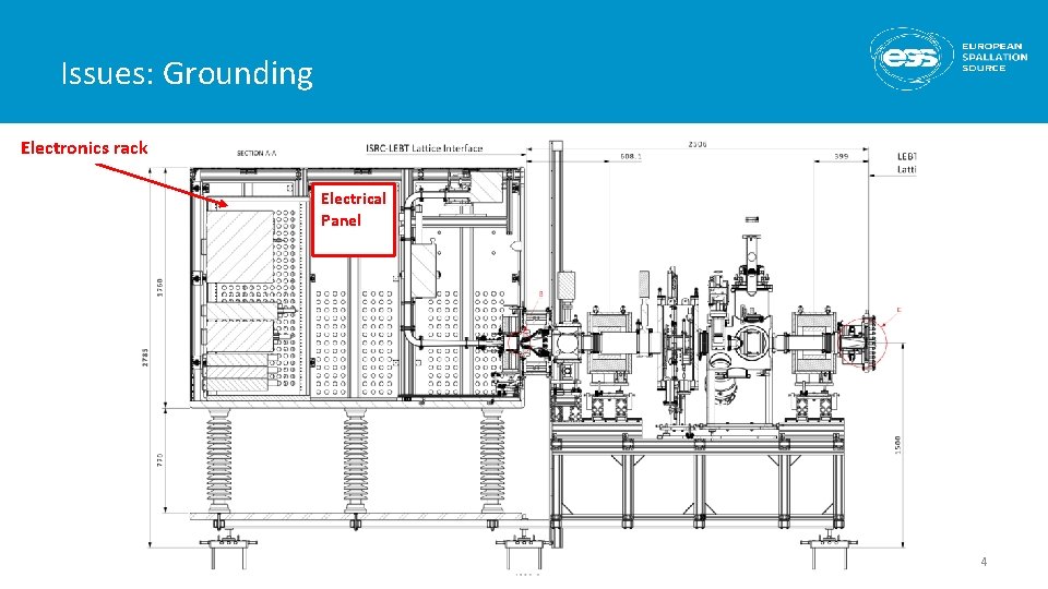
Issues: Grounding Electronics rack Electrical Panel 4
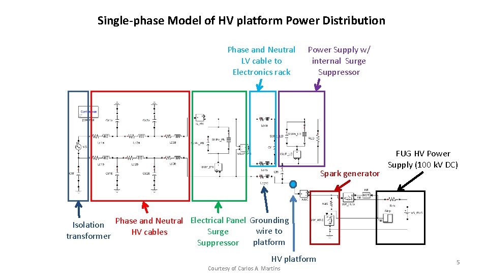
Single-phase Model of HV platform Power Distribution Phase and Neutral LV cable to Electronics rack Power Supply w/ internal Surge Suppressor Spark generator FUG HV Power Supply (100 k. V DC) Electrical Panel Grounding Isolation Phase and Neutral wire to Surge HV cables transformer platform Suppressor HV platform Courtesy of Carlos A. Martins 5
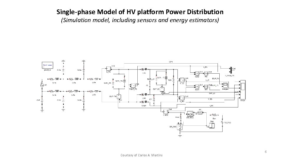
Single-phase Model of HV platform Power Distribution (Simulation model, including sensors and energy estimators) Courtesy of Carlos A. Martins 6
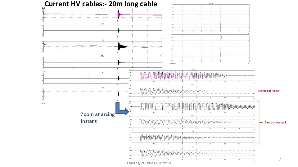
Current HV cables: - 20 m long cable Electrical Panel Zoom at arcing instant Electronics rack Courtesy of Carlos A. Martins 7
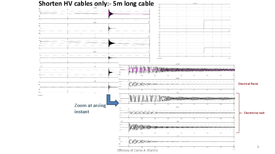
Shorten HV cables only: - 5 m long cable Electrical Panel Zoom at arcing instant Electronics rack Courtesy of Carlos A. Martins 8
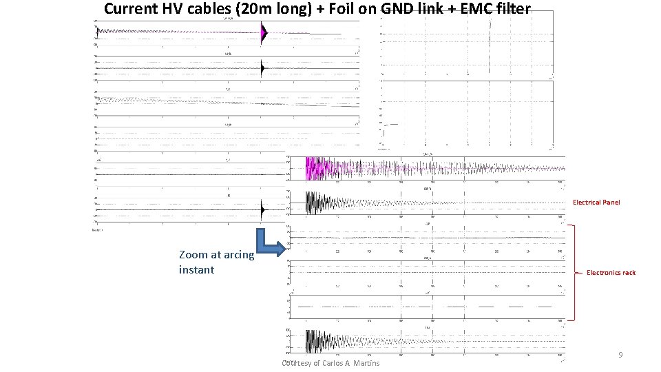
Current HV cables (20 m long) + Foil on GND link + EMC filter Electrical Panel Zoom at arcing instant Electronics rack Courtesy of Carlos A. Martins 9

EMC grounding 10
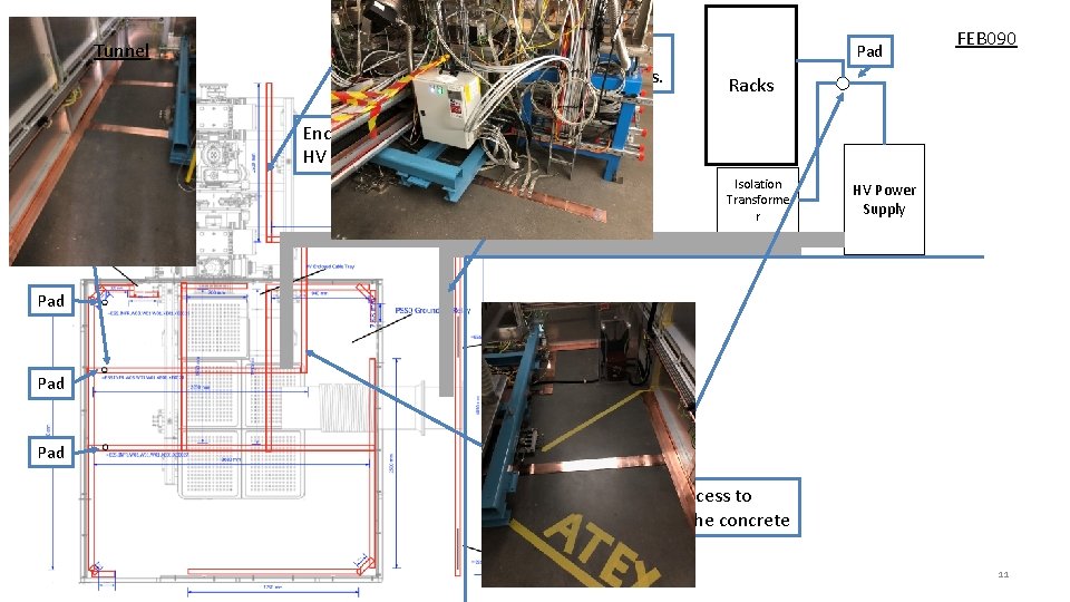
Tunnel Enclosed Cable tray for Isolation transformer cables. Pad FEB 090 Racks Enclosed Cable tray for HV power supply cables Isolation Transforme r HV Power Supply Pad Pads provide access to the mesh beneath the concrete 11
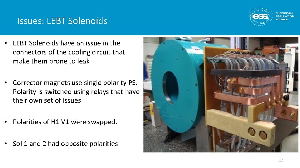
Issues: LEBT Solenoids • LEBT Solenoids have an issue in the connectors of the cooling circuit that make them prone to leak • Corrector magnets use single polarity PS. Polarity is switched using relays that have their own set of issues • Polarities of H 1 V 1 were swapped. • Sol 1 and 2 had opposite polarities 12
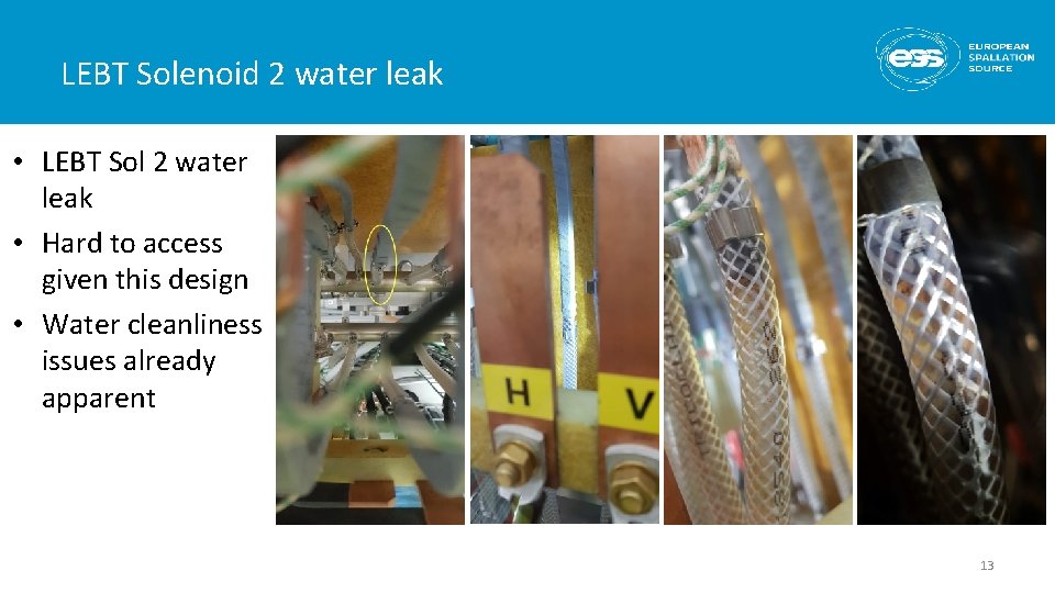
LEBT Solenoid 2 water leak • LEBT Sol 2 water leak • Hard to access given this design • Water cleanliness issues already apparent 13
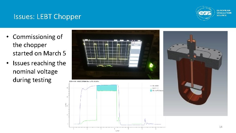
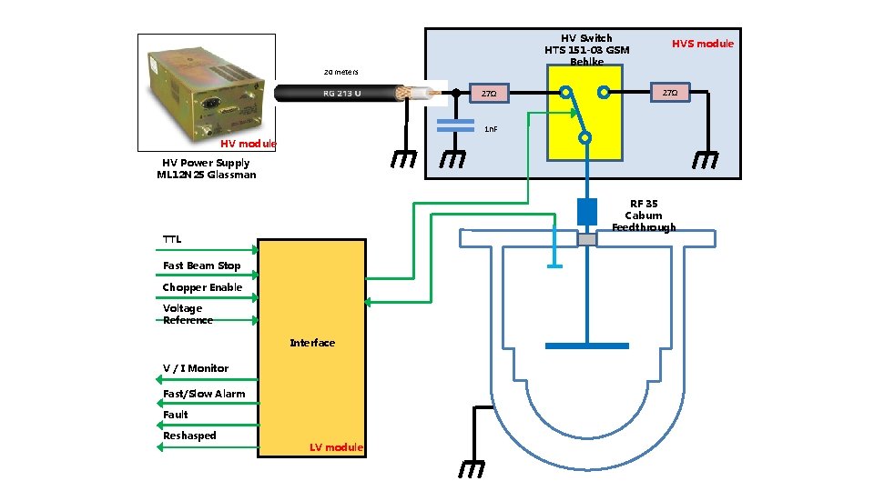
Issues: LEBT Chopper • Commissioning of the chopper started on March 5 • Issues reaching the nominal voltage during testing 14
HV Switch HTS 151 -03 GSM Behlke 20 meters 27Ω HVS module 27Ω 1 n. F HV module HV Power Supply ML 12 N 25 Glassman RF 35 Caburn Feedthrough TTL Fast Beam Stop Chopper Enable Voltage Reference Interface V / I Monitor Fast/Slow Alarm Fault Reshasped LV module
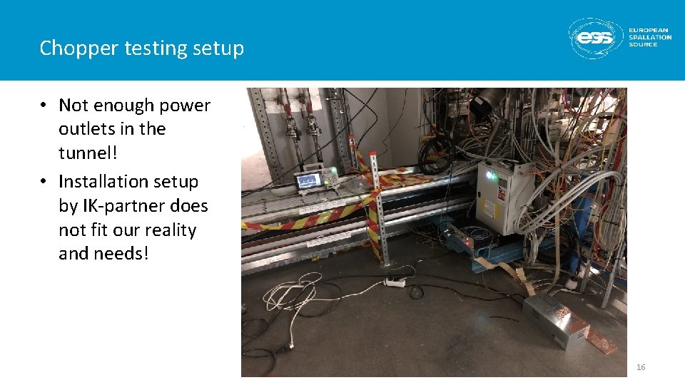
Chopper testing setup • Not enough power outlets in the tunnel! • Installation setup by IK-partner does not fit our reality and needs! 16
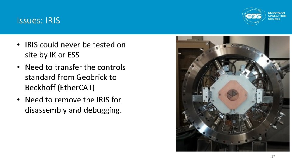
Issues: IRIS • IRIS could never be tested on site by IK or ESS • Need to transfer the controls standard from Geobrick to Beckhoff (Ether. CAT) • Need to remove the IRIS for disassembly and debugging. 17
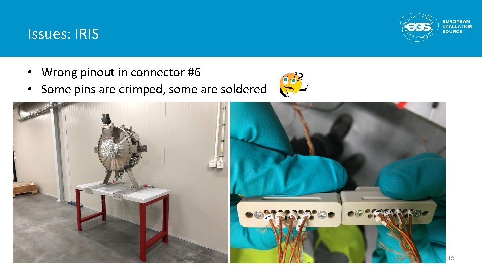
Issues: IRIS • Wrong pinout in connector #6 • Some pins are crimped, some are soldered 18
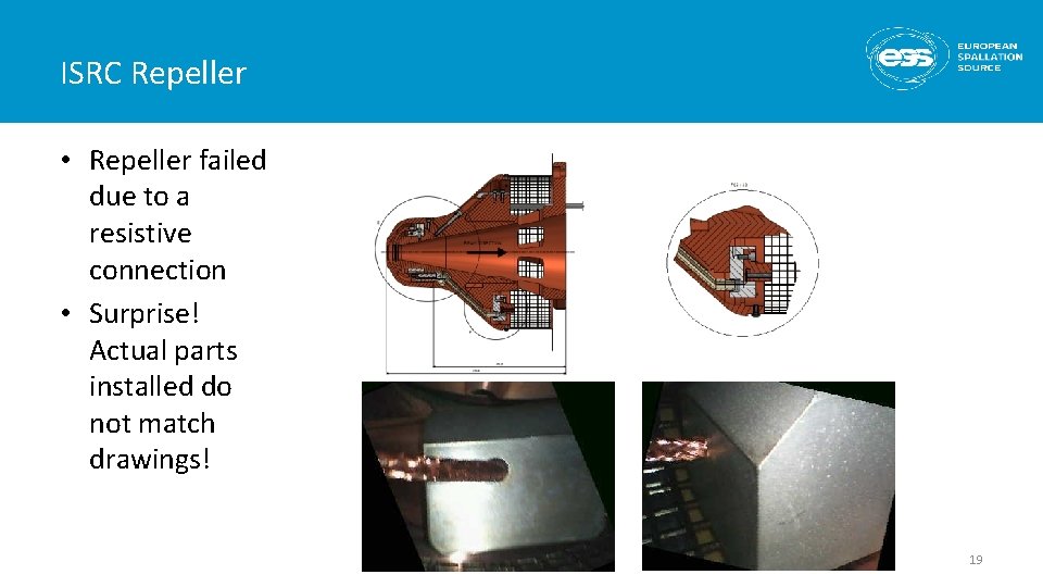
ISRC Repeller • Repeller failed due to a resistive connection • Surprise! Actual parts installed do not match drawings! 19
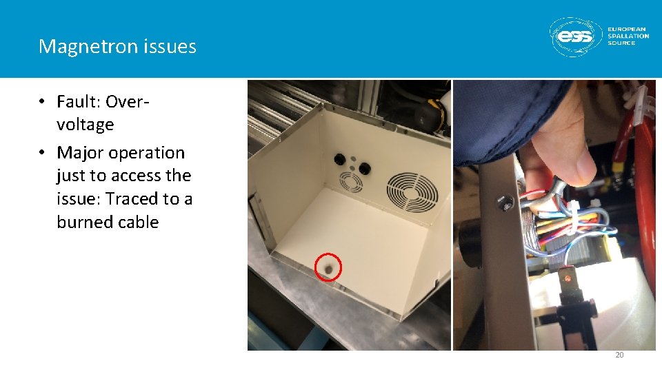
Magnetron issues • Fault: Overvoltage • Major operation just to access the issue: Traced to a burned cable 20
Conclusions • Extensive debugging and troubleshooting of all systems • This could be avoided by allocating sufficient time for local and integrated tests of each system • This had a significant impact on the time available for testing and commissioning of the ISRC & LEBT • Lack of spares 21
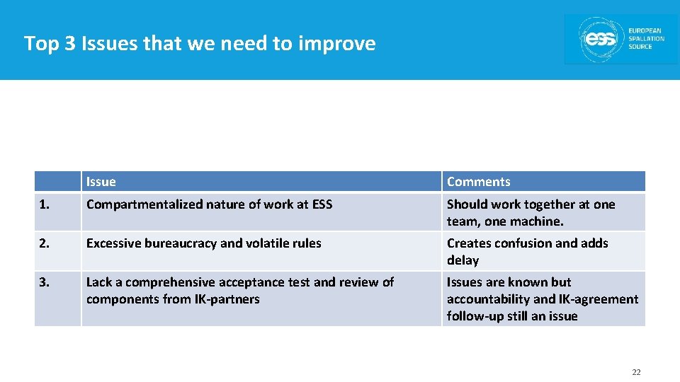
Top 3 Issues that we need to improve Issue Comments 1. Compartmentalized nature of work at ESS Should work together at one team, one machine. 2. Excessive bureaucracy and volatile rules Creates confusion and adds delay 3. Lack a comprehensive acceptance test and review of components from IK-partners Issues are known but accountability and IK-agreement follow-up still an issue 22
Thank you! Questions?
BACKUP SLIDES 24
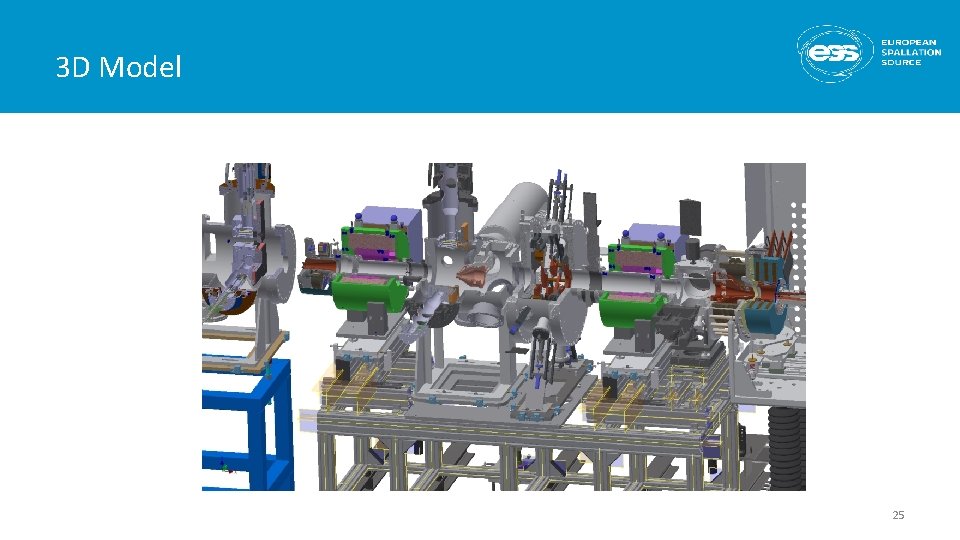
3 D Model 25
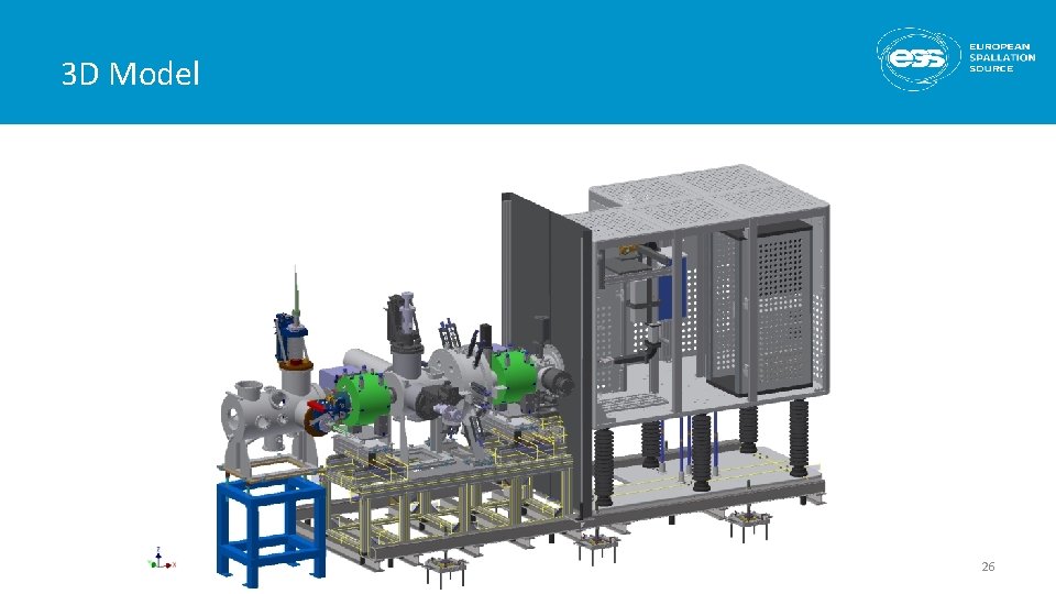
3 D Model 26
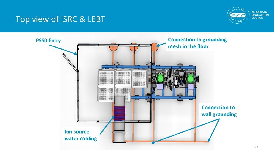
Top view of ISRC & LEBT Connection to grounding mesh in the floor PSS 0 Entry Connection to wall grounding Ion source water cooling 27
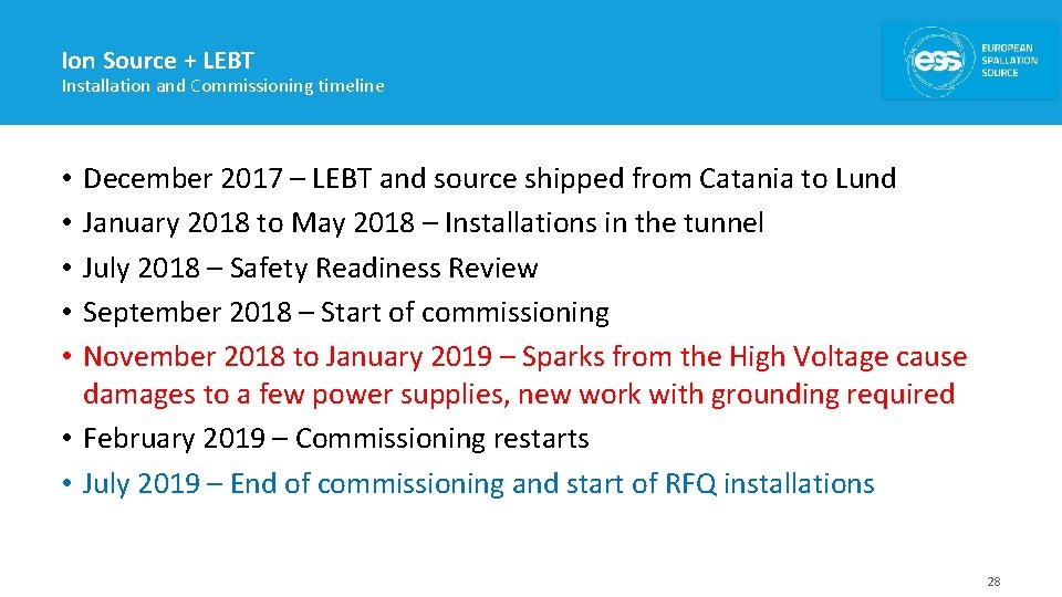
Ion Source + LEBT Installation and Commissioning timeline December 2017 – LEBT and source shipped from Catania to Lund January 2018 to May 2018 – Installations in the tunnel July 2018 – Safety Readiness Review September 2018 – Start of commissioning November 2018 to January 2019 – Sparks from the High Voltage cause damages to a few power supplies, new work with grounding required • February 2019 – Commissioning restarts • July 2019 – End of commissioning and start of RFQ installations • • • 28
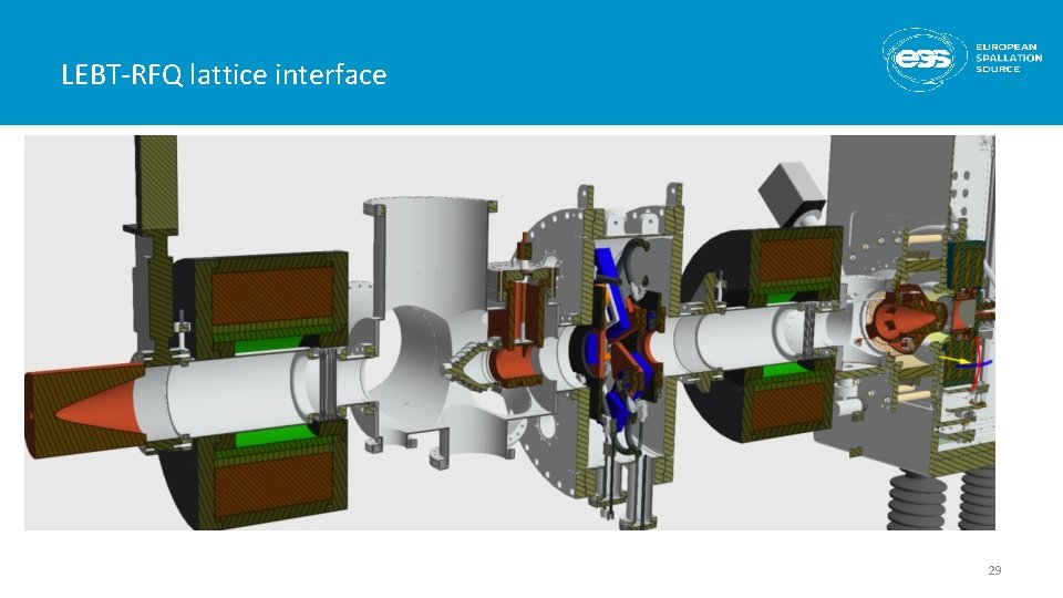
LEBT-RFQ lattice interface 29
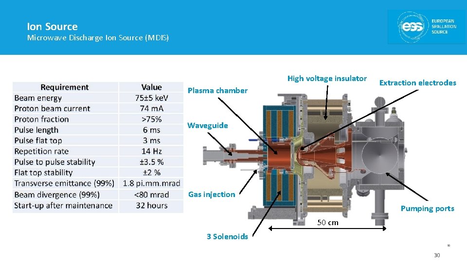
Ion Source Microwave Discharge Ion Source (MDIS) High voltage insulator Plasma chamber Extraction electrodes Waveguide Gas injection Pumping ports 50 cm 3 Solenoids 30 30
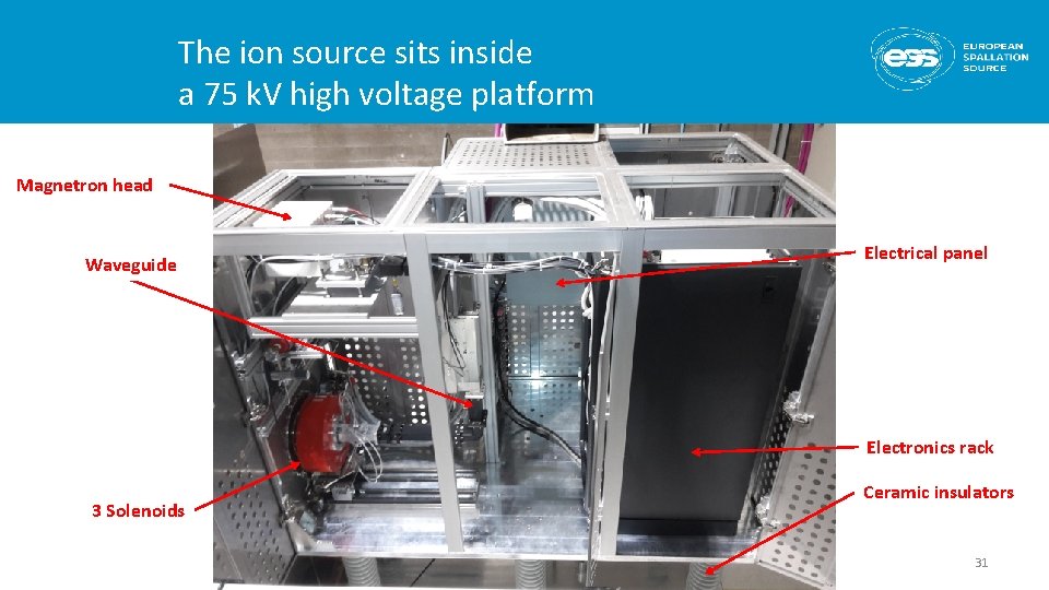
The ion source sits inside a 75 k. V high voltage platform Magnetron head Waveguide Electrical panel Electronics rack 3 Solenoids Ceramic insulators 31
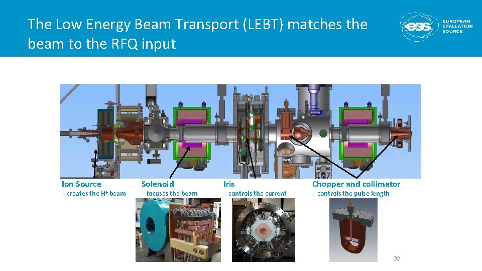
The Low Energy Beam Transport (LEBT) matches the beam to the RFQ input Ion Source – creates the H+ beam Solenoid – focuses the beam Iris – controls the current Chopper and collimator – controls the pulse length 32
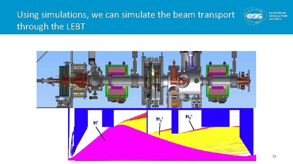
Using simulations, we can simulate the beam transport through the LEBT H+ H 2+ H 3+ 33
- Slides: 33