IO Organization 1 Agenda Single bus architecture n

第四章 I/O Organization 1

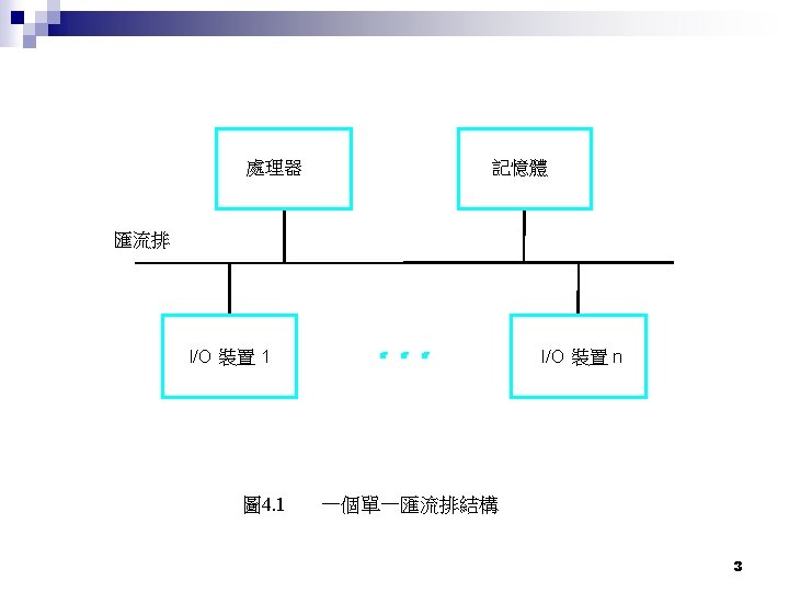
Agenda Single bus architecture n I/O Bus n ¨ Address lines ¨ Data lines ¨ Control lines n I/O addressing ¨ Memory-mapped ¨ Isolated I/O 2

System resources n Every I/O device will use some system resources ¨ IRQ n Hardware interrupt ¨ DMA Channels n For direct memory access ¨ I/O ports (I/O addresses) n Low memory area n For communication between devices and cpu ¨ I/O memory n Upper memory area(384 K) n For device driver mapped from BIOS n For temporary data storage 4

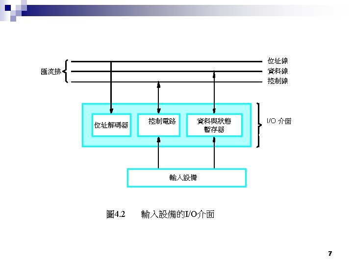
I/O BUS n Address lines ¨ Address n Data lines ¨ Data n the I/O devices put from device or cpu Control lines ¨ Read/write ¨ When data is ready 5

I/O addressing n Memory-mapped I/O ¨ I/O device share the same address space with memory n Isolated I/O ¨ Special Instruction I/O ¨ the 8086 used IN and OUT to read and write to I/O devices ¨ A output pin of CPU differentiate the address to memory or devices 6
")
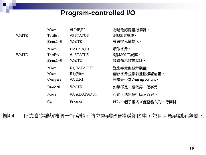
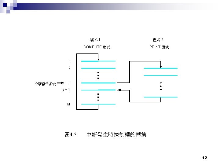
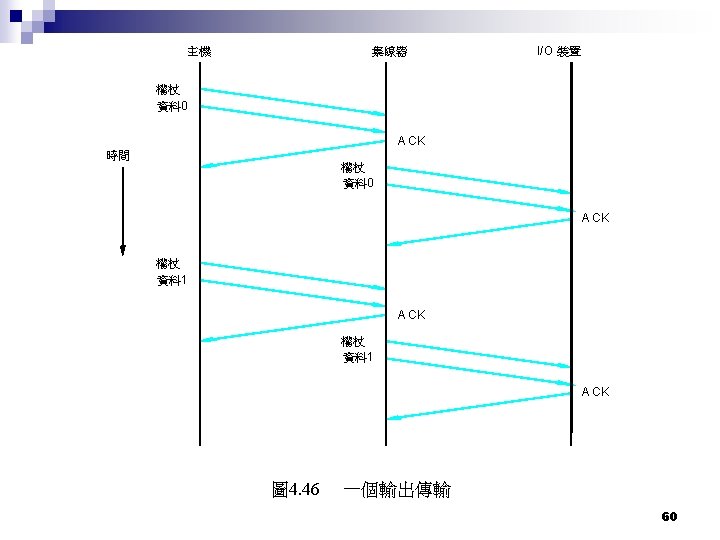
Input Output Techniques Program-controlled I/O n Interrupt driven I/O n DMA (Direct Memory Access) n 9

Interrupt driven I/O Refer to Page 4 -22 圖 4. 9 11

Avoid infinite interrupt n Mask interrupt ¨ Ignore interrupt until entering first instruction of interrupt service routine ¨ Then disable interrupt in the first instruction of interrupt service routine ¨ Enable interrupt in the last instruction of interrupt service routine 13

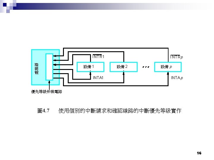
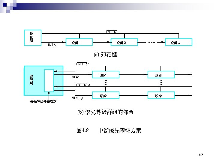
Multiple devices interrupt n Prioritize the devices ¨ Eq irq 0 > irq 1> irq 2. . 14

Interrupt Vectors 15
 n")
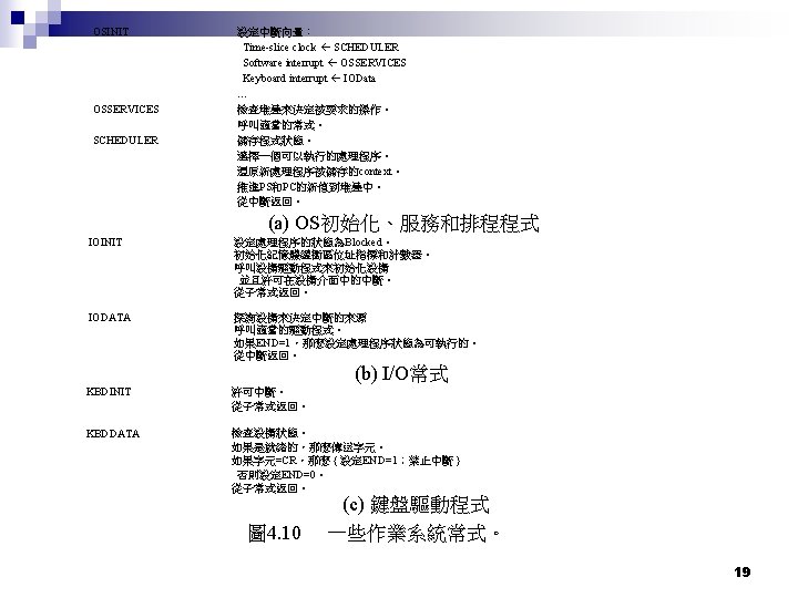
Software interrupt System call from applications n A interrupted by scheduler (via clock) n Context switching n Scheduler selects B n Before A’s time slice due, A requests I/O (eg. Keyboard input), A will issue system call to OS and OS will finally call I/O routine n 18
 n n n CPU doesn’t involve data transferring except and")
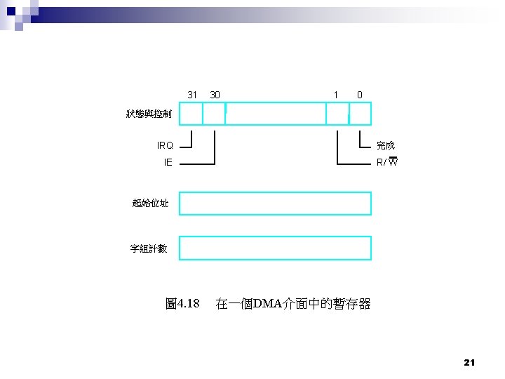
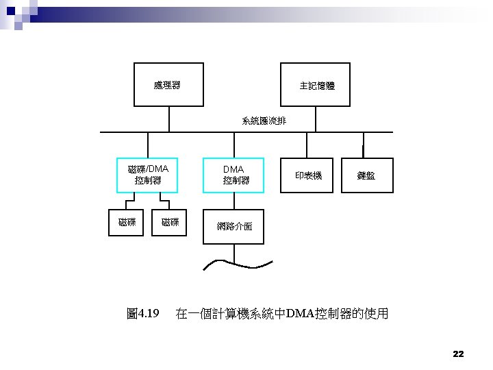
Direct Memory Access (DMA) n n n CPU doesn’t involve data transferring except and the beginning and the end DMAC(DMA Controller) in charge of data transferring CPU tells DMAC ¨ ¨ ¨ n n The starting address of word to be transferred Work counts Direction (read or write) When DMA is transferring data, the request AP is blocked by OS, at the same time CPU can execute other programs When DMAC done work, it will interrupt CPU and OS will resume the blocked AP then the scheduler can schedule it 20

23

CPU involved 24

25

26

DMA mode n Burst Mode DMA – Here the DMA machine simply takes over control of the Bus ¨ makes the data transfer at top speed ¨ hands control back to the CPU. ¨ This is fast, but the CPU is stopped dead for the duration of the transfer. n SUMMARY: Take control of BUS. ¨ Stop the CPU ¨ Send all the data to Memory ¨ Restore BUS control to CPU ¨ 27

DMA mode n Cycle Stealing ¨ ¨ ¨ In the course of a normal program the CPU spends a lot of time executing internal CPU instructions (e. g. add ax, bx, inc bx, jnz fred) During the execute phase of these instructions the CPU does not need control of the Bus or access to memory. In cycle stealing mode the DMA machine has the ability to “steal” bus cycles for its own data transfer, stopping the CPU. But it can also use those bus cycles that the CPU doesn’t need. This cycle stealing approach slows down both the CPU and the DMA, but is more efficient overall. Not an interrupt, CPU does not switch context CPU suspended just before it accesses bus i. e. before an operand or data fetch or a data write n n n SUMMARY: Take every second cycle off the CPU to use the BUS Also take any cycle where the CPU is not using the BUS (also known as Hidden DMA) 28

29

Bus L i n e ? D M A Typical Defa ult Use Other Common Uses 0 no Memory Refre sh None 1 8/16 b i t Sound card (low DMA) SCSI host adapters, ECP parallel ports, tape accelerator cards, network cards, voice modems 2 8/16 b i t Floppy disk contr oller Tape accelerator cards 3 8/16 b i t None 4 no None; casc ade for DMA s 0 -3 5 16 -bit o n l y Sound card (high DMA) 6 16 -bit o n l None ECP parallel ports, SCSI host adapters, tape accelerator cards, sound card (low DMA), network cards, voice modems, hard disk controller on old PC/XT None SCSI host adapters, network cards Sound cards (high DMA), network cards 30

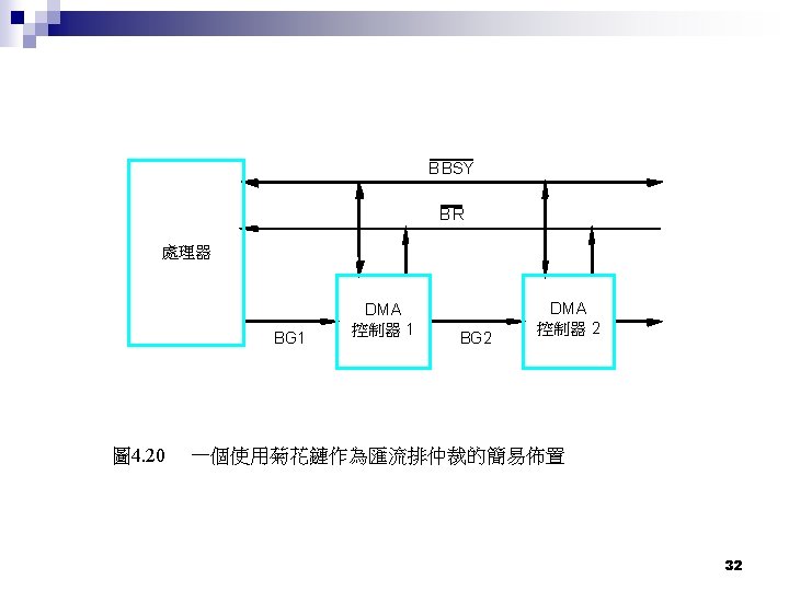
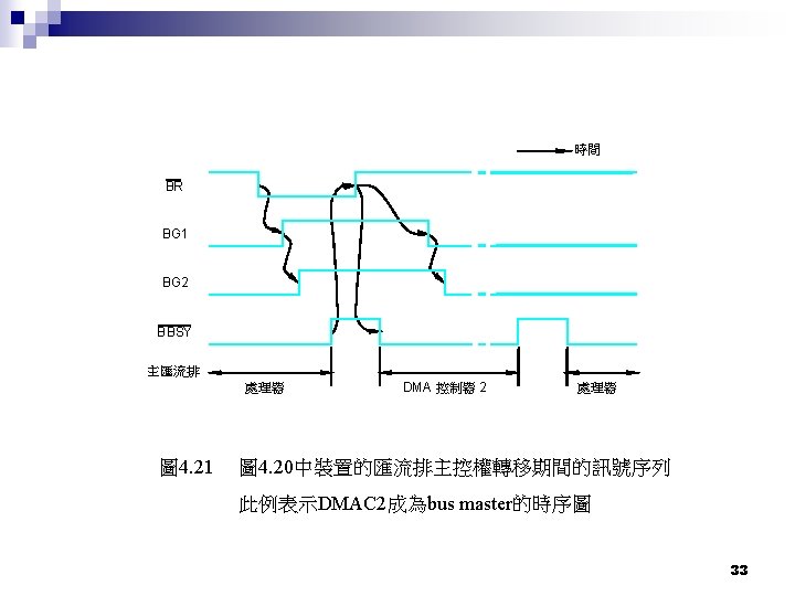
BUS Arbiter Who becomes bus master? n Centralized n distributed n 31

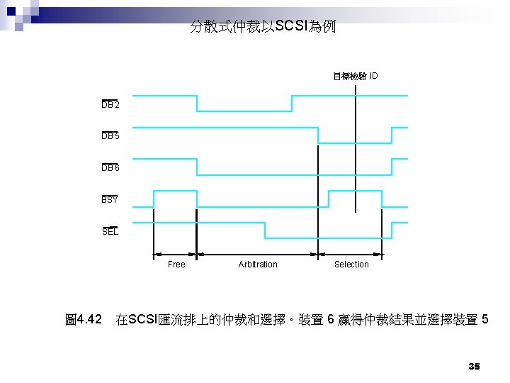
V cc A RB 3 A RB 2 A RB 1 A RB 0 Start-Arbitration O. C. 0 1 0 1 1 1 設備 A 的介面電路 圖 4. 22 一個分散式仲裁方案 34

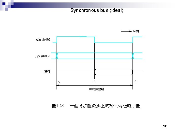
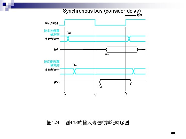
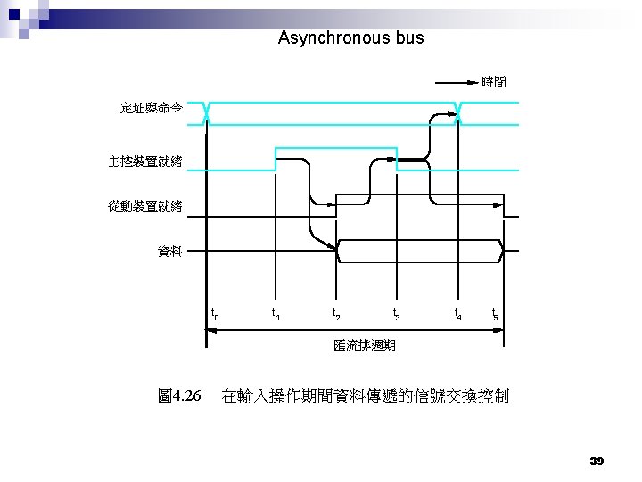
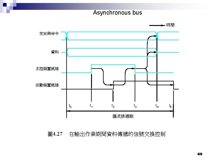
BUS timing n Synchronous bus Includes a clock in the control lines ¨ A fixed protocol for communication that is relative to the clock ¨ Advantage: involves very little logic and can run very fast ¨ Disadvantages: ¨ n n n Every device on the bus must run at the same clock rate To avoid clock skew, they cannot be long if they are fast Asynchronous It is not clocked (using master-ready and slave-ready instead) ¨ It can accommodate a wide range of devices ¨ It can be lengthened without worrying about clock skew ¨ It requires a handshaking protocol ¨ 36

Parallel port vs serial port n serial port ¨ ¨ ¨ n Information is transferred in or out one bit at a time RS 232 USB Firewire (IEEE 1394) Serial ATA (Disk) parallel port ¨ ¨ ¨ data is transferred in or out in parallel Printer port microprocessor to communicate with peripherals PCI SCSI Parallel ATA (Disk) 41
 ¨ Short and high")
Types of Buses n n n Processor-Memory Bus (design specific) ¨ Short and high speed ¨ Only need to match the memory system n Maximize memory-to-processor bandwidth ¨ Connects directly to the processor ¨ Optimized for cache block transfers I/O Bus (industry standard) ¨ Usually is lengthy and slower ¨ Need to match a wide range of I/O devices ¨ Connects to the processor-memory bus or backplane bus Backplane Bus (standard or proprietary) ¨ Backplane: an interconnection structure within the chassis ¨ Allow processors, memory, and I/O devices to coexist ¨ Cost advantage: one bus for all components 42

A Computer System with One Bus: Backplane Bus Processor Memory I/O Devices n n A single bus (the backplane bus) is used for: ¨ Processor to memory communication ¨ Communication between I/O devices and memory Advantages: Simple and low cost Disadvantages: slow and the bus can become a major bottleneck Example: IBM PC - AT 44
 IBM-PC and PC-XT: 8")
Buses in PC-XT and PC-AT n ISA (Industry Standard Architecture) IBM-PC and PC-XT: 8 bits at 4. 77 MHz, directly connect to 8088, 2 -stage bus cycle (2. 38 Mbyte/sec bus bandwidth) ¨ AT bus: extension slot + 8 bit ISA n 16 bits at 8. 33 MHz for 80286 timer, ¨ BIOS int. contl. bus buffer ISA bus CPU DRAM contrl. DMA contrl. DRAM expansion slots 45

A Two-Bus System Processor Memory Bus Adaptor I/O Bus n n Bus Adaptor I/O Bus I/O buses tap into the processor-memory bus via bus adaptors: ¨ Processor-memory bus: mainly for processor-memory traffic ¨ I/O buses: provide expansion slots for I/O devices Apple Macintosh-II ¨ Nu. Bus: Processor, memory, and a few selected I/O devices ¨ SCCI Bus: the rest of the I/O devices 46
 n n 16 -bit ISA cannot support Window applications --- video")
Buses in PC(486) n n 16 -bit ISA cannot support Window applications --- video data VESA LB (local bus) -- linked to 486 local bus, 33 MHZ, DRAM 32 bits 486 CPU local bus L 2 cache ISA bridge ISA bus buffer video card LAN adapter HDD contrl. expansion slots 47

A Three-Bus System Processor Memory Bus Adaptor Backplane Bus Adaptor n n I/O Bus A small number of backplane buses tap into the processor-memory bus ¨ Processor-memory bus is only used for processor-memory traffic ¨ I/O buses are connected to the backplane bus Advantage: loading on the processor bus is greatly reduced 48
 Pentium CPU n A three-bus system host bus PCI chipset")
Buses in PC (Pentium) Pentium CPU n A three-bus system host bus PCI chipset PCI bridge L 2 Cache Data bus Memory PCI bus Video card LAN adapter PCI/ISA bridge SCSI adapter HDD CD-ROM IDE controller monitor ISA bus Super. IO chip Modem sound card 49

50

Processor/Memory Bus PCI Bus I/O Busses 51
,")
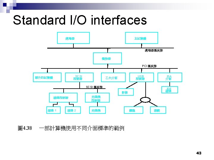
PCI Bus n n n 1992 by Intel Support Pn. P (plug and play), but is not popular until windows 95 release Support memory, I/O and configuration addressing, where configuration address is for Pn. P PCI is a 64 -bit bus, though it is usually implemented as a 32 -bit bus. It can run at clock speeds of 33 or 66 MHz. At 32 bits and 33 MHz, it yields a throughput rate of 133 MBps. PCI-Express ¨ ¨ n 3 GIO, 2. 5 Bb/s 1394 b, USB 2. 0, Infini. Band Gigabit Ethernet PCI-X (PCI extended) ¨ 133 MBps to as much as 1 GBps. 52

Requirements for Plug and Play n n System Hardware ¨ system chipset and system bus controllers, must be capable of handling Pn. P devices Peripheral Hardware ¨ n The System BIOS ¨ n These devices must be Pn. P-aware so that they are capable of identifying themselves when requested, and able to accept resource assignments from the system when they are made. Routines built into the BIOS perform the actual work of collecting information about the different devices and determining what should use which resources. The BIOS also communicates this information to the operating system, which uses it to configure its drivers and other software to make the devices work correctly. The Operating System ¨ Finally, the operating system must be designed to work with the BIOS (and thus indirectly, with the hardware as well). support is Windows 95. 53
 SCSI-1 Wide SCSI-2 Fast Wide SCSI")
SCSI Transfer Mode Defining Standard "Regular" SCSI (SCSI-1) SCSI-1 Wide SCSI-2 Fast Wide SCSI Ultra SCSI-2 SCSI-3 / SPI Bus Width (bits) 8 16 8 Bus Speed (MHz) 5 5 10 10 20 Through- put (MB/s) 5 10 10 20 20 Special Features Cabling 50 -pin 68 -pin 50 -pin Signaling Method Maximum Devices Per Bus Maximum Cable Length (m) SE 8 6 HVD 8 25 SE 16 6 HVD 16 25 SE 8 3 HVD 8 25 SE 16 3 HVD 16 25 8 1. 5 4 3 8 25 8 1. 5 4 3 16 25 SE HVD Wide Ultra SCSI SE SCSI-3 / SPI 16 20 40 68 -pin HVD 54
 Bus Speed (MHz) Through- put (MB/s)")
SCSI Transfer Mode Defining Standard Bus Width (bits) Bus Speed (MHz) Through- put (MB/s) Special Features Cabling Ultra 2 SCSI Signaling Method LVD SCSI-3 / SPI-2 8 40 40 50 -pin HVD Wide Ultra 2 SCSI LVD SCSI-3 / SPI-2 16 40 80 68 -pin HVD At least one of Fast-80, CRC, DV, QAS, Packet 68 -pin 160 Fast-80, CRC, DV 68 -pin LVD SCSI-3 / SPI-3 16 Ultra 160(/m ) SCSI-3 / SPI-3 16 Ultra 160+ SCSI-3 / SPI-3 16 40 (DT) 160 Fast-80, CRC, DV, QAS, Packet Ultra 320 SCSI-3 / SPI-4 16 80 (DT) 320 Fast-160, ? Ultra 3 SCSI 40 (DT) 160 Maximum Devices Per Bus Maximum Cable Length (m) 8 12 2 25 8 25 16 12 2 25 16 12 2 25 LVD 55

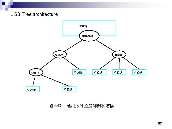
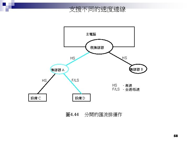
USB n Data rate ¨ USB n n Low speed 1. 5 Mb/s Full speed 12 Mb/s ¨ USB n n 1. 1 2. 0 High speed 480 Mb/s 127 devices (用 7 bits表示連接的設備) Pn. P It is expected to completely replace serial and parallel ports 56
 封包辨識字欄位 8 位元 7 PID")
PID 0 PID 1 PID 2 PID 3 (a) 封包辨識字欄位 8 位元 7 PID ADDR 4 ENDP 5 CRC 16 (b) 標記封包IN或是OUT 位元 8 0 到 8192 16 PID D A TA CRC 16 (c) 資料封包 圖 4. 45 USB封包型式 59
- Slides: 60