
Investigations into the dynamics of bolted joints Hugh

Investigations into the dynamics of bolted joints Hugh Goyder Centre for Defence Engineering Cranfield University Defence Academy of the United Kingdom Shrivenham SN 6 8 LA h. g. d. goyder@cranfield. ac. uk 4 July 2019 www. cranfield. ac. uk
Overview • Joints and dynamics: Bolted joints can absorb vibrational energy. Damping can mitigate resonant vibration. Joints can be main source of damping. • What happens inside a bolted joint? • Two sorts of joint behaviour • Recent results © Cranfield University
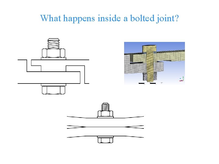
What happens inside a bolted joint? © Cranfield University
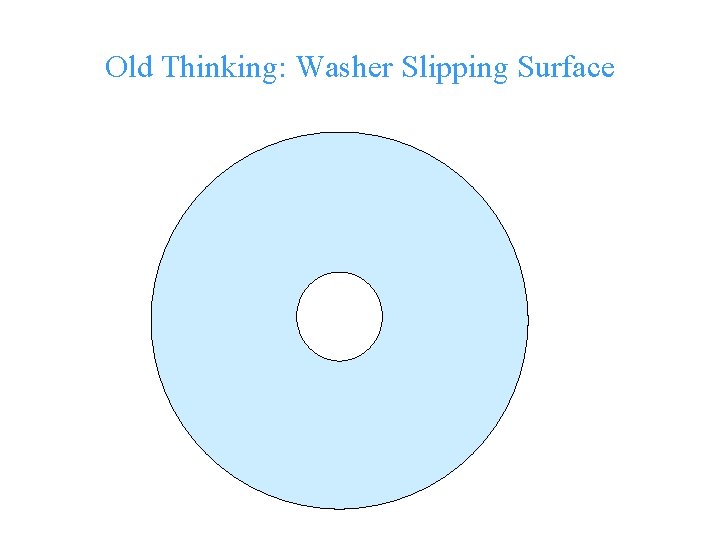
Old Thinking: Washer Slipping Surface © Cranfield University
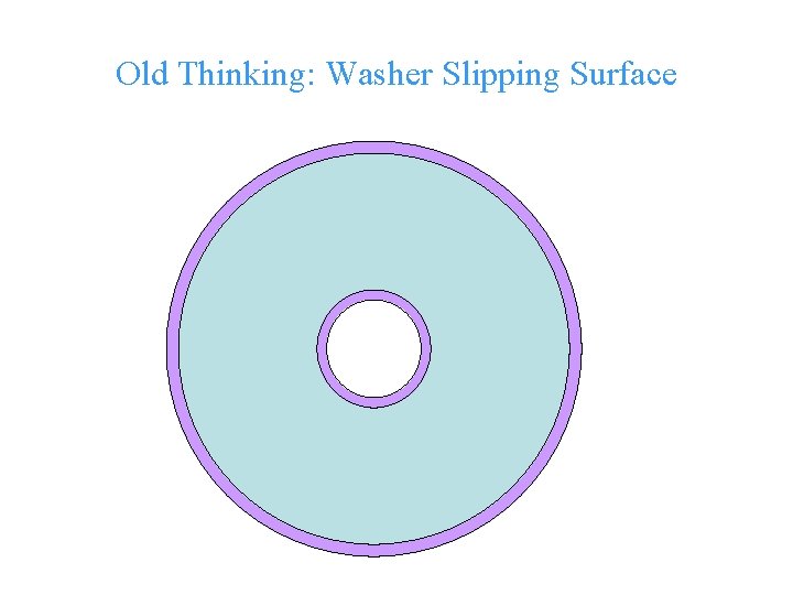
Old Thinking: Washer Slipping Surface © Cranfield University

Two types of bolted joint A joint with a limited contact patch (complete contact). A joint with flat surfaces which has a gap surrounding the contact patch (receding contact). © Cranfield University
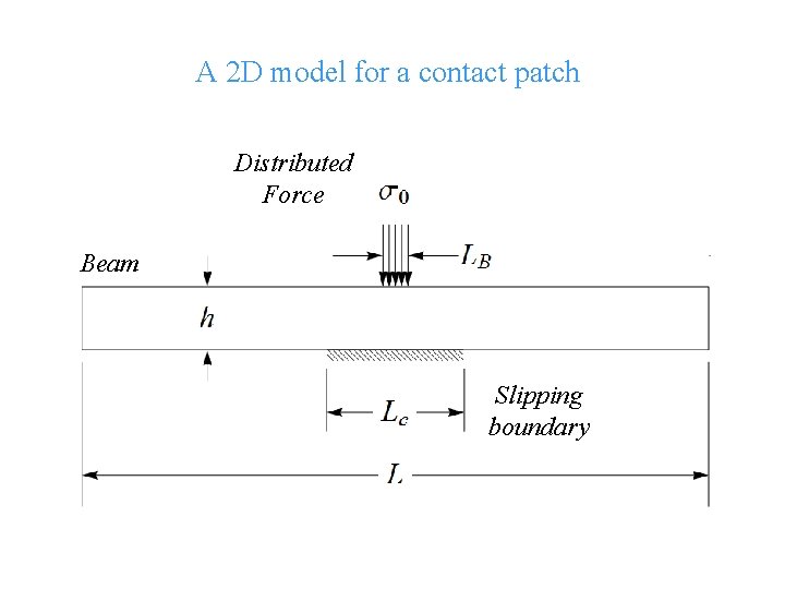
A 2 D model for a contact patch Distributed Force Beam Slipping boundary © Cranfield University
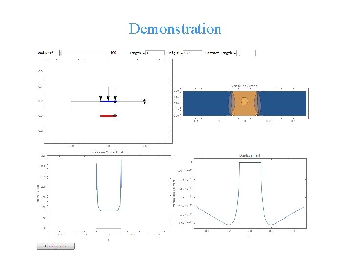
Demonstration © Cranfield University
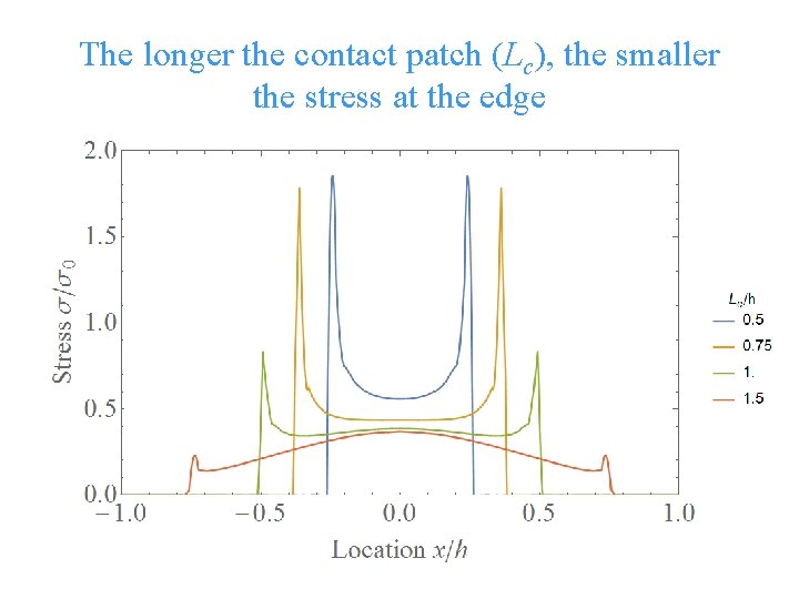
The longer the contact patch (Lc), the smaller the stress at the edge © Cranfield University
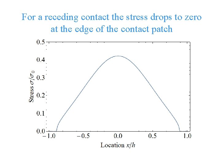
For a receding contact the stress drops to zero at the edge of the contact patch © Cranfield University
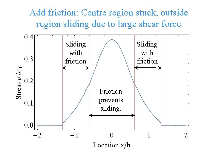
Add friction: Centre region stuck, outside region sliding due to large shear force Sliding with friction Friction prevents sliding. © Cranfield University
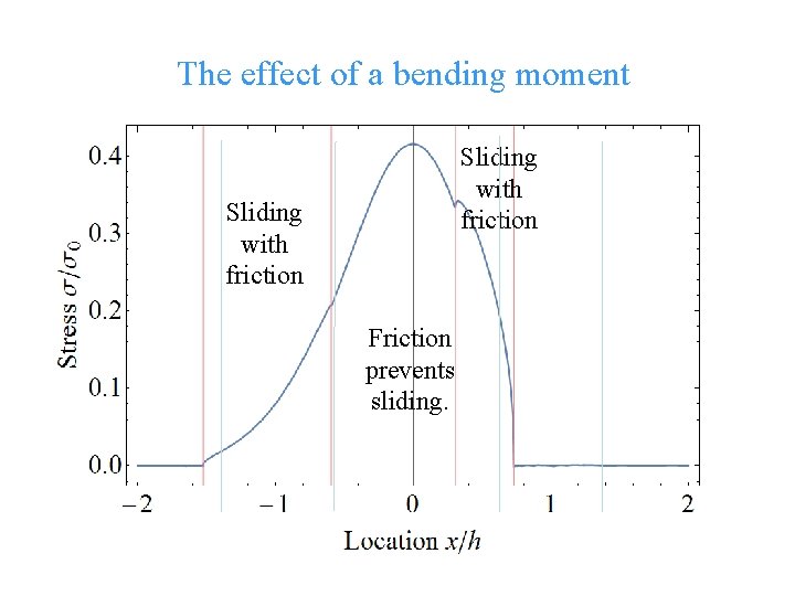
The effect of a bending moment Sliding with friction Friction prevents sliding. © Cranfield University
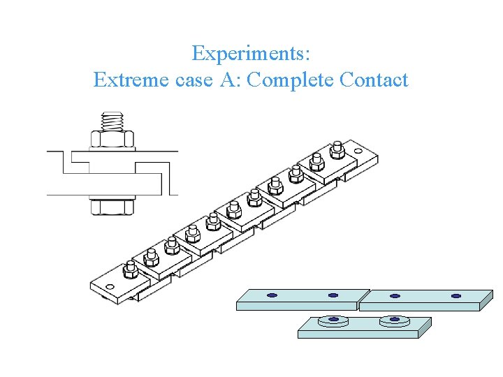
Experiments: Extreme case A: Complete Contact © Cranfield University
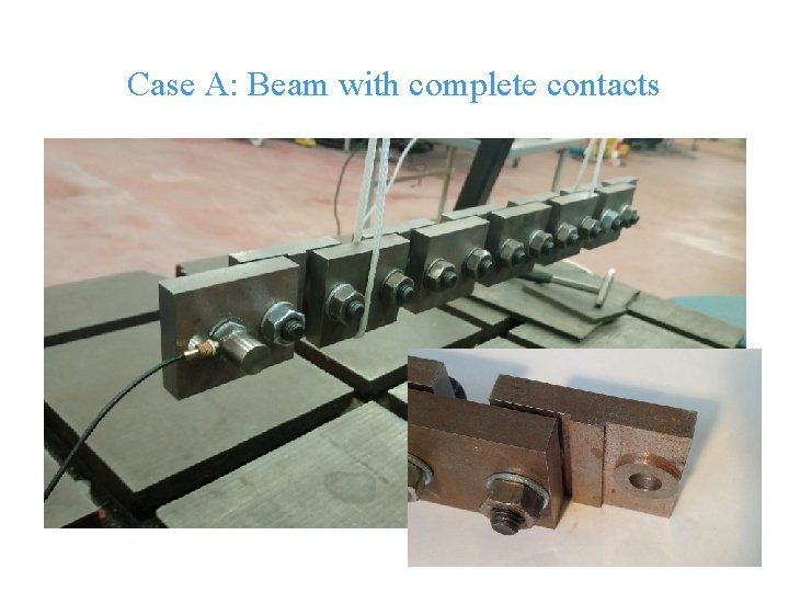
Case A: Beam with complete contacts © Cranfield University
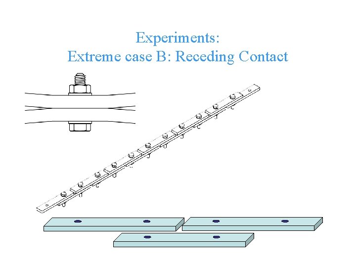
Experiments: Extreme case B: Receding Contact © Cranfield University
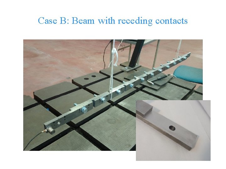
Case B: Beam with receding contacts © Cranfield University
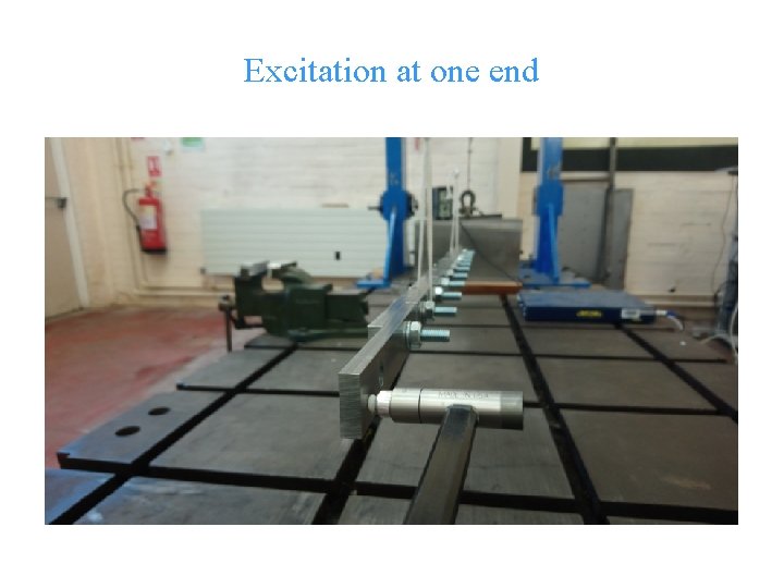
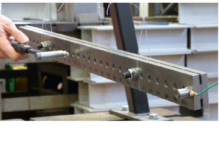
Excitation at one end © Cranfield University
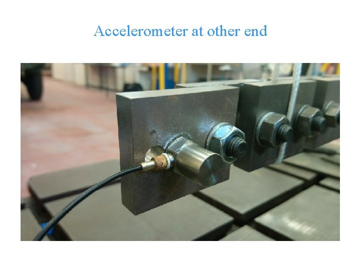
Accelerometer at other end © Cranfield University
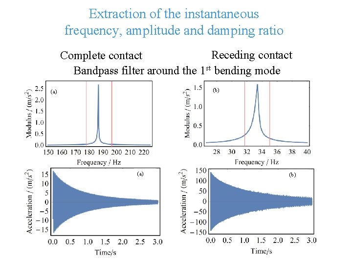
Extraction of the instantaneous frequency, amplitude and damping ratio Receding contact Complete contact Bandpass filter around the 1 st bending mode (b) (a) (b) © Cranfield University
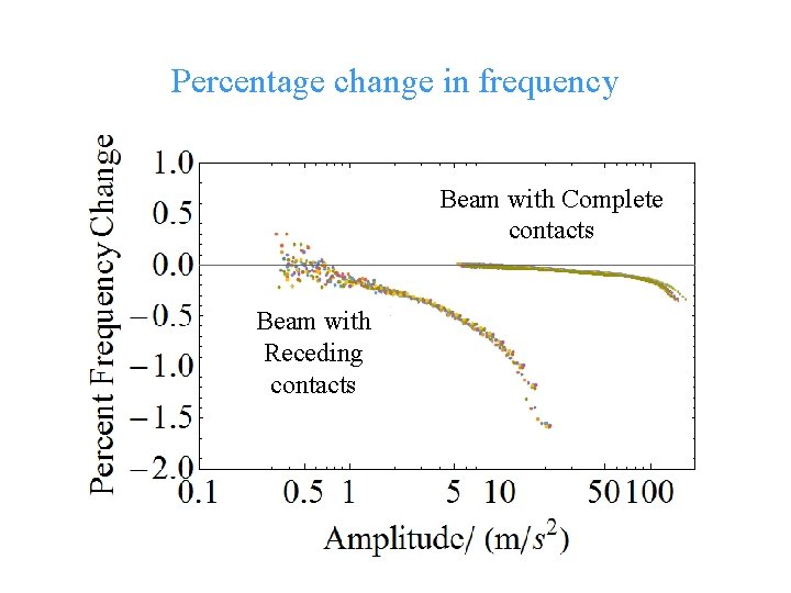
Percentage change in frequency Beam with Complete contacts Beam with Receding contacts © Cranfield University
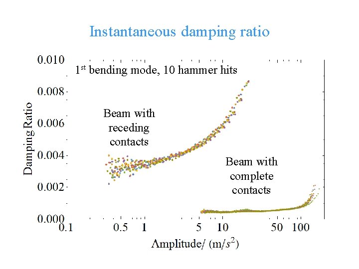
Instantaneous damping ratio 1 st bending mode, 10 hammer hits Beam with receding contacts Beam with complete contacts © Cranfield University
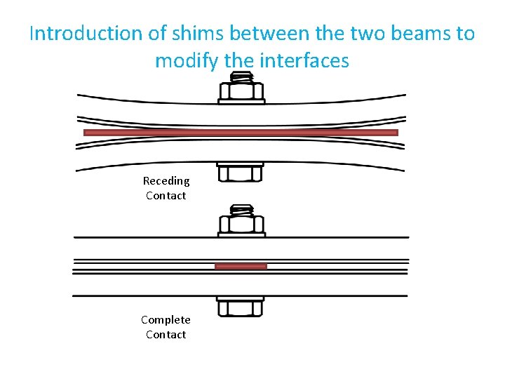
Introduction of shims between the two beams to modify the interfaces Receding Contact Complete Contact
© Cranfield University
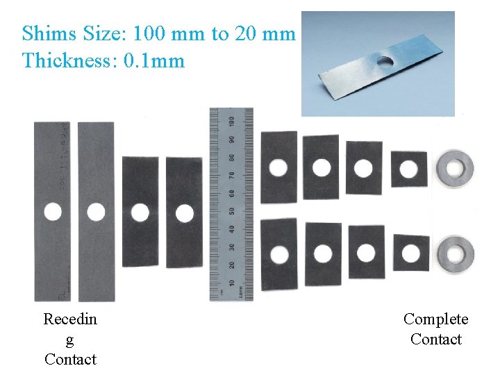
Shims Size: 100 mm to 20 mm Thickness: 0. 1 mm Recedin g Contact Complete Contact © Cranfield University
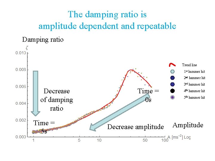
The damping ratio is amplitude dependent and repeatable Damping ratio Trend line 1 st hammer hit 2 nd hammer hit 3 rd hammer hit Decrease of damping ratio Time = 5 s Time = 0 s Decrease amplitude 4 th hammer hit 5 th hammer hit Amplitude © Cranfield University
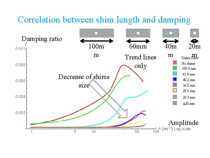
Correlation between shim length and damping Damping ratio 100 m m Decrease of shims size 60 mm Trend lines only 40 m m 20 m m Shims Sizes No shims 100. 0 mm 61. 9 mm 40. 2 mm 36. 0 mm 29. 9 mm 20. 3 mm φ20 mm Amplitude © Cranfield University
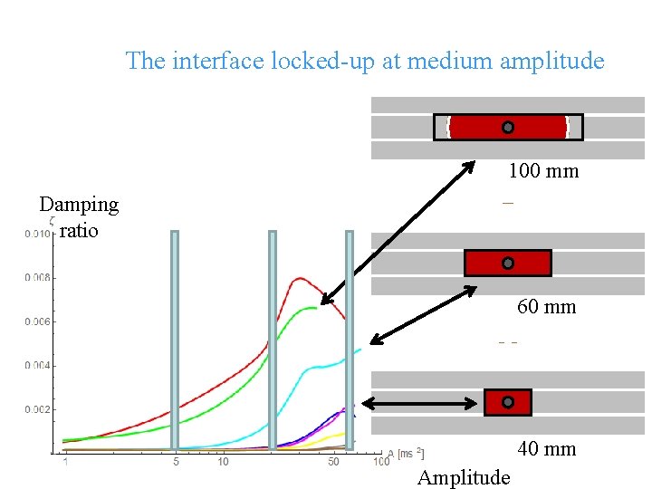
The interface locked-up at medium amplitude 100 mm Damping ratio 60 mm 40 mm © Cranfield University Amplitude
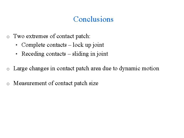
Conclusions o Two extremes of contact patch: • Complete contacts – lock up joint • Receding contacts – sliding in joint o Large changes in contact patch area due to dynamic motion o Measurement of contact patch size

www. cranfield. ac. uk T: +44 (0)1793 785810
- Slides: 29