INTROUCTION New Waltham is a flattened dumbbell 12

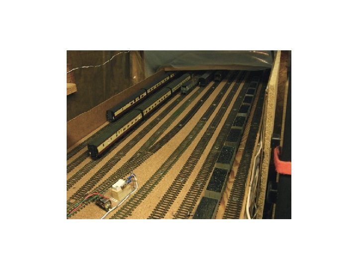
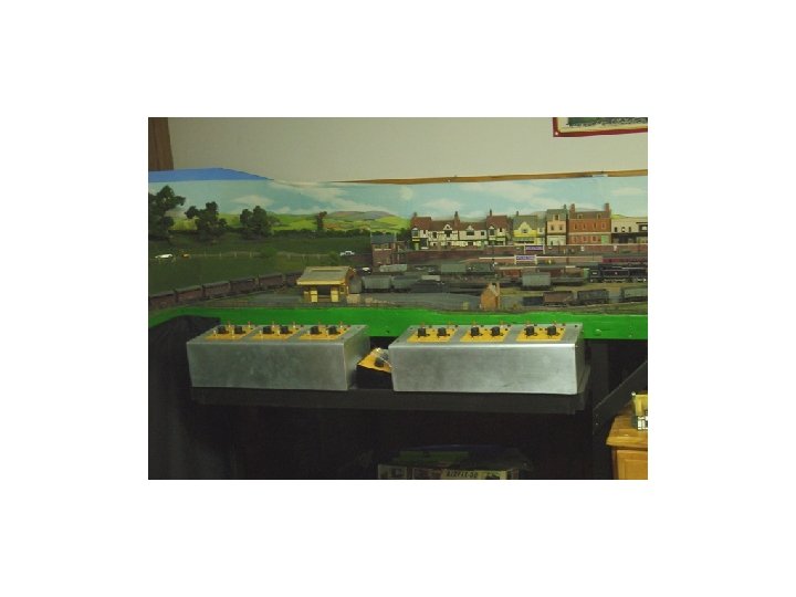
INTROUCTION New Waltham is a flattened dumbbell, 1/2 of which is scenic and 1/2 of which is hidden using traditional DC. When I started I decided I wanted to be able to sit and watch trains go by. This defined the layout as being a roundy round. However, I did not want a tail chaser and living where I do a multi operator layout was not going to happen. Accordingly I developed my automatic hidden siding system. This system lets me run 6 trains on the up line and 6 trains on the down line together in a fixed sequence at realistic speeds. Thus, express trains go by at speed and slow trains go by slowly. All this without any input from me. A complete cycle is about 14 minutes with gaps where there is nothing to see, just like the real thing. DESCRIPTON - Sidings There are six hidden sidings on each of the up and down lines, each with its own assigned train, e. g. an express passenger hauled by an A 4, an empty coal train hauled by a WD 2 -8 -0 or a stopping passenger train B 1 hauled. As an individual train enters its assigned siding, a small magnet attached to the underside of a vehicle close to the train end activates a reed switch mounted in the track as it passes over. The “pulse” generated by the reed switch is fed to the low voltage side of a cheap auto auxiliary equipment relay that fires a capacitor discharge unit to change the appropriate point motors and activate the train in the next track. All points are self isolating PECO so as the points are changed they automatically isolate the incoming train and power up the outgoing train. This process is repeated for each siding so that each train comes out of the hidden section into the scenic section and back into the hidden section to send out the next train. The hidden siding operation is not especially graceful since trains come to a sudden stop and immediately start at speed. At first I was a bit nervous that this instant on/off would damage the loco motors, but after about 8 years and many sessions, some of which have been over two continuous hours, there appears to be no negative impact. For the up line, where the hidden sidings are on a curve, the momentum caused by the instant off caused the rear coaches of a fast express to push those in front off the track. I used a simple resistor arrangement to mitigate the off effect. DESCRIPTION - Speed Control Each siding has its own speed controller that is always on and is pre-set to a speed appropriate for the train in the siding it controls. A common in two out micro switch (lever switch) is activated either by the point blade tie rod or the upper rod coming from the top of the Peco point motor. The micro switch is connected to a double pole double throw micro relay in the control box. Using what I call linear ladder logic, the appropriate power from the designated controller is fed to the track. Thus, just like the automatic siding operation, the train in activates the speed of the next train out.

I have installed an indicator light so that I know which controller is in use at any one time GENERAL Initially, I used a circuit from a hobby book that used things like silicon controlled rectifier circuits. This sort of worked, but was subject to stray currents and would activate a train at any time it chose. This resulted in some interesting conflicts and more than a bit of bad language. In the end I adopted the KISS system described here. Apart from burning one relay out when a magnet sat over the reed switch keeping it activated, the system has operated flawlessly for over 8 years now. The biggest single problem I had was learning about the operation of “traditional” reed switches. I had put the magnet at the back of the train so that as the train came to a stop there was sufficient momentum to take up the coupling slack and move the magnet past the reed switch. For express trains this worked perfectly, however for slow trains I would get the train sitting over the reed switch causing chatter stopping the automated sequencing process. Eventually, I discovered that the traditional reed switch has two “on” positions if placed longitudinally in the track. This is because the actual ferro magnetic iron is the contact on either side of the centre lever. Thus, as the magnet passes over there is one pulse as it hits the first wire of ferro magnetic iron, then after a short off a second on pulse again as it hits the second ferro magnetic wire. On a fast train there was enough momentum to propel the vehicle carrying the magnet past both contacts. On a slow train there was insufficient momentum. The solution was simple, stick the damm reed switch in from the side so that only one side is activated. As a matter of note I was able to purchase a number of home security reed switches that are used to monitor windows, etc. These are about 1/4” diameter and fit nicely between the track and do not have this double on situation. Also, for one pick-up freight that I run very slowly I found it necessary to put a small downhill “hump” after the reed switch to ensure that the vehicle with the magnet runs past the switch. At some point I may try to use the power from the activated track to push the train well clear of the reed switch and then stop it in an isolated section in front of the out point.

FUTURE Upgrade to 9 trains in each directions. This should give me a running time of 20+ minutes and more importantly will let me run all the must have locos they I continue to buy Install a station stop sequence for stopping passenger trains. I have a module and think I have a plan. TIP I have a RF panic switch that switches the power of to the main power bar. When I was setting all this up, somewhat surprisingly there were times when I got something wrong resulting in two or more trains heading out at the same time. After a while of sprinting from one room to another, banging my head as I ducted under the table and putting endless wagons back on the track when I wasn’t fast enough I can now stop everything at the press of a button from anywhere in the house. Technology is great.

Down Road Typical Track Loading Track 1, Express Passenger, A 4 hauled - Fast Track 2, Long Empty Coal Train, WD 2 -8 -0 hauled - Slow Track 3, Semi Fast Passenger Train, A 3 hauled - Intermediate fast Track 4, Iron Ore Train, 2 -10 -0 hauled - Slow Track 5, Stopping Passenger, B 1 hauled - Intermediate Track 6, Pick-up Freight, J 39 or O 4 hauled - Slow
 Motors 12 V DC Source Relay Track 1 Relay")
Low Voltage Side Point (Switch) Motors 12 V DC Source Relay Track 1 Relay Track 2 Relay Track 3 Common Reed Switch Track 1 Reed Switch Track 2 Reed Switch Track 3 Reed Switch Track 4 Reed Switch Track 5 Reed Switch Track 6 Notes: 1, Relays are cheap auto auxiliary fog/driving lamp relays 2, Green lines are low voltage low current relay input connections 3, Red lines are high voltage high amperage Capacitor Discharge Unit circuit Relay Track 4 Relay Track 5 Relay Track 6
 Motors Only one side of siding point motor connections")
Capacitor Discharge Side Point (Switch) Motors Only one side of siding point motor connections shown for simplicity 16 to 24 VAC IN Relay Track 1 Relay Track 2 Relay Track 3 Relay Track 4 Relay Track 5 Relay Track 6 Capacitor Discharge Unit Track 1 Track 2 Track 3 Track 4 Track 5 Common All point motors are self isolating Track 6 Point Motors. . Arrow indicates point throw (pull) direction Thus, CD unit pulls point tie bar in this direction To set points for straight ahead

Train Speed Control Circuit Train Siding Identifier Process 12 V Power Source in from master control unit Point Tie Rod (Bar) Return lines to controller selection relay array in master control unit Micro Switch or lever switch, as it is also known, Activated by point tie rod or point motor top pin

Track Train Control Unit set to desired speed for a specific train, e. g Slow for a goods Double pole micro relay 12 activation 24 V or greater on contacts Train Speed Control Unit One for each Siding On relay for individual controller activated by its specific microswitch Track 11 Track 1 Track 6 Controller Power source Input from microswitch for track 1 2 3 4 12 VDC Source 5 6 Common out to microswitch

Ladder Logic Circuit for Speed Control Relay Circuit Point tie bar Common In 1 2 3 4 5 6
 going from")
Siding Slow Down Section Train Direction Isolating Gap Simple Variable Resistor (Potensiometer) going from Zero to 10/20 Kohms For a slow freight train set resistor to 0. For a high speed express passenger train adjust resistor as appropriate so that the train slows down mitigating the impact of the sudden power loss as the points are switched. Reverse effect when power is abruptly switched on when the points are opened and starts up at a slower speed. I find this essential to avoid derailing a set of 10 close coupled coaches when using a curved storage siding
 travel 1 st contact 2")
Notes on Reed Switches Reed Switch Direction of (magnet) travel 1 st contact 2 nd contact Wrong! On a slow moving train this will give two pulses Moving Contact Correct, only gives a single pulse Ferro magnetic iron (Tricky to solder to) For slow moving trains, where there is minimum momentum to propel the wagons past the reed switch effective magnetic field area, I have put a small hump - about 1/16” high - to ensure the wagon with the magnet rolls clear Loco motion lost At this point as wagon passes over reed switch Wagons roll down hill taking up coupling slack and clear magnetic field area when loco stops Reed Switch Track Direction of travel
- Slides: 13