
Introduction to VHDL Spring 09 1 What is

- Slides: 40
Introduction to VHDL Spring 09 1
What is VHDL? • VHDL can be uses to model and synthesise digital systems. • VHDL = VHSIC Hardware Description Language – VHSIC = Very High Speed Integrated Circuit • Developed in early 1980’s by DOD. • Veralog is an older hardware description language. – Some (for example ASIC designers) prefer Veralog. • ANSI/IEEE Std 1076 -1993 is the version we will use. – ANSI/IEEE Std 1076 -2002 is the newest version. • VHDL is a very complex language. • VHDL descriptions can be synthesized and implemented in programmable logic. – Synthesis tools can accept a only subset of VHDL. 2
VHDL • Primarily for modeling digital systems. – Lesser extent analog • Reasons for modeling – Specify requirements – Simulation, testing, verification – Synthesis • Advantage – – • Increase reliability Minimize cost and design time Increase flexibility and ease with which a system can be modified. Avoid design errors through use of simulation. Problem – We model our conception of the system. – May not accurately reflect reality. 3
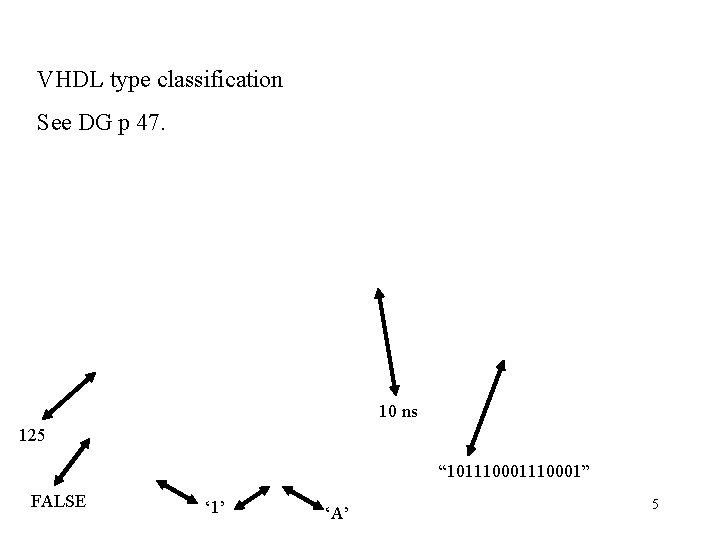
Types • The concept of type is important and fundamental when describing data in VHDL. • The type of a data object defines the set of values that an object can assume, as well as the set of operations that can be performed on those values. – For example data object of type bit can assume a value of either ‘ 0’ or ‘ 1’, and can support operators such as “and”, “or”, “xor”, “nand”, etc. • VHDL is a strongly typed language. • Scalar data types consists of single, indivisible values. • Besides the usual types such as integer and real, VHDL also provides other types such as time and bit. • User defined types are frequently employed. • We will make extensive use of standard libraries that define special types such as stdlogic. – We will use stdlogic in place of bit. Stdlogic can assume more values that 0 and 1. For example high impedance and don’t care values. 4
VHDL type classification See DG p 47. 10 ns 125 “ 101110001” FALSE ‘ 1’ ‘A’ 5
Operations that can be performed on type integer. See p 35 6
Operations on type Boolean and type Bit. See p 44 7
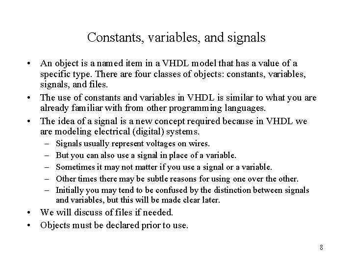
Constants, variables, and signals • An object is a named item in a VHDL model that has a value of a specific type. There are four classes of objects: constants, variables, signals, and files. • The use of constants and variables in VHDL is similar to what you are already familiar with from other programming languages. • The idea of a signal is a new concept required because in VHDL we are modeling electrical (digital) systems. – – – Signals usually represent voltages on wires. But you can also use a signal in place of a variable. Sometimes it may not matter if you use a signal or a variable. Other times there may be subtle reasons for using one over the other. Initially you may tend to be confused by the distinction between signals and variables, but this will be made clear later. • We will discuss of files if needed. • Objects must be declared prior to use. 8
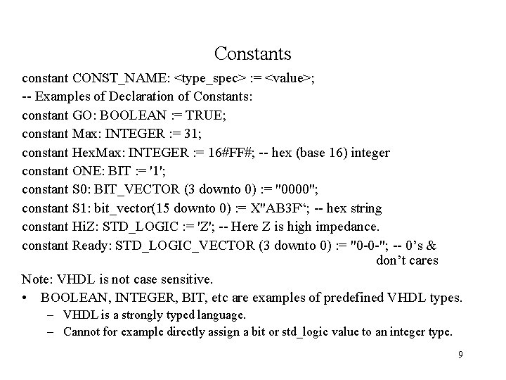
Constants constant CONST_NAME: <type_spec> : = <value>; -- Examples of Declaration of Constants: constant GO: BOOLEAN : = TRUE; constant Max: INTEGER : = 31; constant Hex. Max: INTEGER : = 16#FF#; -- hex (base 16) integer constant ONE: BIT : = '1'; constant S 0: BIT_VECTOR (3 downto 0) : = "0000"; constant S 1: bit_vector(15 downto 0) : = X"AB 3 F“; -- hex string constant Hi. Z: STD_LOGIC : = 'Z'; -- Here Z is high impedance. constant Ready: STD_LOGIC_VECTOR (3 downto 0) : = "0 -0 -"; -- 0’s & don’t cares Note: VHDL is not case sensitive. • BOOLEAN, INTEGER, BIT, etc are examples of predefined VHDL types. – VHDL is a strongly typed language. – Cannot for example directly assign a bit or std_logic value to an integer type. 9
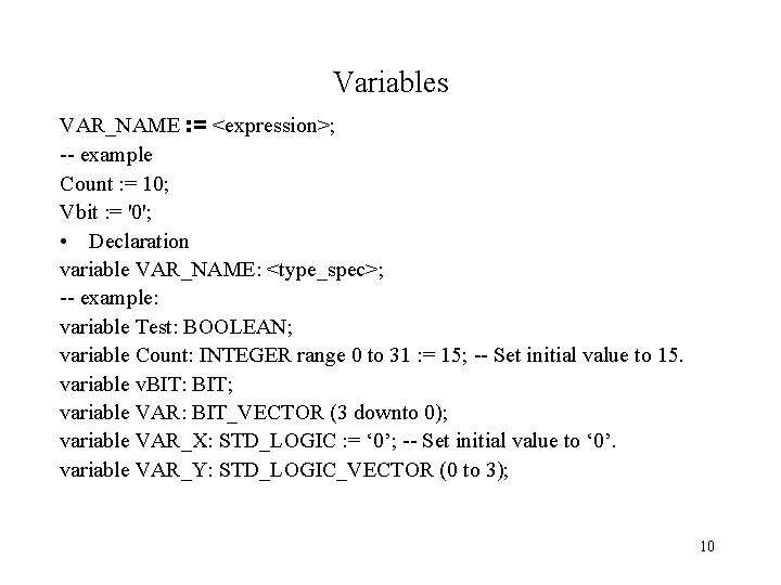
Variables VAR_NAME : = <expression>; -- example Count : = 10; Vbit : = '0'; • Declaration variable VAR_NAME: <type_spec>; -- example: variable Test: BOOLEAN; variable Count: INTEGER range 0 to 31 : = 15; -- Set initial value to 15. variable v. BIT: BIT; variable VAR: BIT_VECTOR (3 downto 0); variable VAR_X: STD_LOGIC : = ‘ 0’; -- Set initial value to ‘ 0’. variable VAR_Y: STD_LOGIC_VECTOR (0 to 3); 10
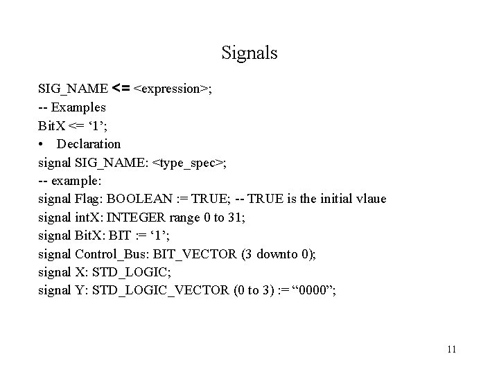
Signals SIG_NAME <= <expression>; -- Examples Bit. X <= ‘ 1’; • Declaration signal SIG_NAME: <type_spec>; -- example: signal Flag: BOOLEAN : = TRUE; -- TRUE is the initial vlaue signal int. X: INTEGER range 0 to 31; signal Bit. X: BIT : = ‘ 1’; signal Control_Bus: BIT_VECTOR (3 downto 0); signal X: STD_LOGIC; signal Y: STD_LOGIC_VECTOR (0 to 3) : = “ 0000”; 11
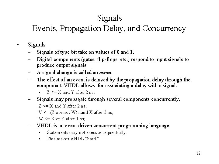
Signals Events, Propagation Delay, and Concurrency • Signals – – Signals of type bit take on values of 0 and 1. Digital components (gates, flip-flops, etc. ) respond to input signals to produce output signals. A signal change is called an event. The effect of an event is delayed by the propagation delay through the component. VHDL allows for associating a delay with a signal. • – Z <= X and Y after 2 ns; Signals may propagate through several components concurrently. Z <= X and Y after 2 ns; V <= (Z xor not W) nand X after 3 ns; W <= X or Y after 1 ns; – VHDL is an event driven concurrent programming language. • • Statements may not execute sequentially. This makes VHDL “hard. ” 12
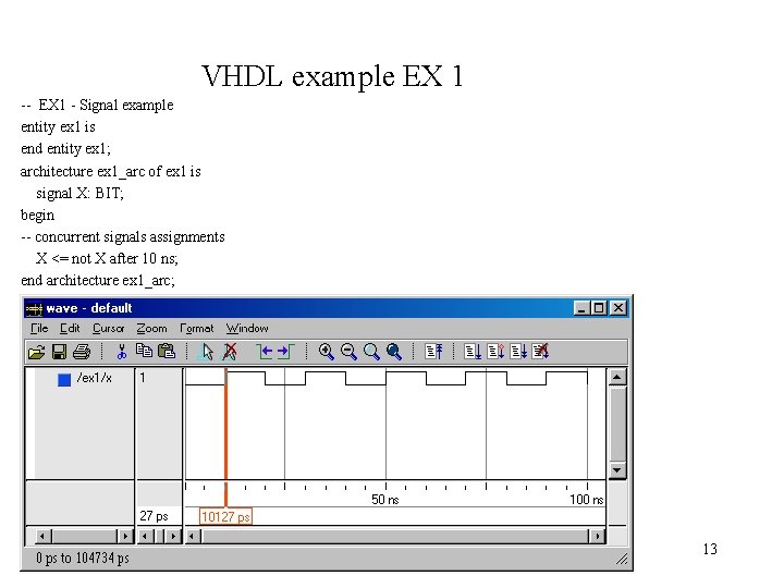
VHDL example EX 1 -- EX 1 - Signal example entity ex 1 is end entity ex 1; architecture ex 1_arc of ex 1 is signal X: BIT; begin -- concurrent signals assignments X <= not X after 10 ns; end architecture ex 1_arc; 13
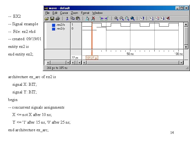
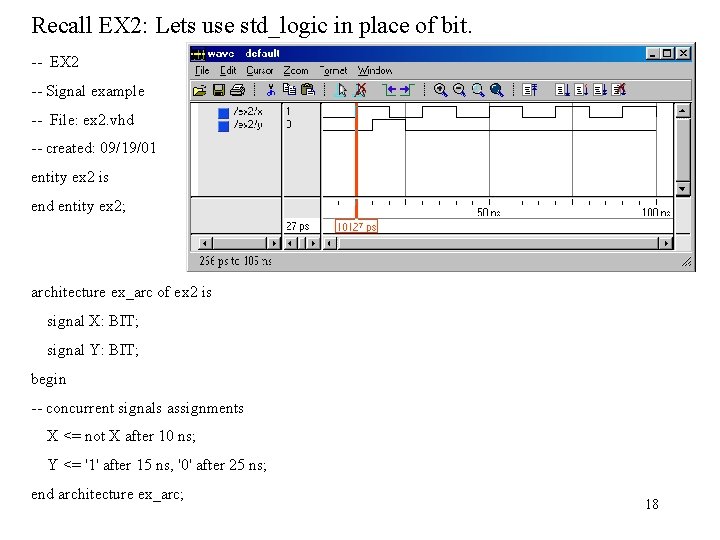
-- EX 2 -- Signal example -- File: ex 2. vhd -- created: 09/19/01 entity ex 2 is end entity ex 2; architecture ex_arc of ex 2 is signal X: BIT; signal Y: BIT; begin -- concurrent signals assignments X <= not X after 10 ns; Y <= '1' after 15 ns, '0' after 25 ns; end architecture ex_arc; 14
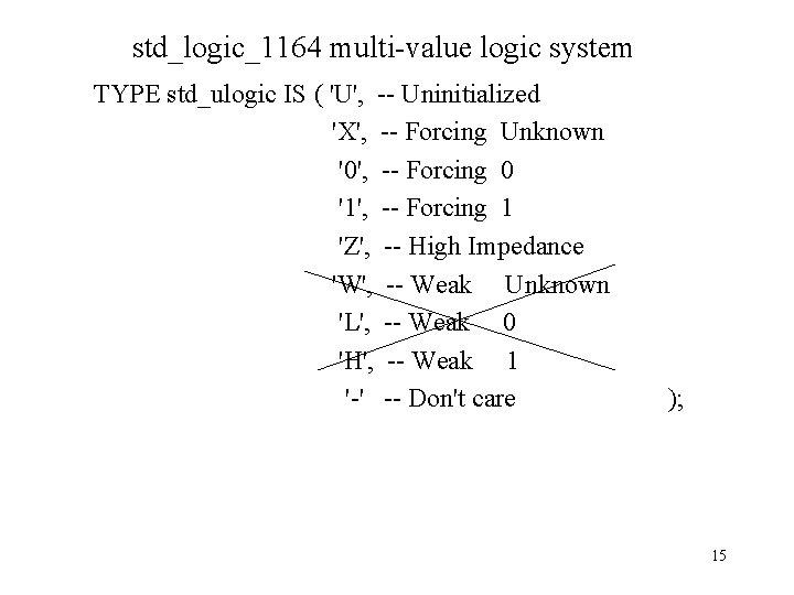
std_logic_1164 multi-value logic system TYPE std_ulogic IS ( 'U', -- Uninitialized 'X', -- Forcing Unknown '0', -- Forcing 0 '1', -- Forcing 1 'Z', -- High Impedance 'W', -- Weak Unknown 'L', -- Weak 0 'H', -- Weak 1 '-' -- Don't care ); 15
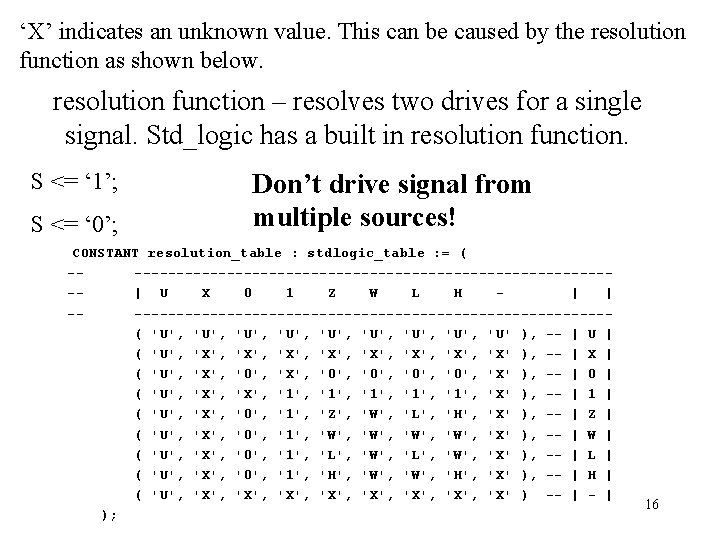
‘X’ indicates an unknown value. This can be caused by the resolution function as shown below. resolution function – resolves two drives for a single signal. Std_logic has a built in resolution function. S <= ‘ 1’; S <= ‘ 0’; Don’t drive signal from multiple sources! CONSTANT resolution_table : stdlogic_table : = ( -----------------------------| U X 0 1 Z W L H | | -----------------------------( 'U', 'U', 'U' ), -- | U | ( 'U', 'X', 'X', 'X' ), -- | X | ( 'U', 'X', '0', '0', 'X' ), -- | 0 | ( 'U', 'X', '1', '1', 'X' ), -- | 1 | ( 'U', 'X', '0', '1', 'Z', 'W', 'L', 'H', 'X' ), -- | Z | ( 'U', 'X', '0', '1', 'W', 'X' ), -- | W | ( 'U', 'X', '0', '1', 'L', 'W', 'X' ), -- | L | ( 'U', 'X', '0', '1', 'H', 'W', 'H', 'X' ), -- | H | ( 'U', 'X', 'X', 'X' ) -- | ); 16
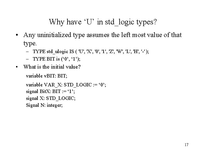
Why have ‘U’ in std_logic types? • Any uninitialized type assumes the left most value of that type. – TYPE std_ulogic IS ( 'U', 'X', '0', '1', 'Z', 'W', 'L', 'H', '-' ); – TYPE BIT is (‘ 0’, ‘ 1’); • What is the initial value? variable v. BIT: BIT; variable VAR_X: STD_LOGIC : = ‘ 0’; signal Bit. X: BIT : = ‘ 1’; signal X: STD_LOGIC; Signal N: integer; 17
Recall EX 2: Lets use std_logic in place of bit. -- EX 2 -- Signal example -- File: ex 2. vhd -- created: 09/19/01 entity ex 2 is end entity ex 2; architecture ex_arc of ex 2 is signal X: BIT; signal Y: BIT; begin -- concurrent signals assignments X <= not X after 10 ns; Y <= '1' after 15 ns, '0' after 25 ns; end architecture ex_arc; 18
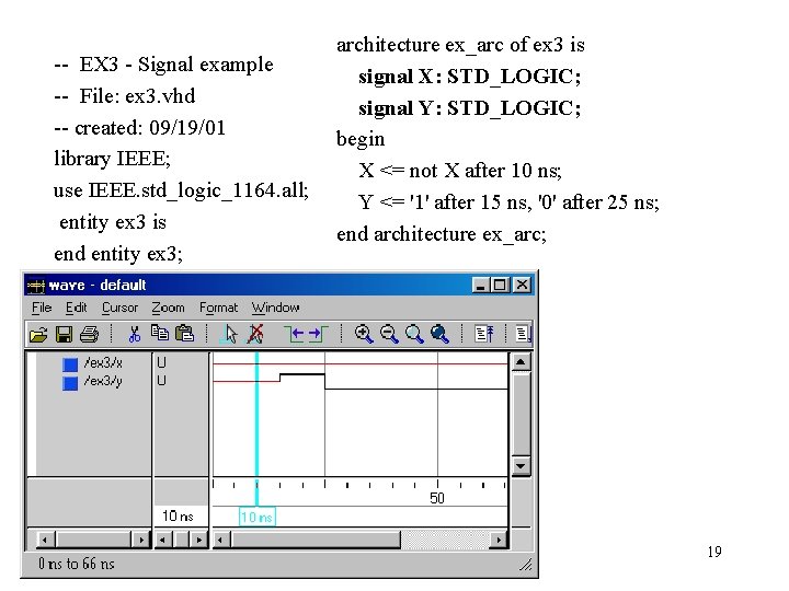
-- EX 3 - Signal example -- File: ex 3. vhd -- created: 09/19/01 library IEEE; use IEEE. std_logic_1164. all; entity ex 3 is end entity ex 3; architecture ex_arc of ex 3 is signal X: STD_LOGIC; signal Y: STD_LOGIC; begin X <= not X after 10 ns; Y <= '1' after 15 ns, '0' after 25 ns; end architecture ex_arc; 19
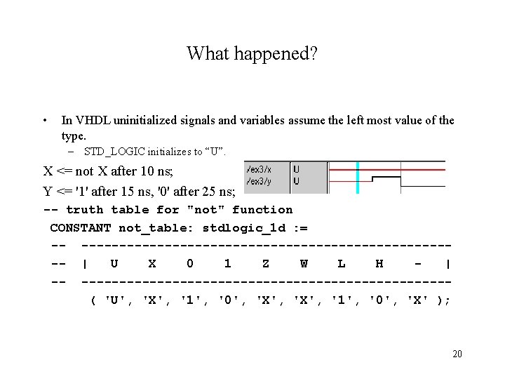
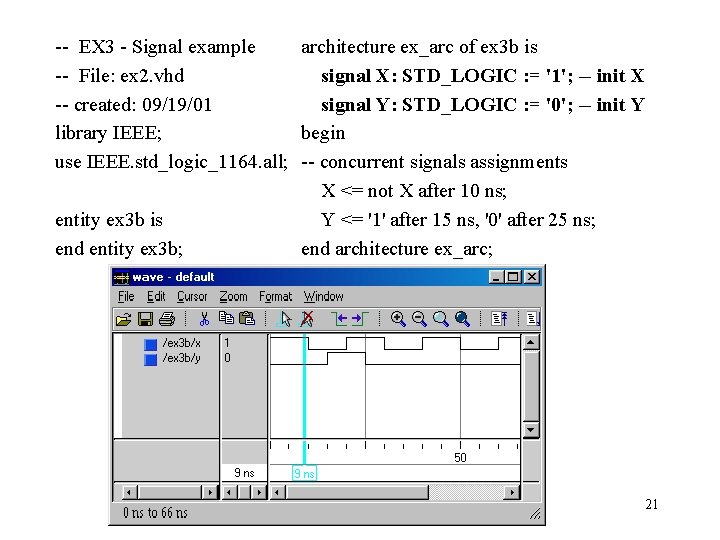
What happened? • In VHDL uninitialized signals and variables assume the left most value of the type. – STD_LOGIC initializes to “U”. X <= not X after 10 ns; Y <= '1' after 15 ns, '0' after 25 ns; -- truth table for "not" function CONSTANT not_table: stdlogic_1 d : = -- ------------------------- | U X 0 1 Z W L H | -- ------------------------( 'U', 'X', '1', '0', 'X' ); 20
-- EX 3 - Signal example architecture ex_arc of ex 3 b is -- File: ex 2. vhd signal X: STD_LOGIC : = '1'; -- init X -- created: 09/19/01 signal Y: STD_LOGIC : = '0'; -- init Y library IEEE; begin use IEEE. std_logic_1164. all; -- concurrent signals assignments X <= not X after 10 ns; entity ex 3 b is Y <= '1' after 15 ns, '0' after 25 ns; end entity ex 3 b; end architecture ex_arc; 21
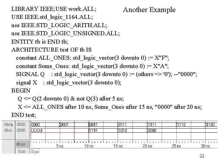
LIBRARY IEEE; USE work. ALL; Another Example USE IEEE. std_logic_1164. ALL; use IEEE. STD_LOGIC_ARITH. ALL; use IEEE. STD_LOGIC_UNSIGNED. ALL; ENTITY tb is END tb; ARCHITECTURE test OF tb IS constant ALL_ONES: std_logic_vector(3 downto 0) : = X"F"; constant Some_Ones: std_logic_vector(3 downto 0) : = X"A"; SIGNAL Q : std_logic_vector(3 downto 0) : = (others => '0'); --"0000"; signal X : std_logic_vector(3 downto 0); BEGIN Q <= Q(2 downto 0) & not Q(3) after 5 ns; X <= ALL_ONES after 10 ns, Some_Ones after 15 ns, "0000" after 20 ns; END test; 22
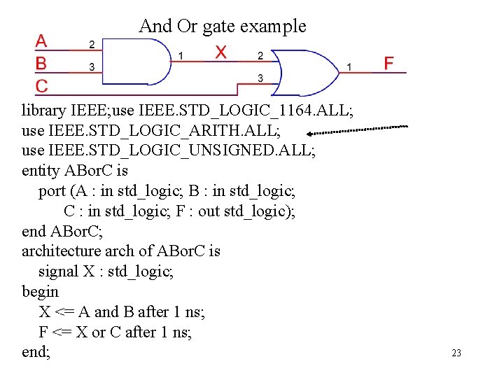
And Or gate example library IEEE; use IEEE. STD_LOGIC_1164. ALL; use IEEE. STD_LOGIC_ARITH. ALL; use IEEE. STD_LOGIC_UNSIGNED. ALL; entity ABor. C is port (A : in std_logic; B : in std_logic; C : in std_logic; F : out std_logic); end ABor. C; architecture arch of ABor. C is signal X : std_logic; begin X <= A and B after 1 ns; F <= X or C after 1 ns; end; 23
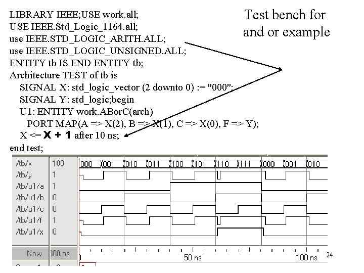
LIBRARY IEEE; USE work. all; Test bench for USE IEEE. Std_Logic_1164. all; and or example use IEEE. STD_LOGIC_ARITH. ALL; use IEEE. STD_LOGIC_UNSIGNED. ALL; ENTITY tb IS END ENTITY tb; Architecture TEST of tb is SIGNAL X: std_logic_vector (2 downto 0) : = "000"; SIGNAL Y: std_logic; begin U 1: ENTITY work. ABor. C(arch) PORT MAP(A => X(2), B => X(1), C => X(0), F => Y); X <= X + 1 after 10 ns; end test; 24
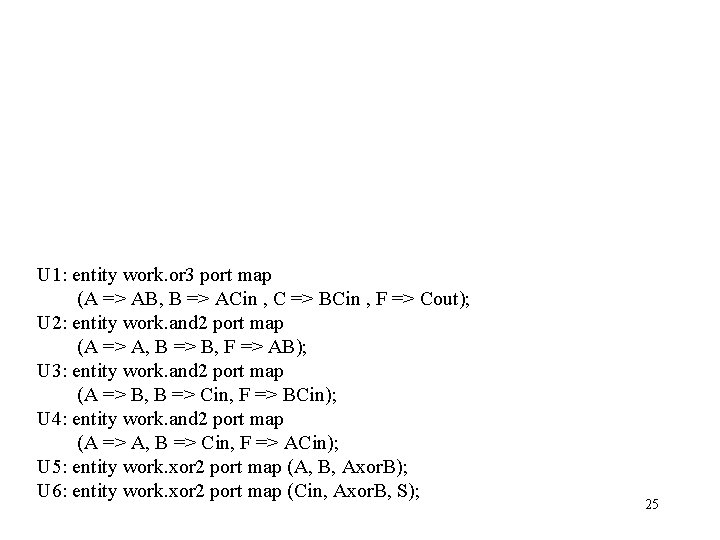
U 1: entity work. or 3 port map (A => AB, B => ACin , C => BCin , F => Cout); U 2: entity work. and 2 port map (A => A, B => B, F => AB); U 3: entity work. and 2 port map (A => B, B => Cin, F => BCin); U 4: entity work. and 2 port map (A => A, B => Cin, F => ACin); U 5: entity work. xor 2 port map (A, B, Axor. B); U 6: entity work. xor 2 port map (Cin, Axor. B, S); 25
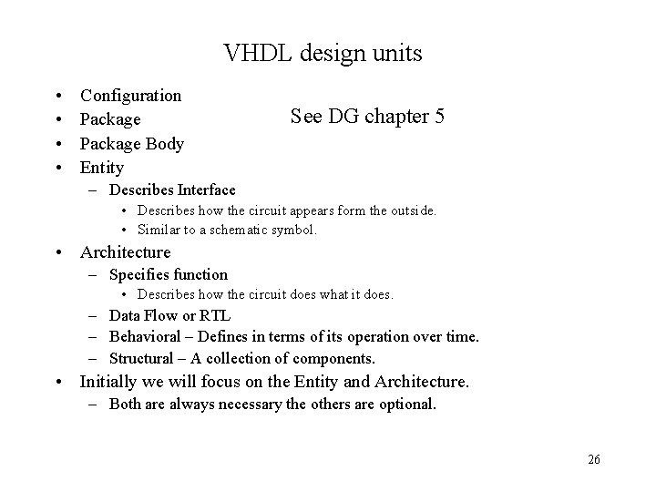
VHDL design units • • Configuration Package Body Entity See DG chapter 5 – Describes Interface • Describes how the circuit appears form the outside. • Similar to a schematic symbol. • Architecture – Specifies function • Describes how the circuit does what it does. – Data Flow or RTL – Behavioral – Defines in terms of its operation over time. – Structural – A collection of components. • Initially we will focus on the Entity and Architecture. – Both are always necessary the others are optional. 26
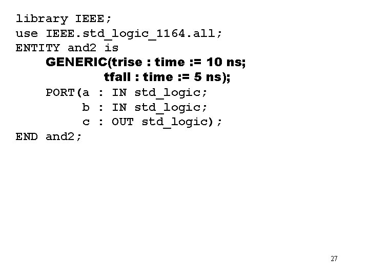
library IEEE; use IEEE. std_logic_1164. all; ENTITY and 2 is GENERIC(trise : time : = 10 ns; tfall : time : = 5 ns); PORT(a : IN std_logic; b : IN std_logic; c : OUT std_logic); END and 2; 27
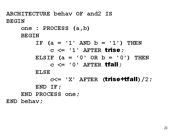
ARCHITECTURE behav OF and 2 IS BEGIN one : PROCESS (a, b) BEGIN IF (a = '1' AND b = '1') THEN c <= '1' AFTER trise; ELSIF (a = '0' OR b = '0') THEN c <= '0' AFTER tfall; ELSE c<= 'X' AFTER (trise+tfall)/2; END IF; END PROCESS one; END behav; 28
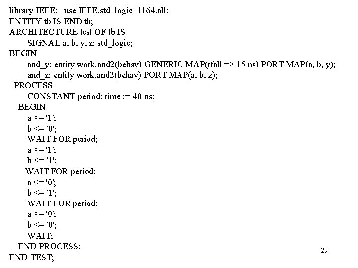
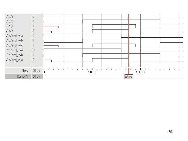
library IEEE; use IEEE. std_logic_1164. all; ENTITY tb IS END tb; ARCHITECTURE test OF tb IS SIGNAL a, b, y, z: std_logic; BEGIN and_y: entity work. and 2(behav) GENERIC MAP(tfall => 15 ns) PORT MAP(a, b, y); and_z: entity work. and 2(behav) PORT MAP(a, b, z); PROCESS CONSTANT period: time : = 40 ns; BEGIN a <= '1'; b <= '0'; WAIT FOR period; a <= '1'; b <= '1'; WAIT FOR period; a <= '0'; b <= '0'; WAIT; END PROCESS; 29 END TEST;
30
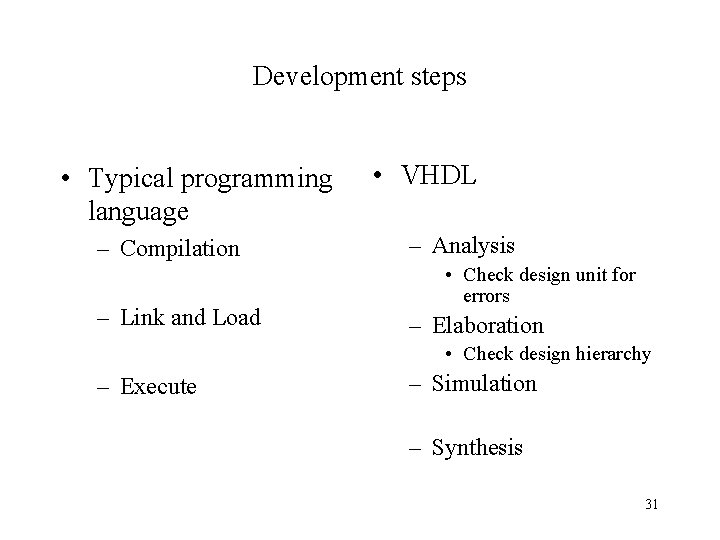
Development steps • Typical programming language – Compilation – Link and Load • VHDL – Analysis • Check design unit for errors – Elaboration • Check design hierarchy – Execute – Simulation – Synthesis 31
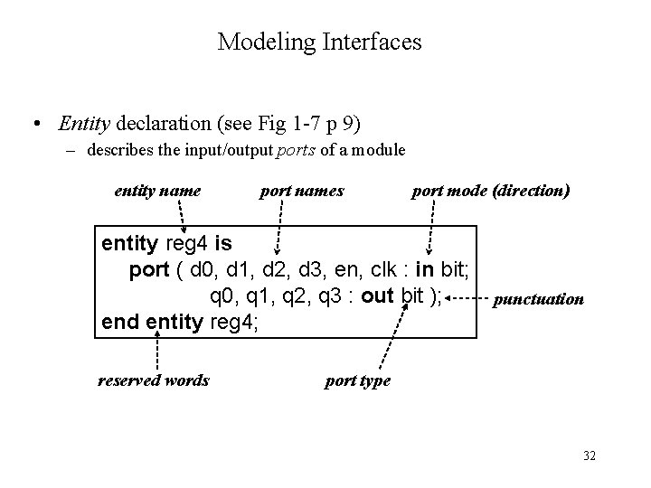
Modeling Interfaces • Entity declaration (see Fig 1 -7 p 9) – describes the input/output ports of a module entity name port names port mode (direction) entity reg 4 is port ( d 0, d 1, d 2, d 3, en, clk : in bit; q 0, q 1, q 2, q 3 : out bit ); end entity reg 4; reserved words punctuation port type 32
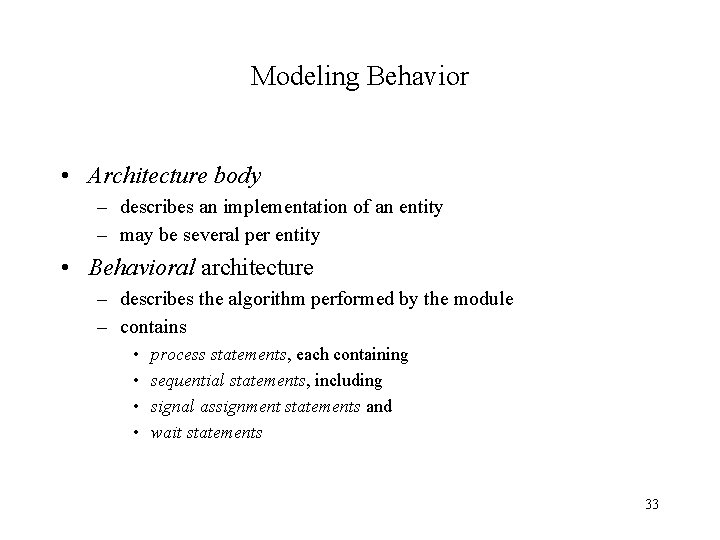
Modeling Behavior • Architecture body – describes an implementation of an entity – may be several per entity • Behavioral architecture – describes the algorithm performed by the module – contains • • process statements, each containing sequential statements, including signal assignment statements and wait statements 33
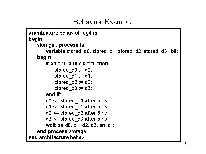
Behavior Example architecture behav of reg 4 is begin storage : process is variable stored_d 0, stored_d 1, stored_d 2, stored_d 3 : bit; begin if en = '1' and clk = '1' then stored_d 0 : = d 0; stored_d 1 : = d 1; stored_d 2 : = d 2; stored_d 3 : = d 3; end if; q 0 <= stored_d 0 after 5 ns; q 1 <= stored_d 1 after 5 ns; q 2 <= stored_d 2 after 5 ns; q 3 <= stored_d 3 after 5 ns; wait on d 0, d 1, d 2, d 3, en, clk; end process storage; end architecture behav; 34
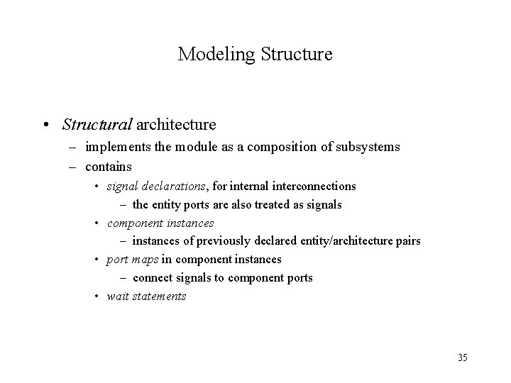
Modeling Structure • Structural architecture – implements the module as a composition of subsystems – contains • signal declarations, for internal interconnections – the entity ports are also treated as signals • component instances – instances of previously declared entity/architecture pairs • port maps in component instances – connect signals to component ports • wait statements 35
Structure Example 36
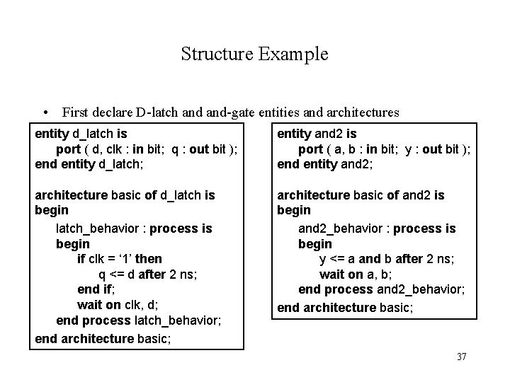
Structure Example • First declare D-latch and-gate entities and architectures entity d_latch is port ( d, clk : in bit; q : out bit ); end entity d_latch; entity and 2 is port ( a, b : in bit; y : out bit ); end entity and 2; architecture basic of d_latch is begin latch_behavior : process is begin if clk = ‘ 1’ then q <= d after 2 ns; end if; wait on clk, d; end process latch_behavior; end architecture basic; architecture basic of and 2 is begin and 2_behavior : process is begin y <= a and b after 2 ns; wait on a, b; end process and 2_behavior; end architecture basic; 37
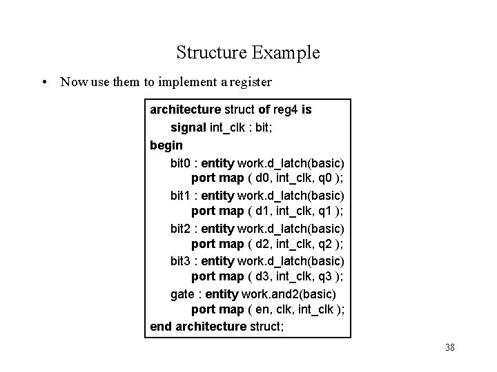
Structure Example • Now use them to implement a register architecture struct of reg 4 is signal int_clk : bit; begin bit 0 : entity work. d_latch(basic) port map ( d 0, int_clk, q 0 ); bit 1 : entity work. d_latch(basic) port map ( d 1, int_clk, q 1 ); bit 2 : entity work. d_latch(basic) port map ( d 2, int_clk, q 2 ); bit 3 : entity work. d_latch(basic) port map ( d 3, int_clk, q 3 ); gate : entity work. and 2(basic) port map ( en, clk, int_clk ); end architecture struct; 38
VHDL Reserved Words 39
40