Introduction to Verification Concepts Ayas Kanta Swain Assistant


- Slides: 23
Introduction to Verification Concepts Ayas Kanta Swain, Assistant Professor, ECE Dept. , NIT Rourkela
Introduction o How you plan to verify your particular design ? o how this influences the test bench structure. ? o Ex-Just as all houses have kitchens, bedrooms, and bathrooms, ü all test benches share some common structure of stimulus generation and response checking. Important principle: as a verification engineer is: ü “Bugs are good. ” ü Don’t shy away from finding the next bug, ü Keep track of the details of each bug found. ü Each bug found before tape-out is one fewer that ends up in the customer’s hands. ü At each stage in the design the cost of fixing a bug goes up by a factor of 10, so find those bugs early and often.
The Verification Process • • • What is the goal of verification? “Finding bugs, ” (partly correct). Bugs are discrepancy between specification and the actual design. The process of verification parallels the design creation process. Ø Hardware designer creates a device that performs a particular task ü Reads the hardware specification for a block, ü Interprets the human language description, ü Creates the corresponding logic in a machine-readable form, usually RTL code. Ø Ambiguities in the original document, missing details, or conflicting descriptions. Ø Verification engineer is to make sure the device can accomplish that task successfully. ü must also read the hardware specification, create the verification plan, and ü follow it to build tests showing ü the RTL code correctly implements the features. Ø The design is an accurate representation of the specification.
What is Verification Process of demonstrating functional correctness of a design. ü to understand the design and its intent, ü to consider all the corner test cases that the designer might not have thought about. ü to read the same hardware specifications and make an independent assessment of what they mean. ü Exercise the RTL to show that it matches your interpretation.
Importance of Verification What if design is not pass through verification? ü Incorrect/Insufficient Specifications ü Misinterpretation and Misunderstandings ü Incorrect interaction between IPs/Cores ü Unexpected behavior of the system Importance of Verification ü Bug escapes to silicon can be costly including re-spin ü 70 % of design cycles is spent in verifying design ü Ever increasing complexity of designs makes this harder ü Hence Verification is always on critical path for any product design
Testing at Different Levels Each level of Verification will be suited for a specific objective: Lower levelsü need to create tests that generate stimuli from all the surrounding blocks ü have better controllability and visibility ü Faster Block levelü Verification helps designs to be verified independently and in parallel System Level. Verification focuses more on interactions and integration phase. ü the entire system is tested, ü but the simulation performance is greatly reduced. Example - ATM
The Verification Plan and Approaches Ø The verification plan is derived from the hardware specification documents ü Contains a description of what features need to be exercised under what conditions. ü Techniques to be used: Directed or random testing, assertions, HW/SW co-verification, Emulation, formal proofs, and use of verification IP. Ø White Box ü Intimate knowledge of design implementation ü Full visibility and observability
Basic Test bench Functionality The purpose of a test bench is to determine the correctness of the DUT. This is accomplished by the following steps. ü Generate stimulus ü Apply stimulus to the DUT ü Capture the response ü Check for correctness ü Measure progress against the overall verification goals Ø Some steps are accomplished automatically by the test bench, while others are manually determined by you.
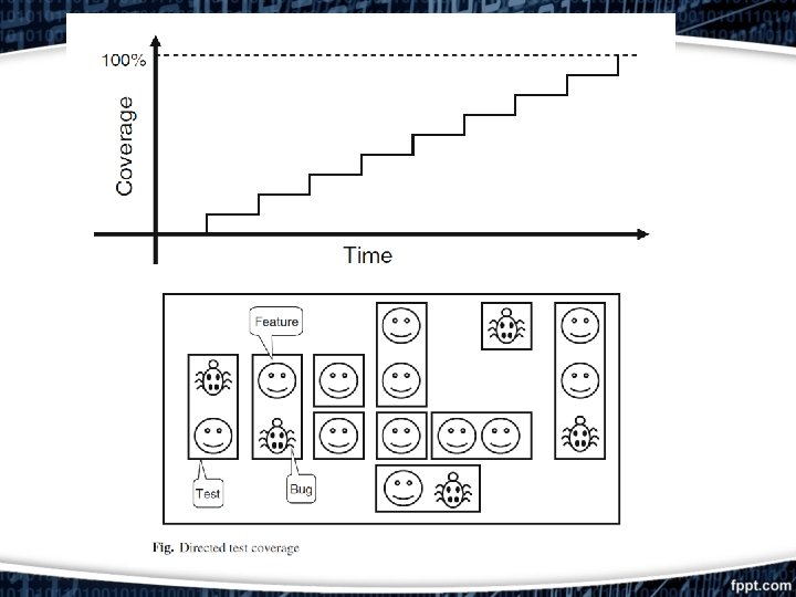
Directed Testing In directed tests approach, ü look at the hardware specification, ü write a verification plan with a list of tests, (each of which concentrated on a set of related features). ü With this plan, you write stimulus vectors that exercise these features in the DUT. ü Simulate the DUT with these vectors ü Manually review the resulting log files and waveforms to make sure the design does what you expect. Ø Once the test works correctly, you check it off in the verification plan and move to the next one. Ø Given ample time and staffing, directed testing is sufficient to verify many designs.
Directed Testing • What if you do not have the necessary time or resources to carry out the directed testing approach? • Forward progress comes the slope remains the same. • If the design complexity doubles, it takes twice as long to complete or requires twice as many people to implement it. • Example: To verify every combination of inputs for a 32 -bit adder, simulations would still be running years after the project should have shipped.
Random Testing • Random stimulus is crucial for exercising complex designs. • A directed test finds the bugs you expect to be in the design, whereas a random test can find bugs you never anticipated. • Random stimuli needs functional coverage to measure verification progress. • Furthermore, need an automated way to predict the results — generally a scoreboard or reference model. • A layered testbench helps you control the complexity by breaking the problem into manageable pieces. • Transactors provide a useful pattern for building these pieces. • With appropriate planning, a common test bench infrastructure can be shared by all tests and does not have to be continually modified.
• Every random test shares common test bench, as opposed to directed tests where each is written from scratch. • Constrained-random test bench is now finding bugs faster than the many directed ones. • The last few bugs may only be found with directed tests, but the vast majority of bugs will be found with random tests. A random test bench can always turned into directed tests. Directed Test bench can never be turned into a true random test bench.
Constrained-Random Stimulus
Coverage • What is Coverage? – Coverage is the metric of completeness of verification. • Why coverage? – Verification is based on samples • Need to know that all areas of the design have been verified • Functional Coverage and Code Coverage • Functional Coverage -Covers the functionality of the DUT • Code Coverage- Covers all the statements, branch operation, conditional statements, toggling of inputs, State Coverage. 15
Test bench Components In simulation, the test bench wraps around the DUT, just as a hardware tester connects to a physical chip. ü It is comprised of many Bus Functional Models (BFM) ü They look like real components, but they are part of the testbench, not the RTL design. ü Build equivalent components in your testbench that can generate stimulus and check the response, ü These are not detailed, synthesizable models, ü High level transactors that obey the protocol, and execute more quickly.
Layered Testbench Components It divides the code into smaller pieces that can be developed separately. Signal layer: ü It contains the design under test and the signals that connect it to the test bench. Command layer: ü The DUT’s inputs are driven by the driver that runs single commands, such as bus read or write. ü The DUT’s output drives the monitor that takes signal transitions and groups them together into commands. ü Assertions looks at individual signals and also changes across an entire command.
Layered Testbench Components The Functional Layer: ü The functional layer feeds down into the command layer. ü The agent block (called the transactor) receives higher-level transactions such as DMA read or write and breaks them into individual commands or transactions. ü These commands are also sent to the scoreboard that predicts the results of the transaction. ü The checker compares the commands from the monitor with those in the scoreboard.
The Scenario Layer The functional layer is driven by the generator in the scenario layer, as shown in Figure Scenario? Helps to make sure that this device accomplishes its intended task. MP 3 player concurrently play music from its storage, download new music respond to input from the user (adjusting the volume and track controls). Each of these operations is a scenario. Ø Downloading a music file takes several steps, such as control register reads and writes to set up the operation, multiple DMA writes to transfer the song, and then another group of reads and writes such as track size and memory location.
The Test Layer and Functional Coverage Test layer: Top of the testbench. • The test contains the constraints to create the stimulus. • Functional coverage measures the progress of all tests in fulfilling the verification plan requirements. • The functional coverage code changes through the project as the various criteria complete. (As modified this layer is not part of the environment). • in the Creating a Simple Driver
Summary of Verification Methodology Modern day verification methodology has the following features: ü Constrained-random stimulus ü Functional coverage ü Layered testbench using transactors ü Common testbench for all tests ü Test case-specific code kept separate from testbench
References • Chris Spear, “System Verilog for Verification: A Guide to Learning the Testbench Language Features”, Springer US, 2008 • Verificationexcellence. Usefedora. com • Chipverify. com • https: //www. verificationguide. com/p/systemverilog-tutorial. html • http: //www. asic-world. com/systemverilog/tutorial. html • http: //www. testbench. in/SV_00_INDEX. html