Introduction to Tiefenbach Wheel Sensor Technology A guide

Introduction to Tiefenbach Wheel Sensor Technology A guide to installing Tiefenbach Wheel Sensors

Advantages of Axle Counting • Immunity to poor ballast and track conditions • Immunity to electromagnetic interference • Resistant to lightning damage • Not affected by magnetic brakes, etc. • No insulated joints • No bonds, chicken heads, etc. • Incredible reliability

The Double Wheel Sensor “DSS” The “heart” of the Axle Counter System

DSS Characteristics • An active device – requires DC power from system rack • Wheel passing over device decreases losses in magnetic field • Loading changes, resulting in voltage increase shunting circuit • Pulse width (duration) and amplitude analyzed and processed by input-amplifier card for control functions
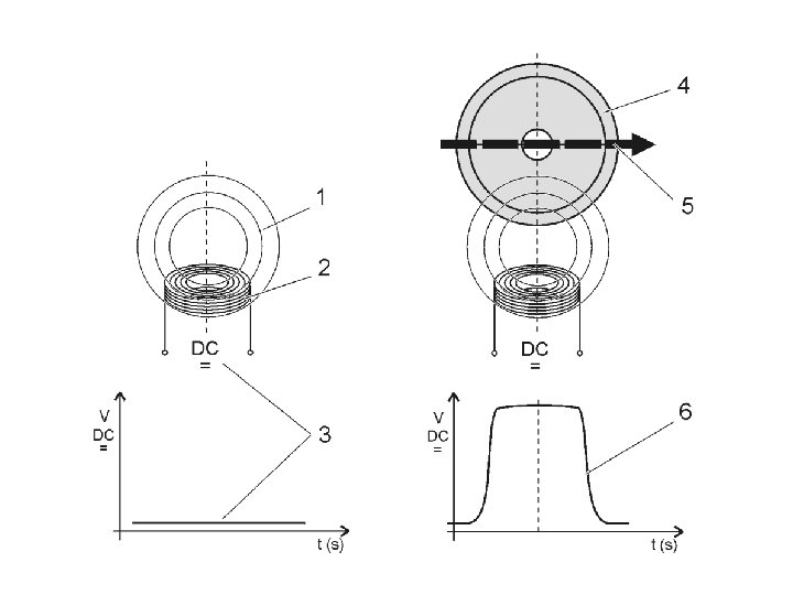

The sensor is set to operate within a specific detection distance Detection distance is adjustable Pulses must overlap for proper detection Sequence and pulse duration can be used to identify direction and speed of movement

Internal System One Brown / Yellow Pair DSS Details Internal System Two Green/White Pair • Two galvanically separate sensors in one package • Allow direction and speed calculations (CWT System)

System One DSS Details Reduction Plate, held to rail using brass ferrules (not used with 200 - series sensor!) 13 -mm “tight-fit” bolts System Two Spacer (shim) always on back side of reduction plate next web of rail Depends on rail profile (size/type) refer to installation manual

DSS Details System One Electrical Switching Height Adjustment System Two White cap for securing and protecting slug assembly

The EW-1 Alignment Tool Right-angle drive AKA – “The Dental Drill” Push up Maintainer removes retaining nut, inserts EW-1, and pushes-up to engage slug Important! Failure to push up with the EW-1 alignment tool to unlock the adjustment mechanism can result in damage to the sensor

DSS Failsafe Functions • Detected at Input-Amplifier Card • Detects off-rail condition (400 -series sensor only) • Open conductor • Shorted conductor

Input Amplifier Card • Also known as “connection module” • Provides operating voltage for DSS • Provides signal processing, interference suppression • Interprets voltage pulses and provides outputs through optocouplers

Input-Amplifier Card Functions • Two types of optocoupler outputs: – Latching – opens relay control line – Momentary – transmits pulses to binary counter card • Monitors sensor line for faults • Exact function depends upon model

Using the Rail Drill

Drilling the Rail • The rail must be drilled with a precision drill – Cembre with special Tiefenbach templates – Tiefenbach BVR • See associated documentation for drilling procedures

Drilling the Rail • The rail is an integral, and critical part of the detection circuit. • Vertical location of sensor mounting holes is dependent on type/class of rail. • Horizontal spacing is critical due to tight tolerance of bolts and bolt-holes. Additionally, the rail head directly influences the wheel sensor inductive field, making proximity from the rail a critical factor

Prior to Drilling • Select and mark sensor location based on track layout. • Insure adequate space is available around sensor. • No metallic objects within 4. 5 -inches of side of sensor when mounted at desired location. • No metallic objects within 7. 3 -inches of either end of sensor when mounted at desired location. • Minimum 15. 7 -inches between sensors.

Remove the ballast to permit sensor cable access and to allow room for drilling

Drilling with Cembre Drill • Gasoline powered drill. • Much easier to set up. • Proper drilling still requires care and attention to detail. • Special water-based oil automatically fed from pressure reservoir.

Cembre Drill • Drill mounts to rail, eliminating need for leveling. • Special templates fit inside web of rail on both sides of web. • Templates currently available only for the more common rail types.

Connect oil reservoir

Mount horizontal template Rest flat against rail, bolts facing inward Center for DSS

Mount drill to rail Open jaw entirely, then align with horizontal gauge Once aligned horizontally, clamp to both sides of web

Insure drill enters perpendicular to web of rail. Maintain four points of contact Vertical template must touch rail in four corners on 1 both sides of web 2 3 4

Turn on flow of pressurized lubricant Turn on oil flow here. Perpendicular = Off, Parallel = On

Start engine and drill Pull back handle slow and steady. Let the drill bit do the work! Oil reservoir must be pumped to maintain pressure

Monitor oil flow Lubrication must be present throughout the entire drilling process!

Performing Measurements

Critical measurements • Measurements determine suitability of track to application. • Measurements determine mounting position of sensor. • Correct mounting position prevents damage to sensor ($$$$) and erratic operation.

SAHL-1 • Mounting hole to head of rail • Greater than 79 -mm permissible • Less than 79 -mm requires new rail, sensor cannot be mounted using upper mounting holes of sensor

Slide caliper down to head of rail, gently tighten set screw Insert SAHL-1 through hole in web of rail, gently tighten nut.

SAHL-1 Measurement SAHL-1 = 86. 95 -mm Typical maximum distance is 86 to 87 mm on new rail

SBKL-1 Tool • Measures distance between hole in web and underside of rail head “T. ” • Permissible distance varies from rail to rail and must be checked againstallation chart.

Push caliper up to base of “T” then tighten set screw Insert through hole in web, gently tighten nut snug.

SAHL-2 • Measurement determines clearance between typical wheel flange and top of sensor. • Measurement taken after sensor is mounted to rail. • Distances between 38 -mm and 46 -mm permissible.

Bubble Level 47. 4 -mm Distances between 38 -mm and 46 -mm permissible

Lay bubble level flat on top of “T” Push pointer down to top of sensor Keep bubble level flat on top of rail head
 to equipment")
R-58 “Akku Laden” Adjustments • Make sure sensor cables are disconnected (open) to equipment rack. • Connect R-58 test device clip leads to sensor wires. • Match color-to-color. • Adjustment sets correct electrical switching distance. Correct distance is 45. 0 mm. • Do not exceed 45. 0 mm.

Green + White = DSS System Two Brown + Yellow = DSS System One

SSPV-1 atop sensor adjusted to 45 -mm LEDs S-I and S-II illuminate when sensor is occupied at 45 mm. Turn SSPV knob to increase distance of plate from sensor and LED’s should turn off. Turn knob again to bring plate closer to sensor LED’s should illuminate again at 45 mm.

Set SSPV-1 to 45 -mm, then place atop sensor (align to center of wheel sensor and rail). Do not let bottom of plate touch the rail head. Note: Example shows 47 -mm used for 400 -RE sensor. Set to 45 mm for 200 -series sensor! Insert EW-1 Adjustment tool and push up all the way. Then rotate carefully until associated LED on R-58 illuminates Remove retaining cap – be sure to replace

Record-Keeping • All SAHL-1, SAHL-2 and SBKL-1 measurements must be recorded. • Installation Checklist must be completed, initialed and signed. • Record the data, along with date and transmit a copy to Tiefenbach via facsimile.

Conclusion • Questions? • Next phase will consist of hands-on training utilizing crossing demo unit. Copyright 2010 All Rights Reserved JW – 2 -12 -10 Hauhinco, LP dba “Tiefenbach”
- Slides: 43