
Introduction to ThreePhase Power ECE 441 1 Typical
- Slides: 25
Introduction to Three-Phase Power ECE 441 1
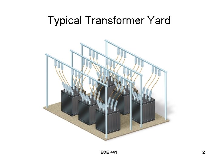
Typical Transformer Yard ECE 441 2
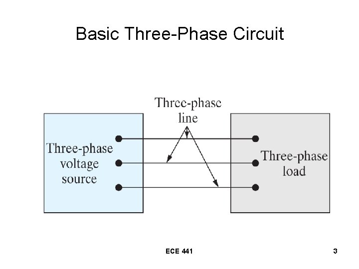
Basic Three-Phase Circuit ECE 441 3
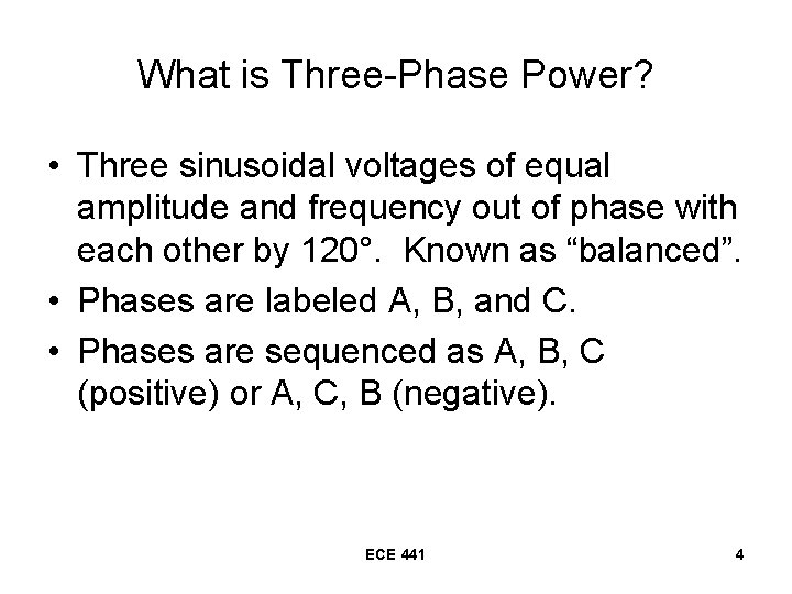
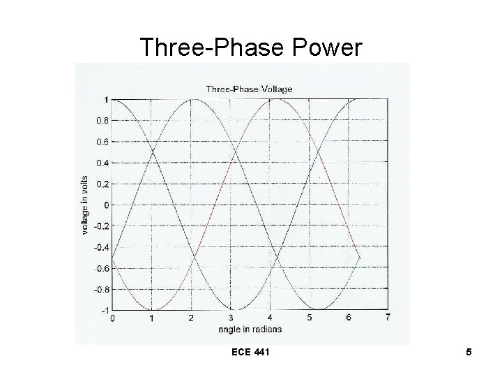
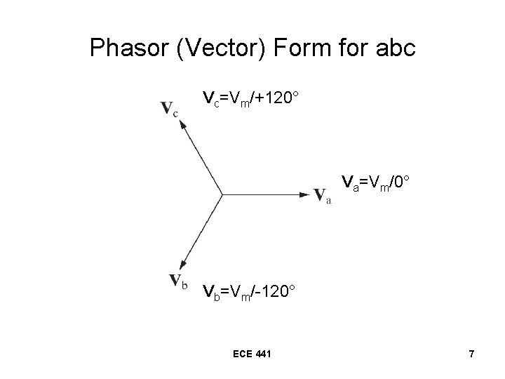
What is Three-Phase Power? • Three sinusoidal voltages of equal amplitude and frequency out of phase with each other by 120°. Known as “balanced”. • Phases are labeled A, B, and C. • Phases are sequenced as A, B, C (positive) or A, C, B (negative). ECE 441 4
Three-Phase Power ECE 441 5
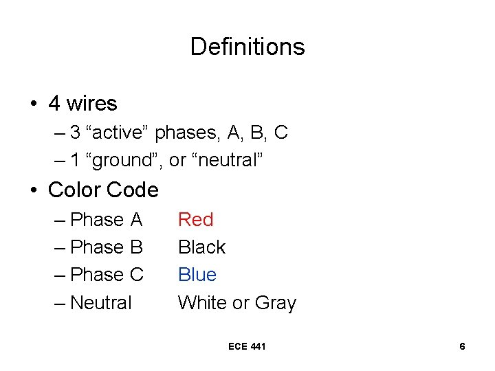
Definitions • 4 wires – 3 “active” phases, A, B, C – 1 “ground”, or “neutral” • Color Code – Phase A – Phase B – Phase C – Neutral Red Black Blue White or Gray ECE 441 6
Phasor (Vector) Form for abc Vc=Vm/+120° Va=Vm/0° Vb=Vm/-120° ECE 441 7
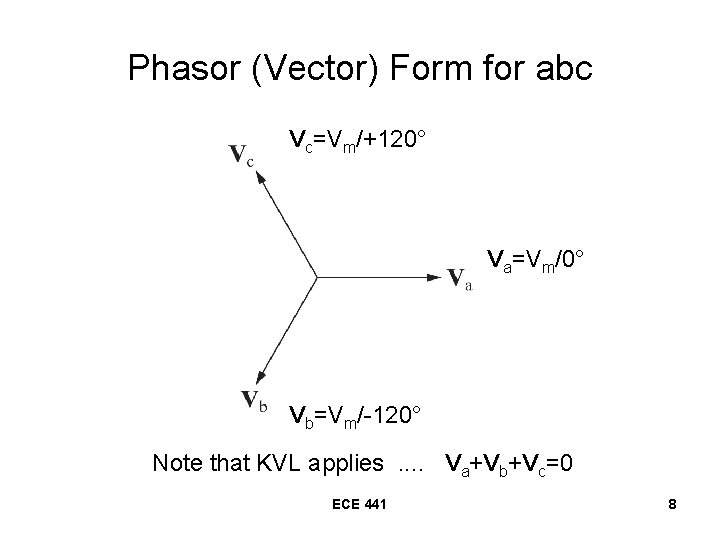
Phasor (Vector) Form for abc Vc=Vm/+120° Va=Vm/0° Vb=Vm/-120° Note that KVL applies. . Va+Vb+Vc=0 ECE 441 8
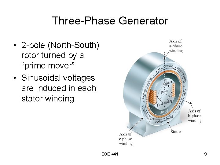
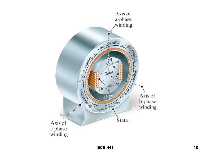
Three-Phase Generator • 2 -pole (North-South) rotor turned by a “prime mover” • Sinusoidal voltages are induced in each stator winding ECE 441 9
ECE 441 10
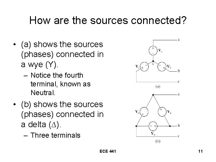
How are the sources connected? • (a) shows the sources (phases) connected in a wye (Y). – Notice the fourth terminal, known as Neutral. • (b) shows the sources (phases) connected in a delta (∆). – Three terminals ECE 441 11
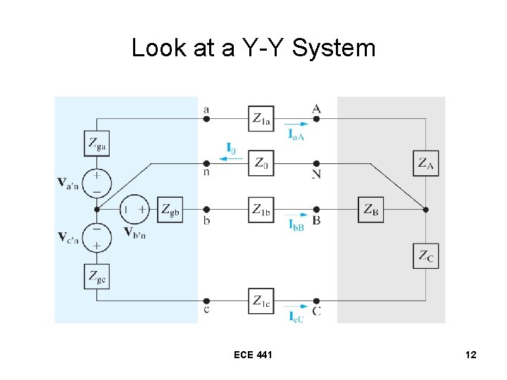
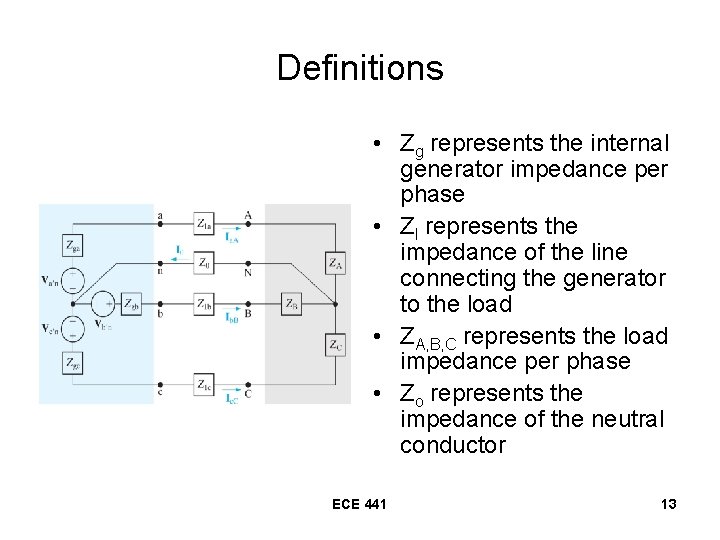
Look at a Y-Y System ECE 441 12
Definitions • Zg represents the internal generator impedance per phase • Zl represents the impedance of the line connecting the generator to the load • ZA, B, C represents the load impedance per phase • Zo represents the impedance of the neutral conductor ECE 441 13
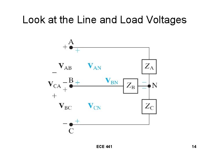
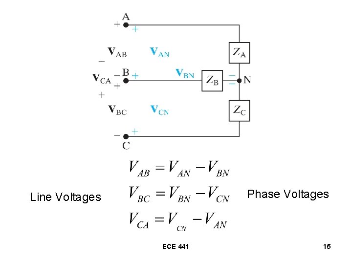
Look at the Line and Load Voltages ECE 441 14
Phase Voltages Line Voltages ECE 441 15
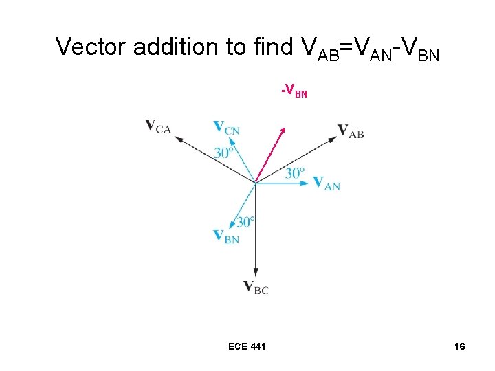
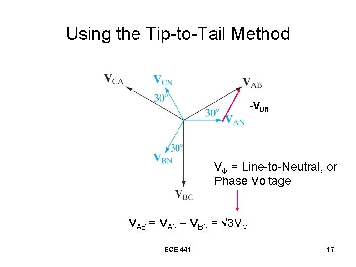
Vector addition to find VAB=VAN-VBN ECE 441 16
Using the Tip-to-Tail Method -VBN VΦ = Line-to-Neutral, or Phase Voltage VAB = VAN – VBN = √ 3 VΦ ECE 441 17
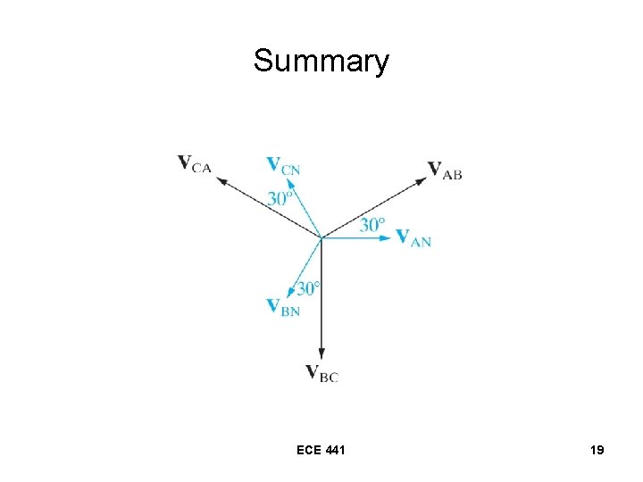
Conclusions for the Y connection • The amplitude of the line-to-line voltage is equal to √ 3 times the amplitude of the phase voltage. • The line-to-line voltages form a balanced set of 3 -phase voltages. • The set of line-to-line voltages leads the set of line-to-neutral (phase) voltages by 30°. ECE 441 18
Summary ECE 441 19
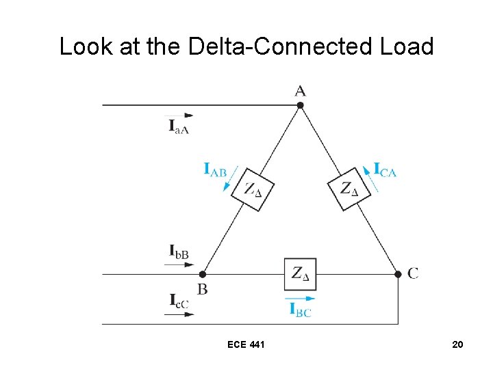
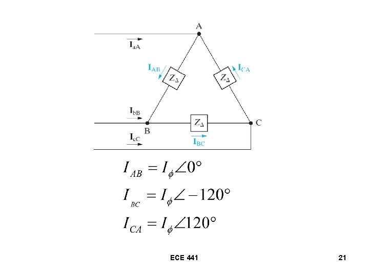
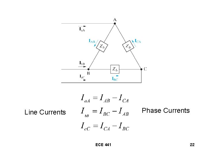
Look at the Delta-Connected Load ECE 441 20
ECE 441 21
Phase Currents Line Currents ECE 441 22
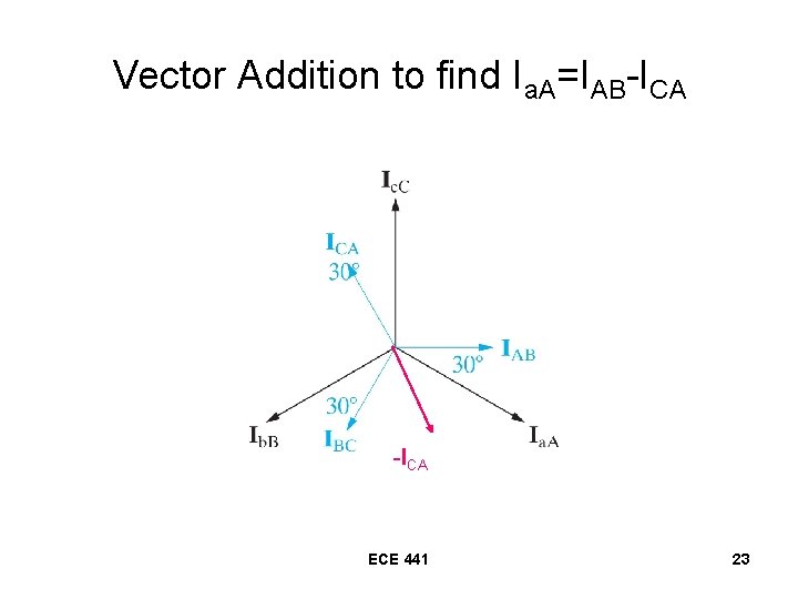
Vector Addition to find Ia. A=IAB-ICA ECE 441 23
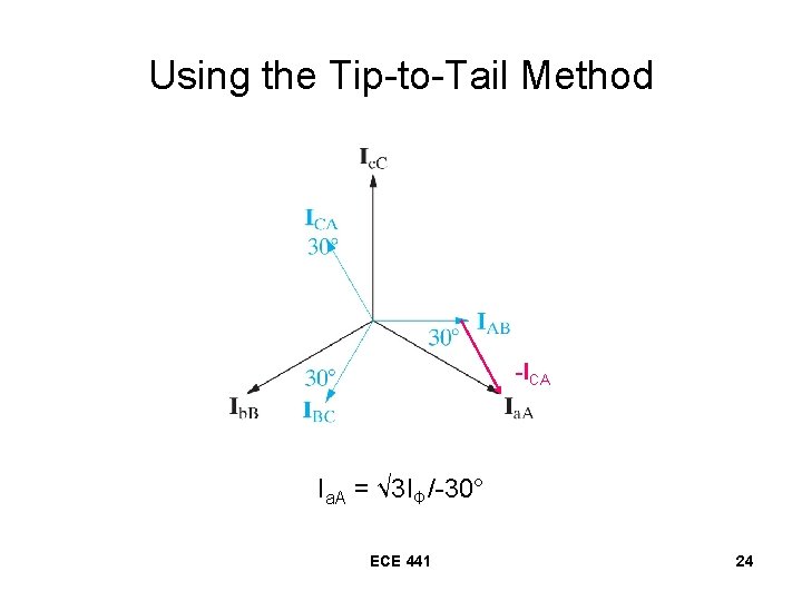
Using the Tip-to-Tail Method -ICA Ia. A = √ 3 IΦ/-30° ECE 441 24
Conclusions for the Delta Connection • The amplitude of the line current is equal to √ 3 times the phase current. • The set of line currents lags the phase currents by 30°. ECE 441 25