
Introduction to ThickLiquidWall Chambers Wayne R Meier Lawrence
Introduction to Thick-Liquid-Wall Chambers* Wayne R. Meier Lawrence Livermore National Lab Per Peterson UC Berkeley ARIES Meeting April 22 -23, 2002 * This work was performed under the auspices of the U. S. Department of Energy by the University of California, Lawrence Livermore National Laboratory under Contract No. W-7405 -Eng-48. ARIES HIF Modeling - WRM 4/22/02
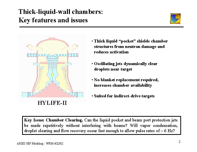
Thick-liquid-wall chambers: Key features and issues • Thick liquid “pocket” shields chamber structures from neutron damage and reduces activation • Oscillating jets dynamically clear droplets near target • No blanket replacement required, increases chamber availability • Suited for indirect-drive targets HYLIFE-II Key Issue: Chamber Clearing. Can the liquid pocket and beam port protection jets be made repetitively without interfering with beams? Will vapor condensation, droplet clearing and flow recovery occur fast enough to allow pulse rates of ~ 6 Hz? ARIES HIF Modeling - WRM 4/22/02 2
Why Thick Liquids? • Replace fusion materials questions with fluid mechanics questions – These are questions that can be answered without a $1 billion test facility • Maximize fusion power density – Bring final focus/transport elements close to target – Improve economics ARIES HIF Modeling - WRM 4/22/02 UC Berkeley
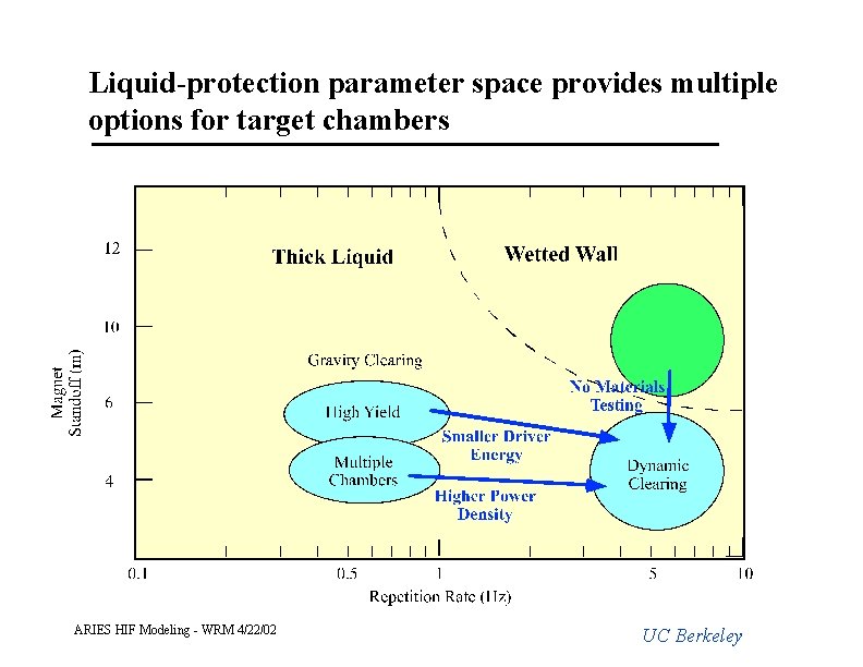
Liquid-protection parameter space provides multiple options for target chambers ARIES HIF Modeling - WRM 4/22/02 UC Berkeley
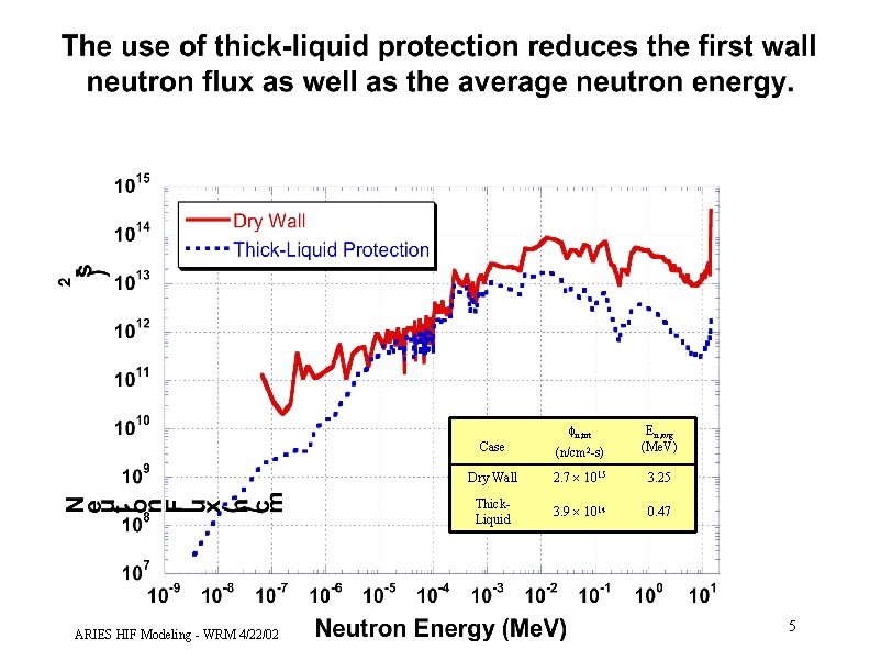
ARIES HIF Modeling - WRM 4/22/02 fn, tot Case (n/cm 2 -s) En, avg (Me. V) Dry Wall 2. 7 1015 3. 25 Thick. Liquid 3. 9 1014 0. 47 5
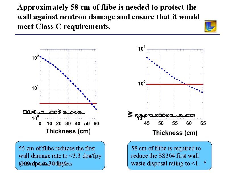
Approximately 58 cm of flibe is needed to protect the wall against neutron damage and ensure that it would meet Class C requirements. 55 cm of flibe reduces the first wall damage rate to <3. 3 dpa/fpy (100 dpa in 30 fpy). ARIES HIF Modeling - WRM 4/22/02 58 cm of flibe is required to reduce the SS 304 first wall waste disposal rating to <1. 6
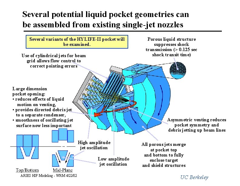
Several potential liquid pocket geometries can be assembled from existing single-jet nozzles Several variants of the HYLIFE-II pocket will be examined. Use of cylindrical jets for beam grid allows flow control to correct pointing errors Large dimension pocket opening: • reduces effects of liquid motion on venting, • provides directed debris jet to a separate condenser, • smoothness of oscillating jet surface now less important Asymmetric venting reduces pocket symmetry and debris jetting up beam lines High amplitude jet oscillation Low amplitude jet oscillation ARIES HIF Modeling - WRM 4/22/02 Porous liquid structure suppresses shock transmission (> 0. 125 sec shock transit time) All porous jets merge at pocket top and bottom to fully enclose target and shield structures UC Berkeley
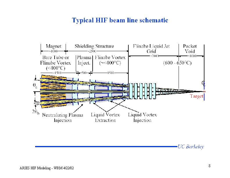
ARIES HIF Modeling - WRM 4/22/02 8
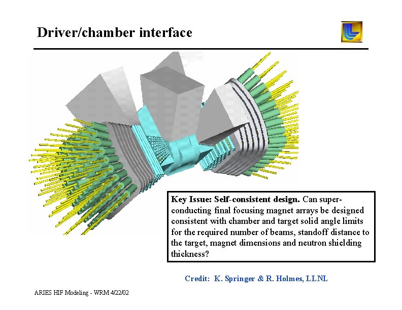
Driver/chamber interface Key Issue: Self-consistent design. Can superconducting final focusing magnet arrays be designed consistent with chamber and target solid angle limits for the required number of beams, standoff distance to the target, magnet dimensions and neutron shielding thickness? Credit: K. Springer & R. Holmes, LLNL ARIES HIF Modeling - WRM 4/22/02
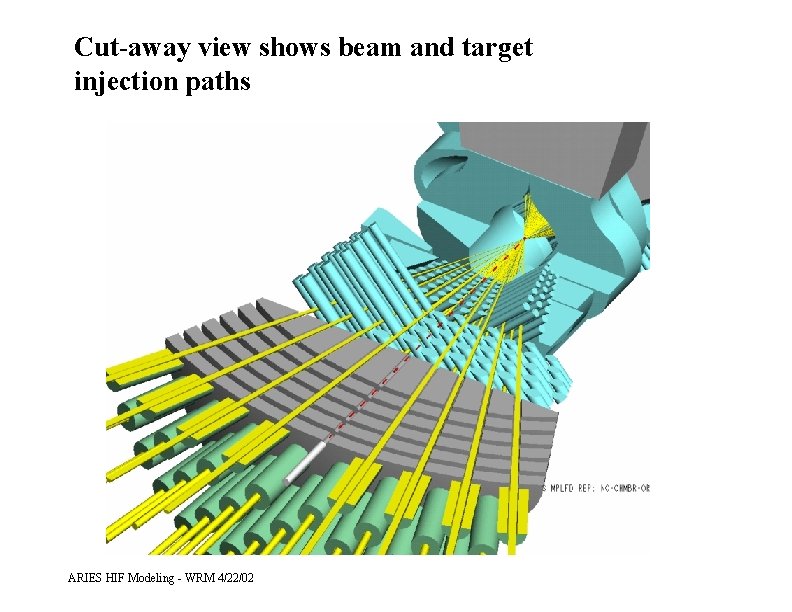
Cut-away view shows beam and target injection paths ARIES HIF Modeling - WRM 4/22/02
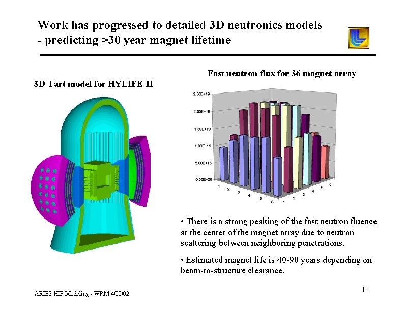
Work has progressed to detailed 3 D neutronics models - predicting >30 year magnet lifetime Fast neutron flux for 36 magnet array 3 D Tart model for HYLIFE-II • There is a strong peaking of the fast neutron fluence at the center of the magnet array due to neutron scattering between neighboring penetrations. • Estimated magnet life is 40 -90 years depending on beam-to-structure clearance. ARIES HIF Modeling - WRM 4/22/02 11
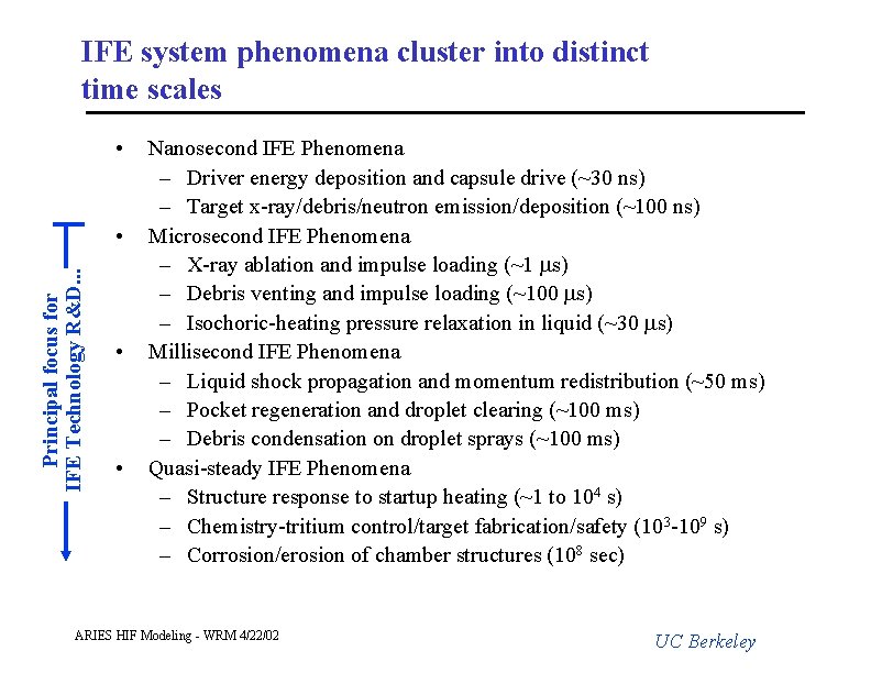
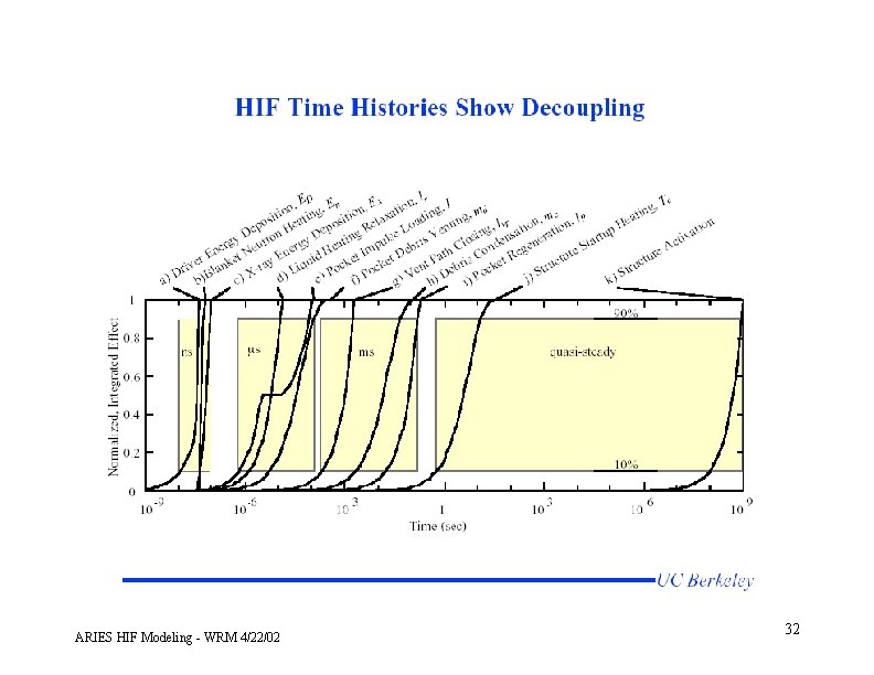
IFE system phenomena cluster into distinct time scales • Principal focus for IFE Technology R&D. . . • • • Nanosecond IFE Phenomena – Driver energy deposition and capsule drive (~30 ns) – Target x-ray/debris/neutron emission/deposition (~100 ns) Microsecond IFE Phenomena – X-ray ablation and impulse loading (~1 ms) – Debris venting and impulse loading (~100 ms) – Isochoric-heating pressure relaxation in liquid (~30 ms) Millisecond IFE Phenomena – Liquid shock propagation and momentum redistribution (~50 ms) – Pocket regeneration and droplet clearing (~100 ms) – Debris condensation on droplet sprays (~100 ms) Quasi-steady IFE Phenomena – Structure response to startup heating (~1 to 104 s) – Chemistry-tritium control/target fabrication/safety (103 -109 s) – Corrosion/erosion of chamber structures (108 sec) ARIES HIF Modeling - WRM 4/22/02 UC Berkeley
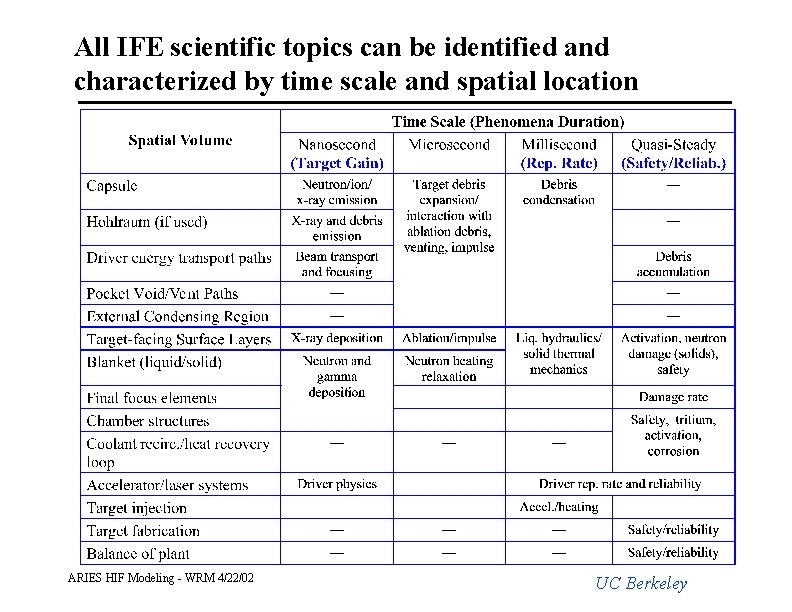
All IFE scientific topics can be identified and characterized by time scale and spatial location ARIES HIF Modeling - WRM 4/22/02 UC Berkeley
Millisecond Chamber Phenomena • Liquid pocket disruption and regeneration – Pressure waves travel large distances over millisecond time scales, so liquid flow is incompressible – Major liquid phenomena can be reproduced in scaled water experiments • Ablation and target debris condensation – Occurs on droplet sprays physically isolated from liquid pocket – Condenser region baffling optimized for recovery and concentration of volatiles (He, DT, Hg, etc. ) – Experiments can used pulsed power to generate vapor/plasma from prototypical chamber materials (UCLA work) ARIES HIF Modeling - WRM 4/22/02 UC Berkeley
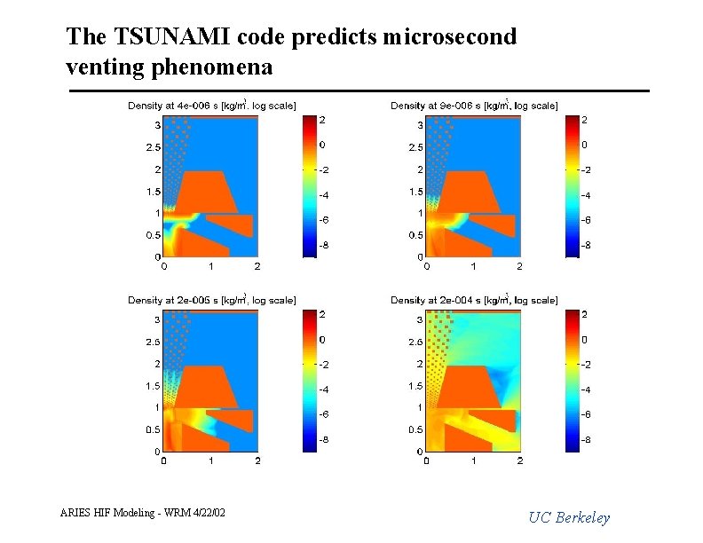
The TSUNAMI code predicts microsecond venting phenomena ARIES HIF Modeling - WRM 4/22/02 UC Berkeley
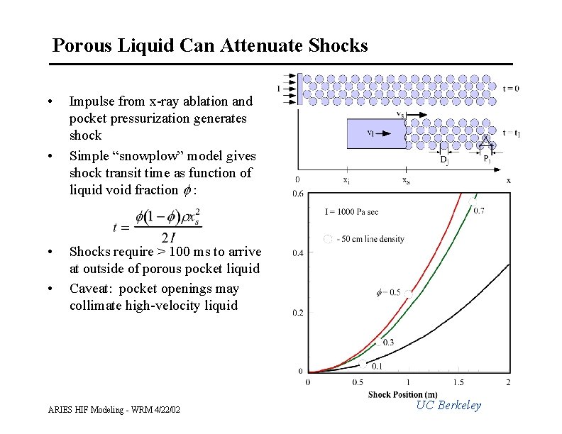
Porous Liquid Can Attenuate Shocks • • Impulse from x-ray ablation and pocket pressurization generates shock Simple “snowplow” model gives shock transit time as function of liquid void fraction f : Shocks require > 100 ms to arrive at outside of porous pocket liquid Caveat: pocket openings may collimate high-velocity liquid ARIES HIF Modeling - WRM 4/22/02 UC Berkeley
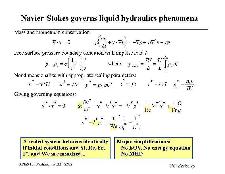
Navier-Stokes governs liquid hydraulics phenomena A scaled system behaves identically if initial conditions and St, Re, Fr, I*, and We are matched. . . ARIES HIF Modeling - WRM 4/22/02 Major simplifications: No EOS, No energy equation No MHD UC Berkeley
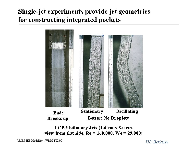
Single-jet experiments provide jet geometries for constructing integrated pockets Bad: Breaks up Stationary Oscillating Better: No Droplets UCB Stationary Jets (1. 6 cm x 8. 0 cm, view from flat side, Re = 160, 000, We = 29, 000) ARIES HIF Modeling - WRM 4/22/02 UC Berkeley
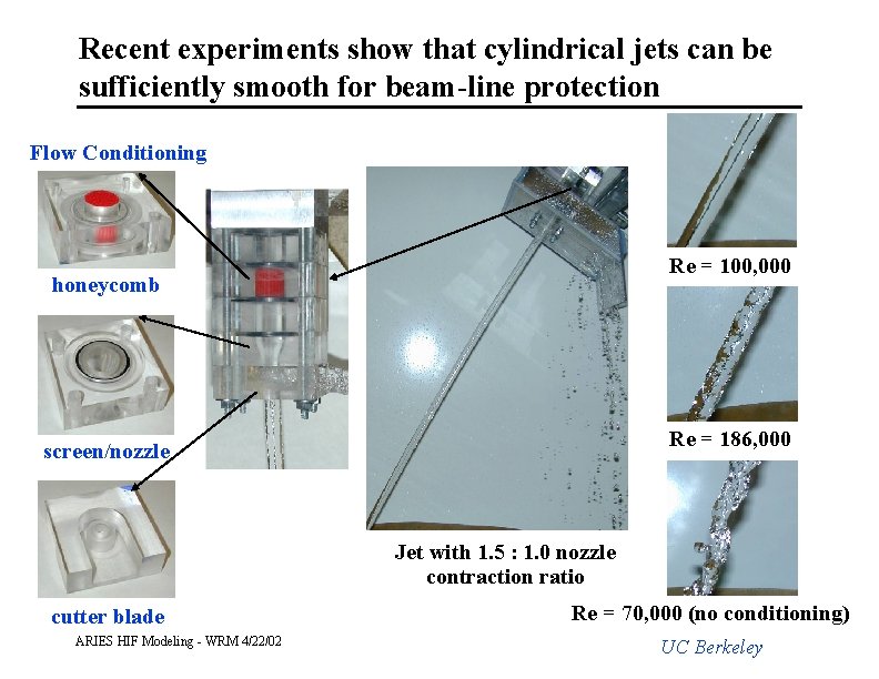
Recent experiments show that cylindrical jets can be sufficiently smooth for beam-line protection Flow Conditioning Re = 100, 000 honeycomb Re = 186, 000 screen/nozzle Jet with 1. 5 : 1. 0 nozzle contraction ratio cutter blade ARIES HIF Modeling - WRM 4/22/02 Re = 70, 000 (no conditioning) UC Berkeley
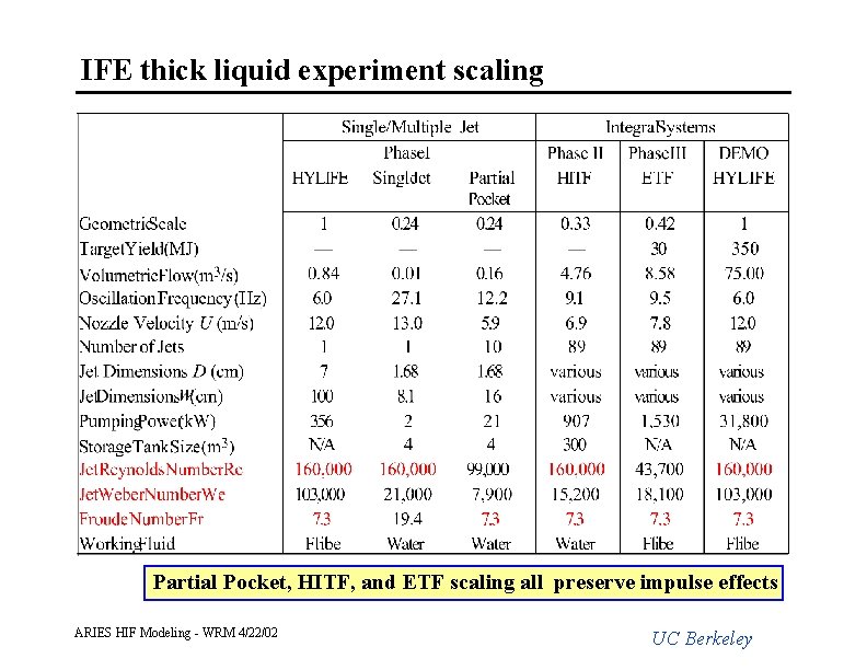
IFE thick liquid experiment scaling Partial Pocket, HITF, and ETF scaling all preserve impulse effects ARIES HIF Modeling - WRM 4/22/02 UC Berkeley
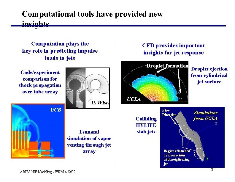
Computational tools have provided new insights Computation plays the key role in predicting impulse loads to jets CFD provides important insights for jet response Droplet formation Code/experiment comparison for shock propagation over tube array U. Wisc. UCLA UCB Tsunami simulation of vapor venting through jet array ARIES HIF Modeling - WRM 4/22/02 Droplet ejection from cylindrical jet surface Colliding HYLIFE slab jets Flow Direction Simulations from UCLA Regions flattened by interaction with neighboring jet 21
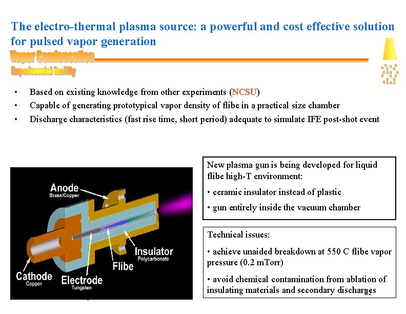
The electro-thermal plasma source: a powerful and cost effective solution for pulsed vapor generation • • • Based on existing knowledge from other experiments (NCSU) Capable of generating prototypical vapor density of flibe in a practical size chamber Discharge characteristics (fast rise time, short period) adequate to simulate IFE post-shot event New plasma gun is being developed for liquid flibe high-T environment: • ceramic insulator instead of plastic • gun entirely inside the vacuum chamber Technical issues: • achieve unaided breakdown at 550 C flibe vapor pressure (0. 2 m. Torr) ARIES HIF Modeling - WRM 4/22/02 • avoid chemical contamination from ablation of insulating materials and secondary discharges 22
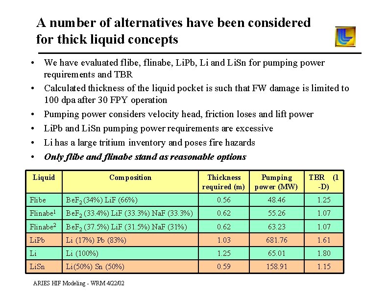
A number of alternatives have been considered for thick liquid concepts • We have evaluated flibe, flinabe, Li. Pb, Li and Li. Sn for pumping power requirements and TBR • Calculated thickness of the liquid pocket is such that FW damage is limited to 100 dpa after 30 FPY operation • Pumping power considers velocity head, friction loses and lift power • Li. Pb and Li. Sn pumping power requirements are excessive • Li has a large tritium inventory and poses fire hazards • Only flibe and flinabe stand as reasonable options Liquid Composition Thickness required (m) Pumping power (MW) TBR (1 -D) Flibe Be. F 2 (34%) Li. F (66%) 0. 56 48. 46 1. 25 Flinabe 1 Be. F 2 (33. 4%) Li. F (33. 3%) Na. F (33. 3%) 0. 62 55. 26 1. 07 Flinabe 2 Be. F 2 (37. 5%) Li. F (31. 5%) Na. F (31%) 0. 62 63. 23 1. 07 Li. Pb Li (17%) Pb (83%) 1. 03 681. 76 1. 61 Li Li (100%) 1. 25 65. 01 1. 80 Li. Sn Li(50%) Sn (50%) 0. 59 158. 91 1. 15 ARIES HIF Modeling - WRM 4/22/02
Some possible areas to for ARIES to study • Design space of blanket thickness/wall radius/radiation damage limits for different first wall structural materials – Possible higher damage limit thinner blanker or smaller chamber reduced pumping power and/or closer final focus magnets • Alternate structural material (ferritic, Si. C, C/C? ) and compatibility with flibe and hohlraum materials (D-K Sze? ) • Mechanical design of oscillating nozzle and flow conditioning system • Chamber/driver interface design issues/options ARIES HIF Modeling - WRM 4/22/02

More slides on thick liquid wall chambers ARIES HIF Modeling - WRM 4/22/02 25
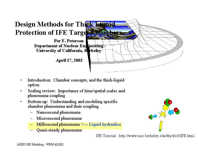
Design Methods for Thick Liquid Protection of IFE Target Chambers Per F. Peterson Department of Nuclear Engineering University of California, Berkeley April 17, 2002 • • • Introduction: Chamber concepts, and the thick-liquid option Scaling review: Importance of time/spatial scales and phenomena coupling Bottom up: Understanding and modeling specific chamber phenomena and their coupling – Nanosecond phenomena – Microsecond phenomena – Millisecond phenomena <--- Liquid hydraulics – Quasi-steady phenomena IFE Tutorial: http: //www. nuc. berkeley. edu/thyd/icf/IFE. html ARIES HIF Modeling - WRM 4/22/02
IFE target chamber must meet four requirements • Regenerate chamber conditions for target injection, driver beam propagation, and ignition at sufficiently high rates (i. e. 3 - 6 Hz) • Protect chamber structures for several to many years or allow easy replacement of inexpensive modular components • Extract fusion energy in high-temperature coolant, regenerate tritium • Reduce radioactive waste generation, inventory, and possible release fractions low enough to meet no-public-evacuation standards. Chamber will be 9 -15% of total capital cost Design, not chamber cost, is the most important issue ARIES HIF Modeling - WRM 4/22/02 UC Berkeley
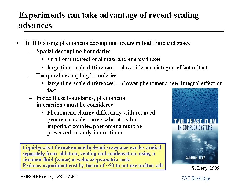
Experiments can take advantage of recent scaling advances • In IFE strong phenomena decoupling occurs in both time and space – Spatial decoupling boundaries • small or unidirectional mass and energy fluxes • large time scale differences—slow side sees integral effect of fast – Temporal decoupling boundaries • large time scale differences —slower phenomena sees integral effect of fast – Inside these boundaries, phenomena interactions must be considered • Phenomena change differently with reduced geometric scale, time scale ratios for important coupled phenomena must be preserved to study interactions Liquid pocket formation and hydraulic response can be studied separately from ablation, venting and condensation, using a simulant fluid (water) at reduced geometric scale. Reduces experiment cost by factor of ~50 to not use molten salt ARIES HIF Modeling - WRM 4/22/02 S. Levy, 1999 UC Berkeley
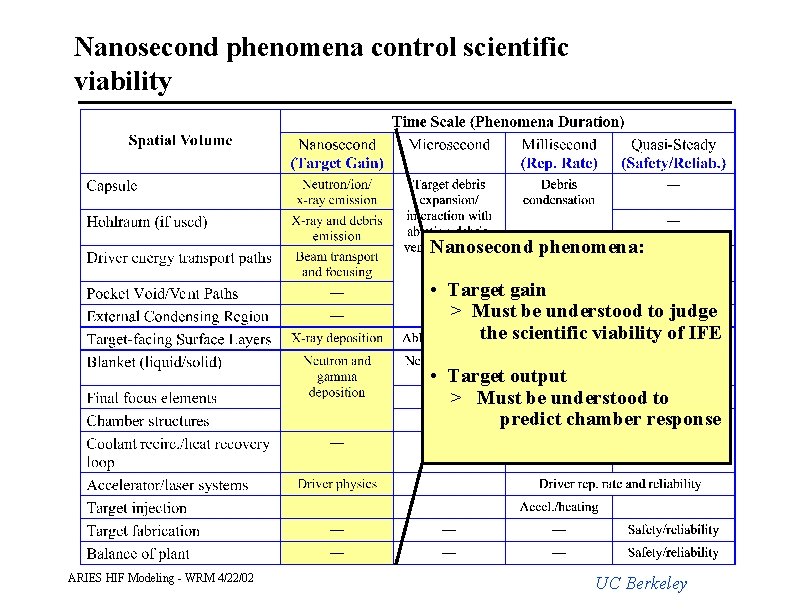
Nanosecond phenomena control scientific viability Nanosecond phenomena: • Target gain > Must be understood to judge the scientific viability of IFE • Target output > Must be understood to predict chamber response ARIES HIF Modeling - WRM 4/22/02 UC Berkeley
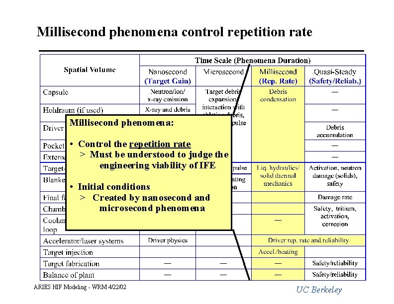
Millisecond phenomena control repetition rate Millisecond phenomena: • Control the repetition rate > Must be understood to judge the engineering viability of IFE • Initial conditions > Created by nanosecond and microsecond phenomena ARIES HIF Modeling - WRM 4/22/02 UC Berkeley
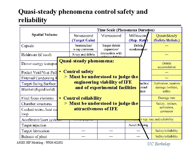
Quasi-steady phenomena control safety and reliability Quasi-steady phenomena: • Control safety > Must be understood to judge the engineering viability of IFE and of experimental facilities • Control reliability > Must be understood to judge the attractiveness of IFE ARIES HIF Modeling - WRM 4/22/02 UC Berkeley
ARIES HIF Modeling - WRM 4/22/02 32
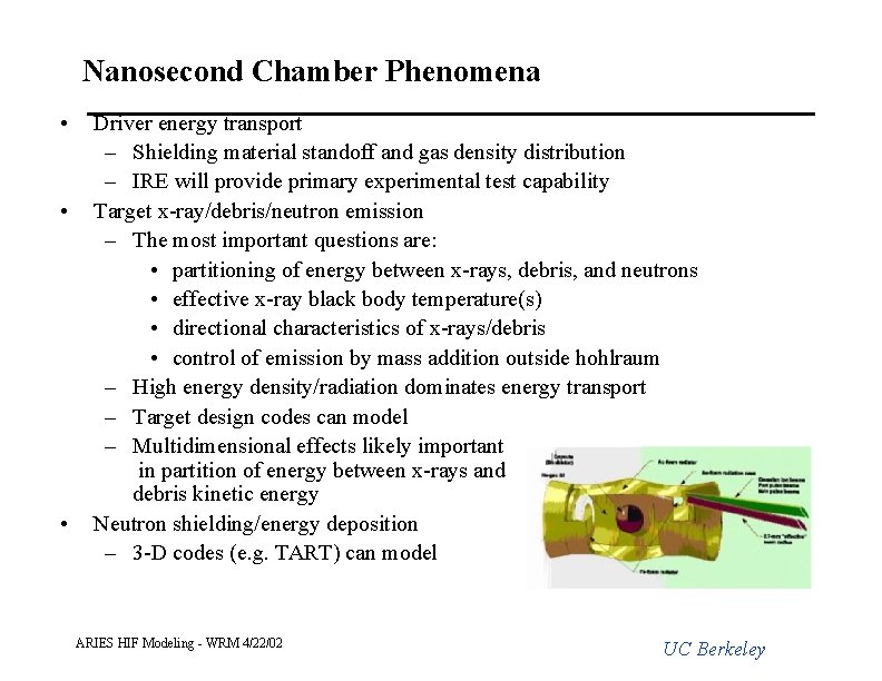
Nanosecond Chamber Phenomena • • • Driver energy transport – Shielding material standoff and gas density distribution – IRE will provide primary experimental test capability Target x-ray/debris/neutron emission – The most important questions are: • partitioning of energy between x-rays, debris, and neutrons • effective x-ray black body temperature(s) • directional characteristics of x-rays/debris • control of emission by mass addition outside hohlraum – High energy density/radiation dominates energy transport – Target design codes can model – Multidimensional effects likely important in partition of energy between x-rays and debris kinetic energy Neutron shielding/energy deposition – 3 -D codes (e. g. TART) can model ARIES HIF Modeling - WRM 4/22/02 UC Berkeley
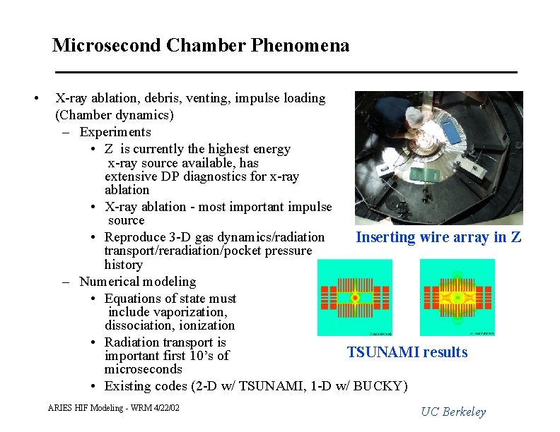
Microsecond Chamber Phenomena • X-ray ablation, debris, venting, impulse loading (Chamber dynamics) – Experiments • Z is currently the highest energy x-ray source available, has extensive DP diagnostics for x-ray ablation • X-ray ablation - most important impulse source • Reproduce 3 -D gas dynamics/radiation Inserting wire array in Z transport/reradiation/pocket pressure history – Numerical modeling • Equations of state must include vaporization, dissociation, ionization • Radiation transport is TSUNAMI results important first 10’s of microseconds • Existing codes (2 -D w/ TSUNAMI, 1 -D w/ BUCKY) ARIES HIF Modeling - WRM 4/22/02 UC Berkeley
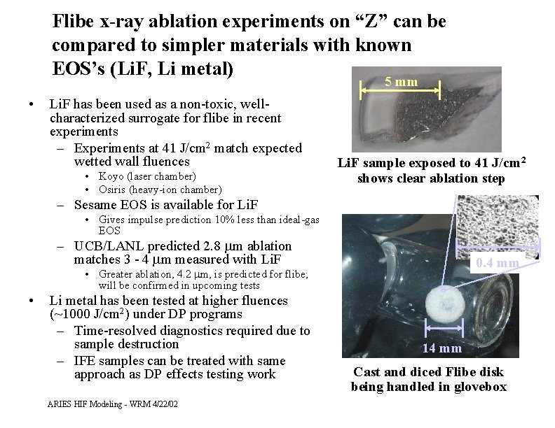
Flibe x-ray ablation experiments on “Z” can be compared to simpler materials with known EOS’s (Li. F, Li metal) 5 mm • Li. F has been used as a non-toxic, wellcharacterized surrogate for flibe in recent experiments – Experiments at 41 J/cm 2 match expected wetted wall fluences • Koyo (laser chamber) • Osiris (heavy-ion chamber) Li. F sample exposed to 41 J/cm 2 shows clear ablation step – Sesame EOS is available for Li. F • Gives impulse prediction 10% less than ideal-gas EOS – UCB/LANL predicted 2. 8 mm ablation matches 3 - 4 mm measured with Li. F 0. 4 mm • Greater ablation, 4. 2 mm, is predicted for flibe; will be confirmed in upcoming tests • Li metal has been tested at higher fluences (~1000 J/cm 2) under DP programs – Time-resolved diagnostics required due to sample destruction – IFE samples can be treated with same approach as DP effects testing work ARIES HIF Modeling - WRM 4/22/02 14 mm Cast and diced Flibe disk being handled in glovebox
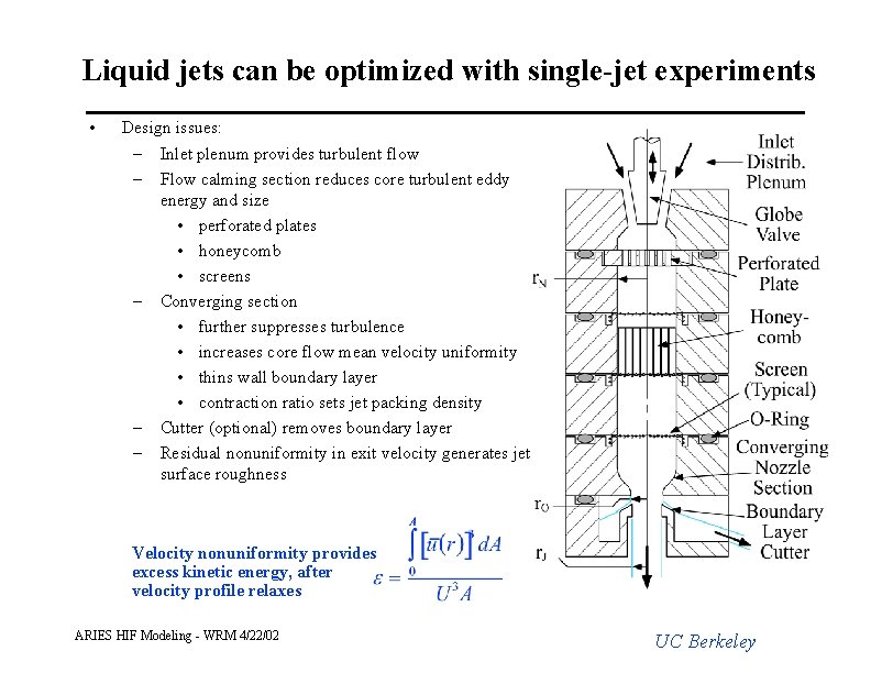
Liquid jets can be optimized with single-jet experiments • Design issues: – Inlet plenum provides turbulent flow – Flow calming section reduces core turbulent eddy energy and size • perforated plates • honeycomb • screens – Converging section • further suppresses turbulence • increases core flow mean velocity uniformity • thins wall boundary layer • contraction ratio sets jet packing density – Cutter (optional) removes boundary layer – Residual nonuniformity in exit velocity generates jet surface roughness Velocity nonuniformity provides excess kinetic energy, after velocity profile relaxes ARIES HIF Modeling - WRM 4/22/02 UC Berkeley
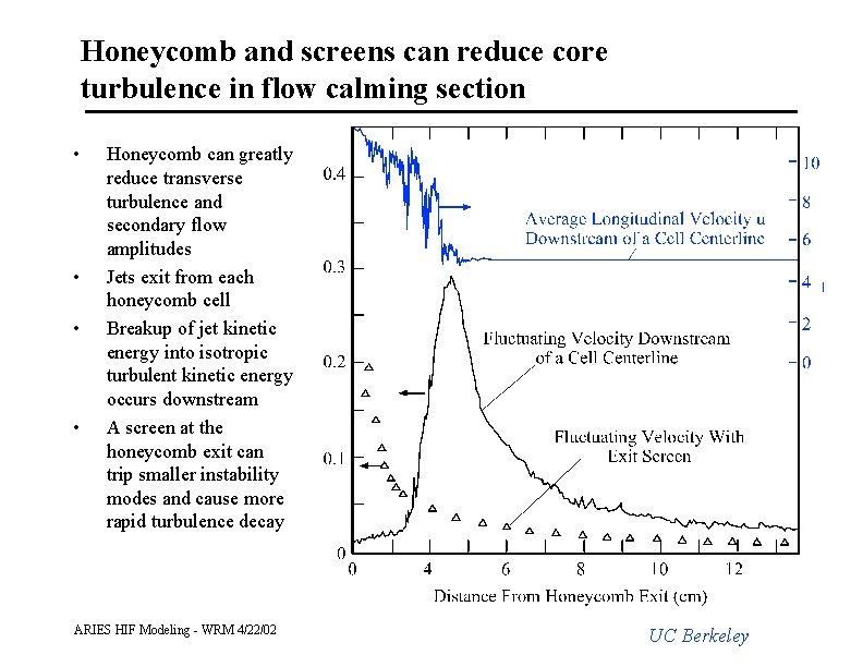
Honeycomb and screens can reduce core turbulence in flow calming section • • Honeycomb can greatly reduce transverse turbulence and secondary flow amplitudes Jets exit from each honeycomb cell Breakup of jet kinetic energy into isotropic turbulent kinetic energy occurs downstream A screen at the honeycomb exit can trip smaller instability modes and cause more rapid turbulence decay ARIES HIF Modeling - WRM 4/22/02 UC Berkeley
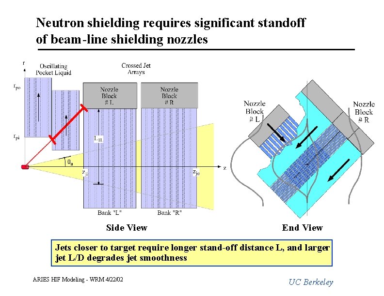
Neutron shielding requires significant standoff of beam-line shielding nozzles Side View End View Jets closer to target require longer stand-off distance L, and larger jet L/D degrades jet smoothness ARIES HIF Modeling - WRM 4/22/02 UC Berkeley
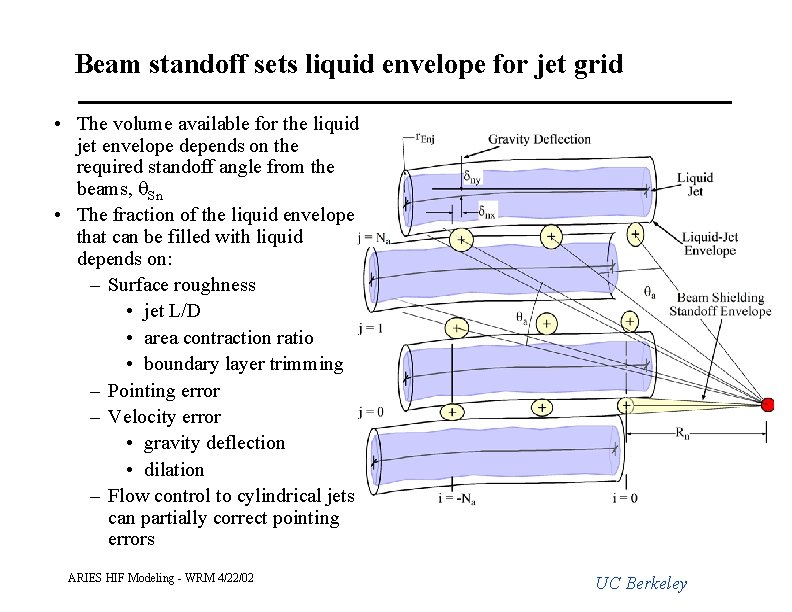
Beam standoff sets liquid envelope for jet grid • The volume available for the liquid jet envelope depends on the required standoff angle from the beams, q. Sn • The fraction of the liquid envelope that can be filled with liquid depends on: – Surface roughness • jet L/D • area contraction ratio • boundary layer trimming – Pointing error – Velocity error • gravity deflection • dilation – Flow control to cylindrical jets can partially correct pointing errors ARIES HIF Modeling - WRM 4/22/02 UC Berkeley
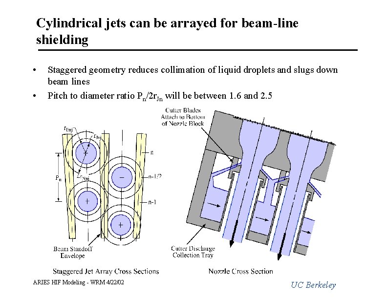
Cylindrical jets can be arrayed for beam-line shielding • • Staggered geometry reduces collimation of liquid droplets and slugs down beam lines Pitch to diameter ratio Pn/2 r. Jn will be between 1. 6 and 2. 5 ARIES HIF Modeling - WRM 4/22/02 UC Berkeley
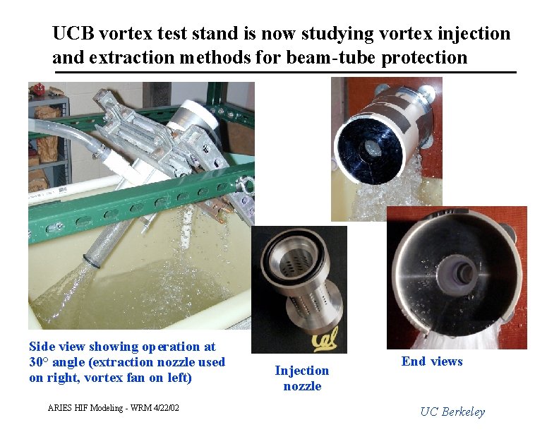
UCB vortex test stand is now studying vortex injection and extraction methods for beam-tube protection Side view showing operation at 30° angle (extraction nozzle used on right, vortex fan on left) ARIES HIF Modeling - WRM 4/22/02 Injection nozzle End views UC Berkeley
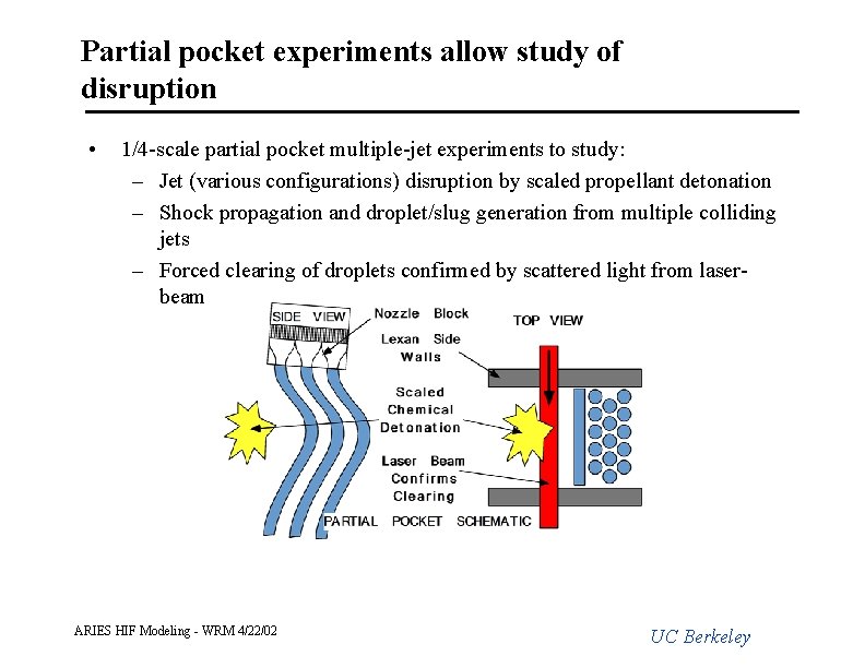
Partial pocket experiments allow study of disruption • 1/4 -scale partial pocket multiple-jet experiments to study: – Jet (various configurations) disruption by scaled propellant detonation – Shock propagation and droplet/slug generation from multiple colliding jets – Forced clearing of droplets confirmed by scattered light from laserbeam ARIES HIF Modeling - WRM 4/22/02 UC Berkeley
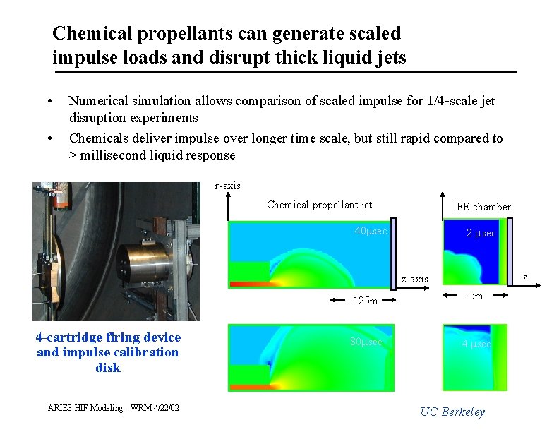
Chemical propellants can generate scaled impulse loads and disrupt thick liquid jets • • Numerical simulation allows comparison of scaled impulse for 1/4 -scale jet disruption experiments Chemicals deliver impulse over longer time scale, but still rapid compared to > millisecond liquid response r-axis Chemical propellant jet IFE chamber 40 msec 2 msec z z-axis 4 -cartridge firing device and impulse calibration disk ARIES HIF Modeling - WRM 4/22/02 . 125 m . 5 m 80 msec 4 msec UC Berkeley
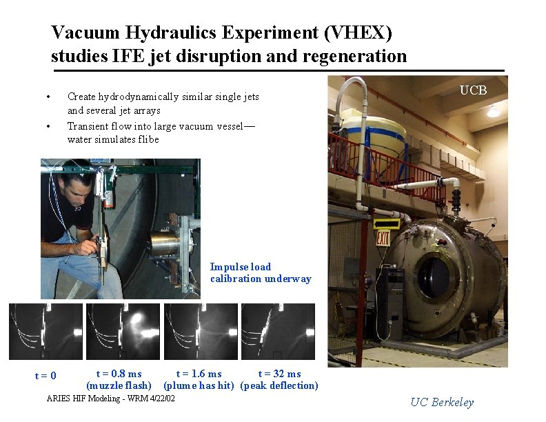
Vacuum Hydraulics Experiment (VHEX) studies IFE jet disruption and regeneration • • Create hydrodynamically similar single jets and several jet arrays Transient flow into large vacuum vessel— water simulates flibe UCB Impulse load calibration underway t=0 t = 0. 8 ms (muzzle flash) t = 1. 6 ms t = 32 ms (plume has hit) (peak deflection) ARIES HIF Modeling - WRM 4/22/02 UC Berkeley
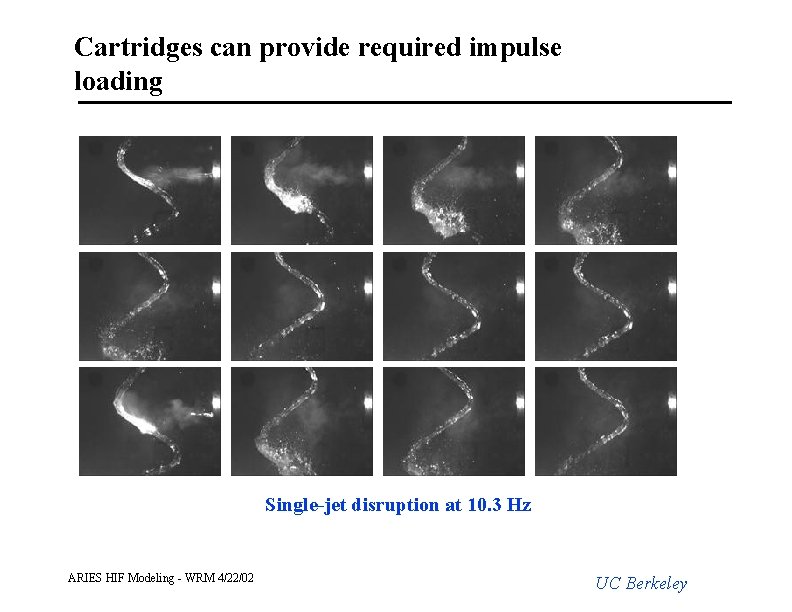
Cartridges can provide required impulse loading Single-jet disruption at 10. 3 Hz ARIES HIF Modeling - WRM 4/22/02 UC Berkeley
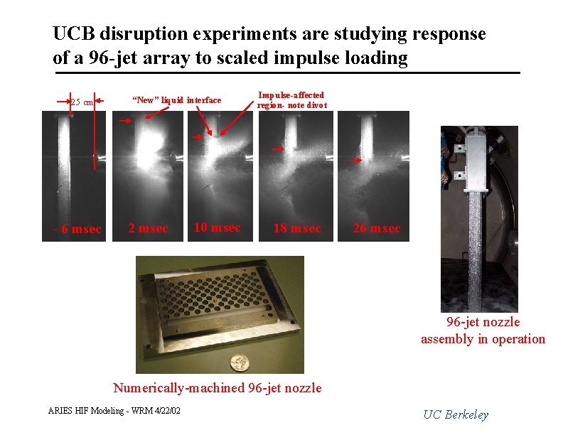
UCB disruption experiments are studying response of a 96 -jet array to scaled impulse loading 25 cm - 6 msec “New” liquid interface 2 msec 10 msec Impulse-affected region- note divot 18 msec 26 msec 96 -jet nozzle assembly in operation Numerically-machined 96 -jet nozzle ARIES HIF Modeling - WRM 4/22/02 UC Berkeley
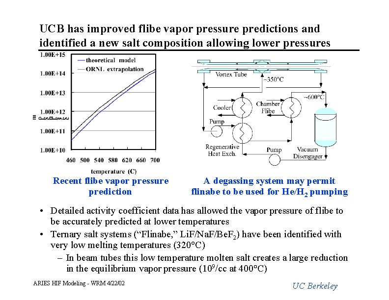
UCB has improved flibe vapor pressure predictions and identified a new salt composition allowing lower pressures Recent flibe vapor pressure prediction A degassing system may permit flinabe to be used for He/H 2 pumping • Detailed activity coefficient data has allowed the vapor pressure of flibe to be accurately predicted at lower temperatures • Ternary salt systems (“Flinabe, ” Li. F/Na. F/Be. F 2) have been identified with very low melting temperatures (320°C) – In beam tubes this low temperature molten salt creates a large reduction in the equilibrium vapor pressure (109/cc at 400°C) ARIES HIF Modeling - WRM 4/22/02 UC Berkeley
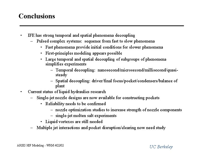
Conclusions • • IFE has strong temporal and spatial phenomena decoupling – Pulsed complex systems: sequence from fast to slow phenomena • Fast phenomena provide initial conditions for slower phenomena • First-principles modeling appears possible • Large temporal and spatial decoupling of subgroups of phenomena simplifies experiments – Temporal decoupling: nanosecond/microsecond/millisecond/quasisteady – Spatial decoupling: driver/final focus/pocket/condensers/balance of plant Current status of liquid hydraulics research – Single-jet nozzle designs are now available for constructing pockets • Reliability needs to be confirmed – nozzle optimization studies to increase strength of nozzle components – single-jet molten salt experiments • Liquid vortexes are still needed – Multiple jet interactions and pocket disruption/clearing now need study ARIES HIF Modeling - WRM 4/22/02 UC Berkeley
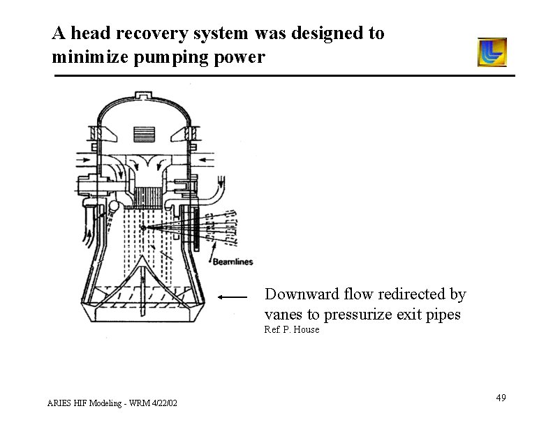
A head recovery system was designed to minimize pumping power Downward flow redirected by vanes to pressurize exit pipes Ref. P. House ARIES HIF Modeling - WRM 4/22/02 49
- Slides: 49