Introduction to RF at ISIS Lecture 16 February

Introduction to RF at ISIS Lecture, 16 February 2006 David Findlay Accelerator Division ISIS Department Rutherford Appleton Laboratory ISIS OPTIMVS NEVTRONVM SPALLATIONENSIVM FONS MVNDI

From ISIS MCR Beam News 3 -NOV-2005 00: 04 A burnt out valve base has been found on system 4 RF. We are in the process of changing it. Further update at 03: 00 Hrs. 17 -NOV-2005 13: 30 The beam tripped due to Modulator 3 tripping off. Whilst attempting to bring RF back on a large breakdown was heard in the feedline / 116 Valve area. We have investigated the problem and found a significant water leak. Experts are in attendance to rectify the problem. Update at 14. 30 Hours. 2 2

What is RF? RF = Radio frequency Used as shorthand for Alternating voltages at radio frequencies Alternating currents at radio frequencies Electromagnetic waves at radio frequencies Power carried in electromagnetic waves Apparatus generating RF power. . . 3 3

What are radio frequencies? Long waves ~200 k. Hz Medium waves ~1 MHz Short waves ~3 – 30 MHz VHF radio ~100 MHz TV ~500 MHz Mobile phones ~1000 – 2000 MHz Satellite TV ~10000 MHz Accelerators ~1 MHz – 10000 MHz http: //www. ofcom. org. uk/static/archive/ra/publication/ra_info/ra 365. htm#table 4 4

Wavelengths and frequencies? c=lf Velocity = wavelength × frequency Velocity of light = 3× 10⁸ metres/second = 186, 000 miles/second = 670, 000 miles/hour = 300 m/µs (300 m twice around the synchrotron) 5 5

Frequencies Wavelengths Long waves ~200 k. Hz ~1500 m Medium waves ~1 MHz ~300 m Short waves ~3 – 30 MHz ~10 – 100 m VHF radio ~100 MHz ~3 m TV ~500 MHz ~2 feet Mobile phones ~1000 – 2000 MHz ~6 – 12 inches Satellite TV ~10000 MHz ~1 inch Accelerators ~1 MHz – 10000 MHz 240 VAC mains 50 Hz ~4000 miles 6 6

Relative size matters 7 7

BBC Droitwich transmitter — Long wave Radio 4 8

Marconi’s transmitter, 1902 — Nova Scotia 9

Marconi’s spark transmitter, 1910 10

Steam engine and alternator 11

Two of four 5 k. V DC generators 12
 (cf. RAL SC")
12 k. V stand-by battery (6000 cells! 2 GJ stored energy!) (cf. RAL SC 3: 5 J) 13

Marconi’s 1920 valve transmitter 14

Alternating voltages, currents, electric fields, magnetic fields, . . . Need to describe by three quantities Frequency, amplitude and phase E. g. three-phase AC mains: All phases “ 240 V” But different phases are very different! Phase varies along a wire carrying alternating current How much phase changes depends on wavelength and hence on frequency 15 15
 = A sin (2 p f t + f) f")
Phase Alternating voltage V(t) = A sin (2 p f t + f) f = 240° 120° 0° E. g. three-phase AC mains 16 16

50 Hz AC mains in house House 4000 miles 17 17

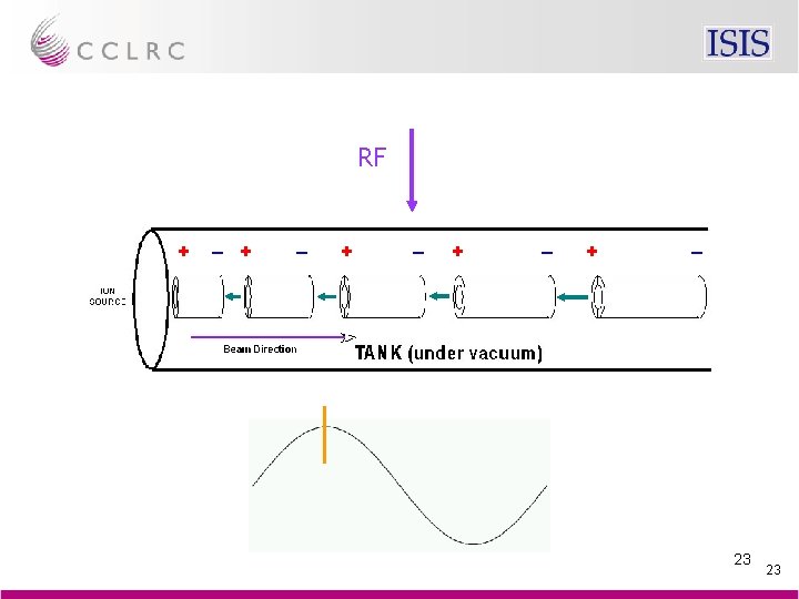
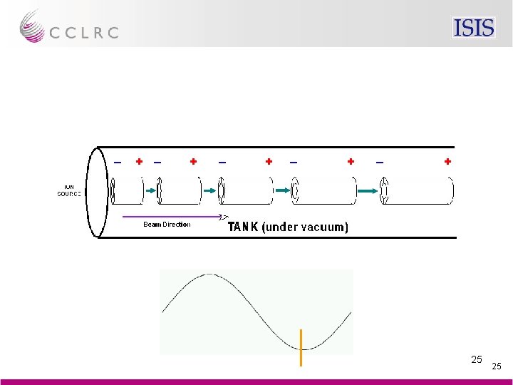
200 MHz RF in ISIS linac Positive 2½ feet Negative 5 feet 18 18

Why is RF used at all in accelerators? Cathode ray tube in TV set doesn’t need RF 19 19

Particles accelerated using electric field For 100 ke. V can use 100 k. V DC power supply unit. Even 665 k. V for old Cockcroft-Walton But 800, 000 V DC power supply unit for accelerating protons in ISIS not possible Instead, for high energies, use RF fields, and pass particles repeatedly through these fields RF fields produce bunched beams DC RF ns – µs spacing 20 20

Air Sound waves set up inside milk bottle RF Electromagnetic waves set up inside hollow metal cylinder 21 21

RF 22 22

24 24

26 26

Interior of linac tank 27

How much RF power? All beam power from RF ISIS mean current 200 µA Linac 70 Me. V Synchrotron 800 Me. V 70 Me. V × 200 µA = 14 k. W 800 Me. V × 200 µA = 160 k. W So need >14 k. W RF for linac, >160 k. W RF for synchrotron Linac pulsed, 2% duty factor 14 k. W ÷ 0. 02 = 0. 7 MW Synchrotron pulsed, 50% duty factor 160 k. W ÷ 0. 50 = 0. 3 MW 28 28

Two commercial 0. 5 MW short wave radio transmitters 29 29

RF powers Big radio and TV transmitters 0. 5 MW Mobile phone transmitters 30 W Mobile phones 1 W Sensitivity of mobile phones 10– 10 W ISIS linac 3 × 2 MW + 1 × 1 MW ISIS synchrotron 6 × 150 k. W + 4 × 75 k. W 30 30

Where does RF power come from? Big amplifiers Usually purpose built The basics: Accelerator Frequency source RF amplifier 31 31

~1 W RF ~1 MW RF 32

Devices that amplify RF Transistors ~100 watts maximum per transistor Couple lots together for kilowatts Valves / vacuum tubes Triodes, tetrodes Largest can deliver several megawatts (peak) Klystrons High powers, high gains Limited to frequencies >300 MHz IOTs (inductive output tubes) Often used in TV transmitters (esp. digital TV) Output limited to ~50 k. W 33 33
 Essentially minority carrier device But RF transistors usually")
Transistors usually junction transistors (NPN, PNP) Essentially minority carrier device But RF transistors usually field effect transistors Majority carrier device 34 34

Field effect transistor 35

Typical RF MOSFET 36

Solid state RF amplifier: few watts in, 3 k. W max out 37

3 k. W max. solid state amplifier mounted in rack 38

1 k. W solid state driver RF amplifier for synchrotron 39

Valves / vacuum tube made in 1915 40

Load + Anode power supply Anode Electrons – Grid Cathode Heater Basic triode circuit 41

Valve-based audio hi-fi amplifiers 42

Debuncher amplifier: commercial TV transmitter 43

Linac triode 5 MW peak 75 k. W mean Synchrotron tetrode 1000 k. W peak 350 k. W mean 44

Typical valve parameters at ISIS Type Heater Anode volts Anode current Peak power o/p Mean power o/p Cooling water TH 116 Triode 20 V, 500 A 35 k. V 175 A 2 MW 40 k. W 100 l/min 4648 Tetrode 4 V, 1600 A 16 k. V 8 A 75 k. W 40 k. W 200 l/min 45 45

Resonant circuits L C Parallel LC-circuit Impedance Z “infinite” at f = f 0 (2 f 0)² = 1 / LC Shorted line Impedance Z “infinite” at l = /4, 3 /4, 5 /4, . . . length l Only ratio of diameters matters 46 46
 Output Tetrode Input Anode Screen grid Control grid Cathode Heater Essence of")
HT (+ve) Output Tetrode Input Anode Screen grid Control grid Cathode Heater Essence of a tuned RF amplifier — 1 47 47
 Output Tetrode Input Anode Screen grid Control grid Cathode Heater Essence of")
HT (+ve) Output Tetrode Input Anode Screen grid Control grid Cathode Heater Essence of a tuned RF amplifier — 2 48 48
 tuned circuit Tetrode Output (anode) tuned circuit ISIS RFQ 200 k. W")
Input (grid) tuned circuit Tetrode Output (anode) tuned circuit ISIS RFQ 200 k. W tetrode driver 49
 IOT gain ~25 d. B")
Klystron gain ~50 d. B (× 105 power gain) IOT gain ~25 d. B (× 300 power gain) E. g. 10 W in, 1 MW out E. g. 200 W in, 60 k. W out 50 50

5 metres, 3 tons Toshiba E 3740 A 3 MW 324 MHz klystron 51

Skin depth RF currents flow in surface of conductor only Skin depth d µ 1 / Ö (frequency) (exponential) In copper, d = 7 / Ö (frequency) (cm) 50 Hz 1 cm 1 MHz 70 µm 200 MHz 5 µm In sea water 50 Hz ~100 feet 10 k. Hz ~10 feet ELF / submarines VLF / submarines 52 52

ISIS RFQ — vessel copper-plated stainless steel 53

Different currents on different surfaces of same piece of metal Linac high power RF amplifier 54

Dielectric material No external electric field Atoms – + – + Electric field 55 55

Dielectric material Dielectric constant Ceramic 6 Nylon 3 Perspex 3½ Polystyrene 2½ Water 80 Loss tangent — leads to dielectric heating Ceramic 0. 001 Nylon 0. 02 Perspex 0. 01 Polystyrene 0. 0001 Water 0. 1 — microwave ovens 56 56

Accelerating cavity Beam Vacuum Air RF amplifier Vacuum RF Window 57 57

RF feed to linac tank 58

Window and aperture 59

Good and failed RF windows 60

Cavity n Low level RF Phase comp. Volt. comp. RF amp. chain V ref. accel. field Phase comp. Motor drive Tuner beam Servo systems on amplitude, phase and cavity tuning Linac RF block diagram 61

Three amplifiers in previous slide 62

Synchrotron high power RF systems 63

Frequency sweeper Beam compensation loop Voltage loop Cavity tuning Phase loop Synchrotron low-level RF systems block diagram 64

Driver amplifier 65

Cavity and high power RF driver 66

High power RF drive 67

ISIS depends almost entirely on RF Earth ↓ DC 35 ke. V ↓ RF 665 ke. V ↓ RF 0. 004% 99. 996% 70 Me. V ↓ RF 800 Me. V 68 68

69 69
/(V/cm)")
Supplementary detail RF transistors — hand-waving Electron and hole mobilities in Si ~1000 (cm/s)/(V/cm) Breakdown field strength in Si is ~300 k. V/cm So maximum speed of electron or hole in Si is ~3× 10^8 cm/s = 0. 01 c In big transistor say characteristic size = 1 cm So electron or hole would take ~3 ns to travel across/through transistor RF period must be >> 3 ns, say 10 ns, thereby limiting RF frequency to 100 MHz If make transistor bigger to dissipate more heat, then more and more limited in frequency 70 70
- Slides: 70