
Introduction to particle accelerators Walter Scandale CERN AT
![Other applications of Proton Drivers Type of accelerator Energy [Ge. V] duty factor DF](https://slidetodoc.com/presentation_image_h2/fef6e17211c2c590e3a0f021b1a5c94d/image-30.jpg "Other applications of Proton Drivers Type of accelerator Energy [Ge. V] duty factor DF")
- Slides: 35
Introduction to particle accelerators Walter Scandale CERN - AT department Roma, marzo 2006
Lecture VI - neutrino projects topics Superbeam & Neutrino Factory & Muon Collider Target Proton driver
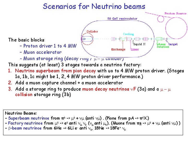
Scenarios for Neutrino beams The basic blocks – Proton driver 1 to 4 MW – Muon accelerator - Muon storage ring (decay ring / m - m collider) This suggests (at least) 3 stages towards a neutrino factory: 1. Neutrino superbeam from pion decay with uo to 4 MW proton driver. (Stages 1 a, 1 b, 1 c might be 1, 2, 4 MW proton driver performance. ) 2. Add a muon capture channel + a muon accelerator 3. Add a storage ring to produce muon decay neutrinos F (3 a) and a m - m collision storage ring (3 b) Neutrino Beams: – Superbeam neutrinos from π± -> m± + m (anti m). (Pions from p. A -> π±X. ) – Factory neutrinos from m± -> e± anti m e ( m anti me). (Muons from π± -> m± + m (anti m) ) – b-beam neutrinos from 6 He -> 6 Li e- anti e, 18 Ne -> 18 Fe+ e
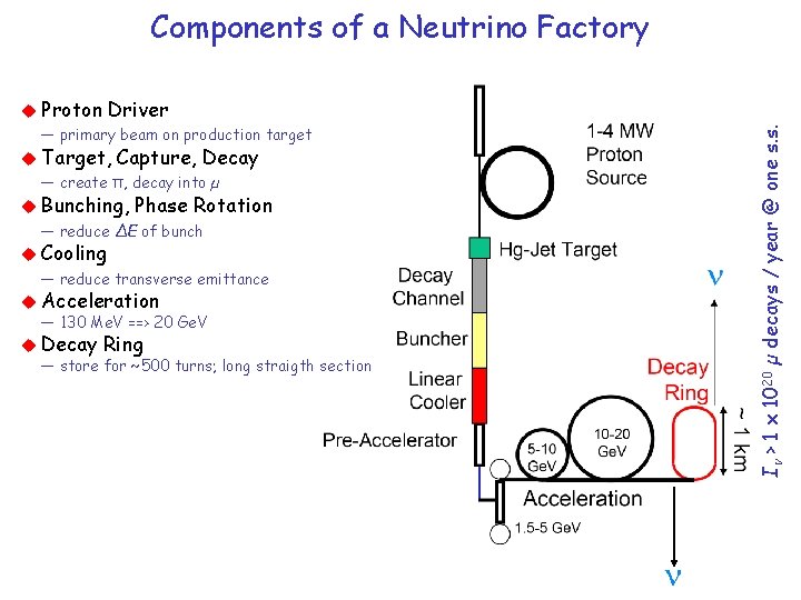
Components of a Neutrino Factory Driver — primary beam on production target Target, Capture, Decay — create π, decay into µ Bunching, Phase Rotation — reduce ∆E of bunch Cooling — reduce transverse emittance Acceleration — 130 Me. V ==> 20 Ge. V Decay Ring — store for ~500 turns; long straigth section I > 1 x 10²⁰ µ decays / year @ one s. s. Proton
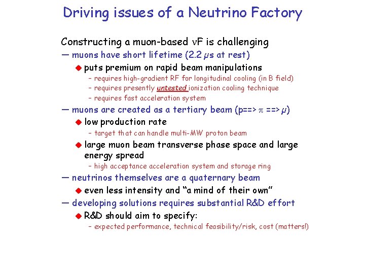
Driving issues of a Neutrino Factory Constructing a muon-based F is challenging — muons have short lifetime (2. 2 µs at rest) puts premium on rapid beam manipulations – requires high-gradient RF for longitudinal cooling (in B field) – requires presently untested ionization cooling technique – requires fast acceleration system — muons are created as a tertiary beam (p==> p ==> µ) low production rate – target that can handle multi-MW proton beam large muon beam transverse phase space and large energy spread – high acceptance acceleration system and storage ring — neutrinos themselves are a quaternary beam even less intensity and “a mind of their own” — developing solutions requires substantial R&D effort R&D should aim to specify: – expected performance, technical feasibility/risk, cost (matters!)
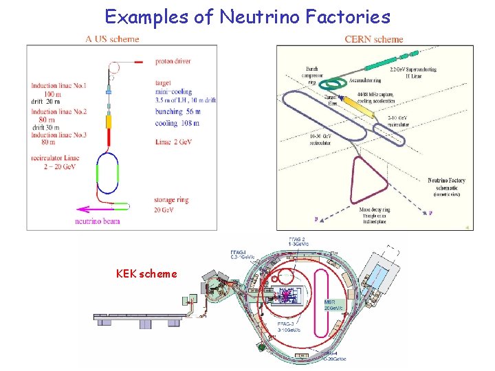
Examples of Neutrino Factories KEK scheme
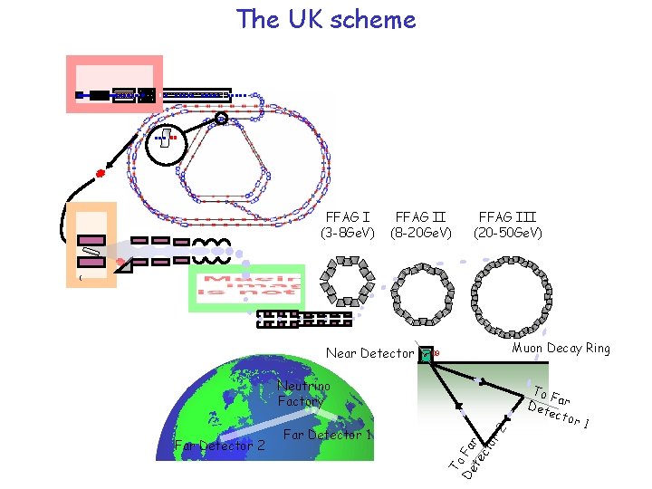
The UK scheme FFAG I (3 -8 Ge. V) FFAG II (8 -20 Ge. V) FFAG III (20 -50 Ge. V) ( Near Detector Muon Decay Ring R 109 Far Detector 2 Far Detector 1 To De Fa te r ct or 2 Neutrino Factory To F Det ar ecto r 1
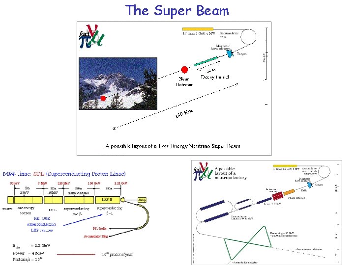
The Super Beam
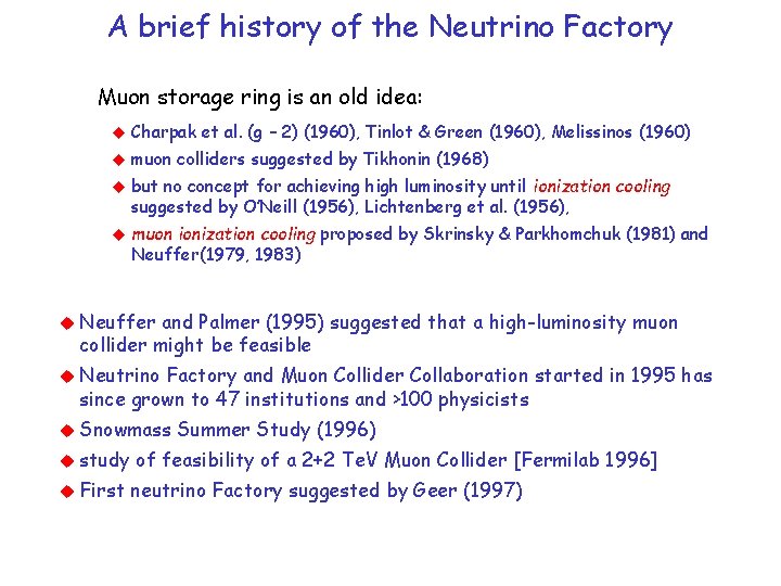
A brief history of the Neutrino Factory Muon storage ring is an old idea: Charpak et al. (g – 2) (1960), Tinlot & Green (1960), Melissinos (1960) muon colliders suggested by Tikhonin (1968) but no concept for achieving high luminosity until ionization cooling suggested by O’Neill (1956), Lichtenberg et al. (1956), muon ionization cooling proposed by Skrinsky & Parkhomchuk (1981) and Neuffer(1979, 1983) Neuffer and Palmer (1995) suggested that a high-luminosity muon collider might be feasible Neutrino Factory and Muon Collider Collaboration started in 1995 has since grown to 47 institutions and >100 physicists Snowmass study First Summer Study (1996) of feasibility of a 2+2 Te. V Muon Collider [Fermilab 1996] neutrino Factory suggested by Geer (1997)
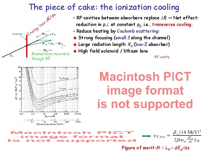
The piece of cake: the ionization cooling gy E r ne s los / d. E dx Momentum recovery though RF - RF cavities between absorbers replace E –> Net effect: reduction in p at constant p||, i. e. , transverse cooling. - Reduce heating by Coulomb scattering: Strong focusing (small ß along the channel) Large radiation length Xo (low-Z absorber) High field solenoid / lithium lens RF cavity Figure of merit: M = LR d. E /ds
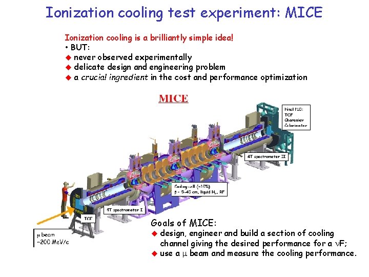
Ionization cooling test experiment: MICE Ionization cooling is a brilliantly simple idea! • BUT: never observed experimentally delicate design and engineering problem a crucial ingredient in the cost and performance optimization Goals of MICE: design, engineer and build a section of cooling channel giving the desired performance for a F; use a m beam and measure the cooling performance.
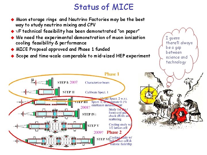
Status of MICE Muon storage rings and Neutrino Factories may be the best way to study neutrino mixing and CPV F technical feasibility has been demonstrated “on paper” We need the experimental demonstration of muon ionization cooling feasibility & performance MICE Proposal approved and Phase 1 funded Scope and time-scale comparable to mid-sized HEP experiment I guess there’ll always be a gap between science and technology
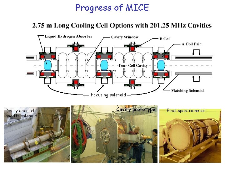
Progress of MICE Focusing solenoid Decay channel and its solenoid Cavity prototype Final spectrometer
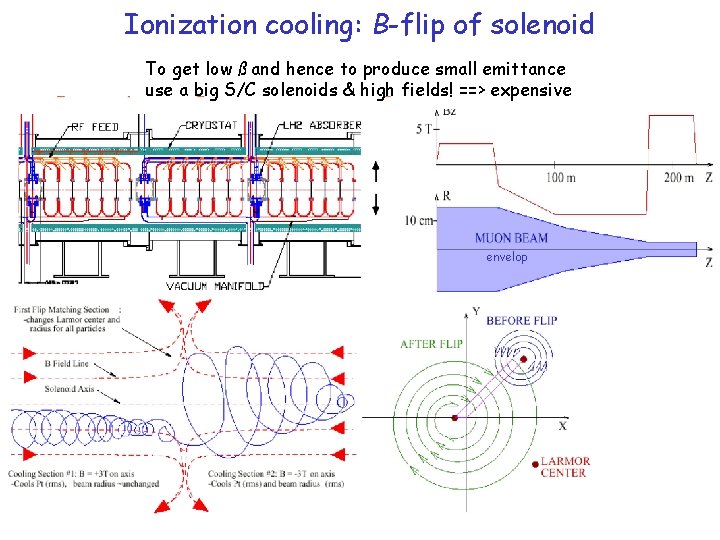
Ionization cooling: B-flip of solenoid To get low ß and hence to produce small emittance use a big S/C solenoids & high fields! ==> expensive envelop
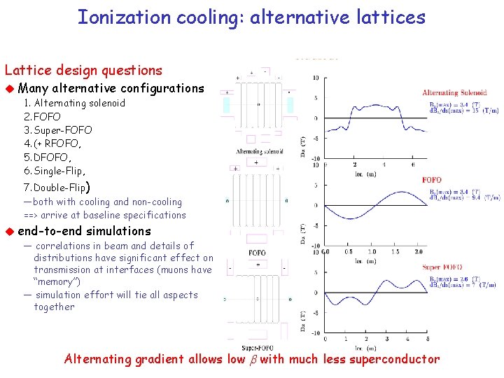
Ionization cooling: alternative lattices Lattice design questions Many alternative configurations 1. Alternating solenoid 2. FOFO 3. Super-FOFO 4. (+ RFOFO, 5. DFOFO, 6. Single-Flip, 7. Double-Flip) —both with cooling and non-cooling ==> arrive at baseline specifications end-to-end simulations — correlations in beam and details of distributions have significant effect on transmission at interfaces (muons have “memory”) — simulation effort will tie all aspects together Alternating gradient allows low b with much less superconductor
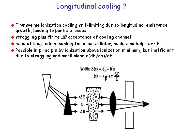
Longitudinal cooling ? Transverse ionization cooling self-limiting due to longitudinal emittance growth, leading to particle losses straggling plus finite E acceptance of cooling channel need of longitudinal cooling for muon collider; could also help for F Possible in principle by ionization above ionization minimum, but inefficient due to straggling and small slope d(d. E/ds)/d. E
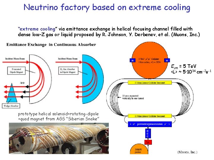
Neutrino factory based on extreme cooling “extreme cooling” via emittance exchange in helical focusing channel filled with dense low-Z gas or liquid proposed by R. Johnson, Y. Derbenev, et al. (Muons, Inc. ) Ecm = 5 Te. V <L> ~ 5· 1034 cm-2 s-1 prototype helical solenoid+rotating-dipole +quad magnet from AGS “Siberian Snake”
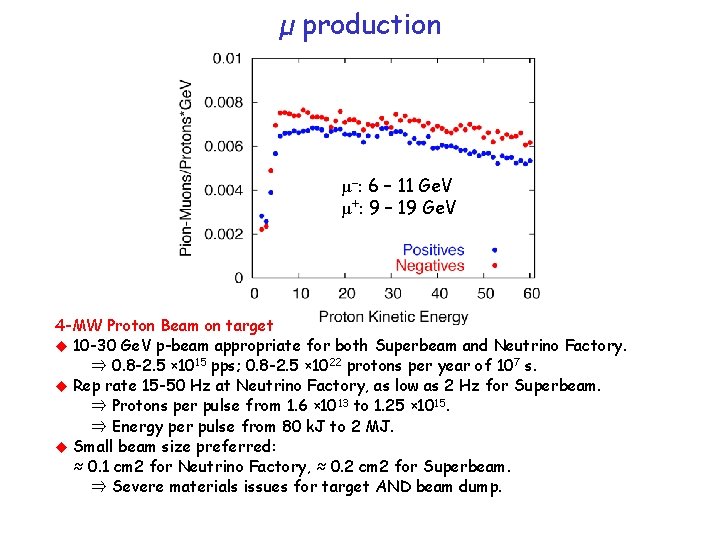
µ production µ–: 6 – 11 Ge. V µ+: 9 – 19 Ge. V 4 -MW Proton Beam on target 10 -30 Ge. V p-beam appropriate for both Superbeam and Neutrino Factory. ⇒ 0. 8 -2. 5 × 10¹⁵ pps; 0. 8 -2. 5 × 10²² protons per year of 107 s. Rep rate 15 -50 Hz at Neutrino Factory, as low as 2 Hz for Superbeam. ⇒ Protons per pulse from 1. 6 × 10¹³ to 1. 25 × 1015. ⇒ Energy per pulse from 80 k. J to 2 MJ. Small beam size preferred: ≈ 0. 1 cm 2 for Neutrino Factory, ≈ 0. 2 cm 2 for Superbeam. ⇒ Severe materials issues for target AND beam dump.
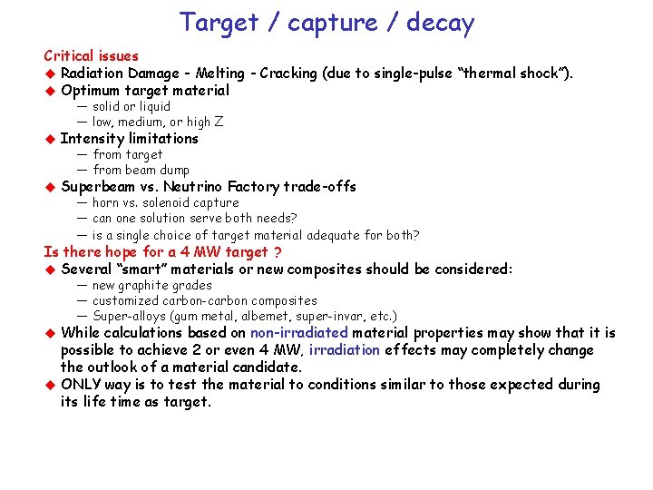
Target / capture / decay Critical issues Radiation Damage - Melting - Cracking (due to single-pulse “thermal shock”). Optimum target material — solid or liquid — low, medium, or high Z Intensity limitations Superbeam vs. Neutrino Factory trade-offs — from target — from beam dump — horn vs. solenoid capture — can one solution serve both needs? — is a single choice of target material adequate for both? Is there hope for a 4 MW target ? Several “smart” materials or new composites should be considered: — new graphite grades — customized carbon-carbon composites — Super-alloys (gum metal, albemet, super-invar, etc. ) While calculations based on non-irradiated material properties may show that it is possible to achieve 2 or even 4 MW, irradiation effects may completely change the outlook of a material candidate. ONLY way is to test the material to conditions similar to those expected during its life time as target.
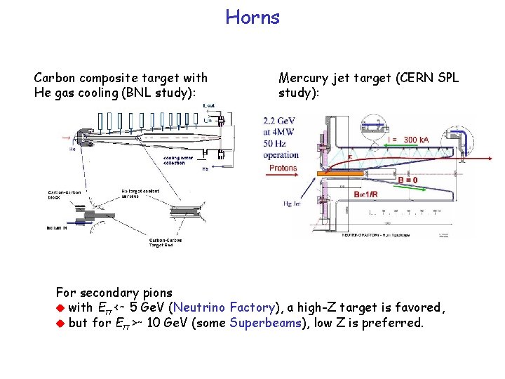
Horns Carbon composite target with He gas cooling (BNL study): Mercury jet target (CERN SPL study): For secondary pions with Eπ <∼ 5 Ge. V (Neutrino Factory), a high-Z target is favored, but for Eπ >∼ 10 Ge. V (some Superbeams), low Z is preferred.
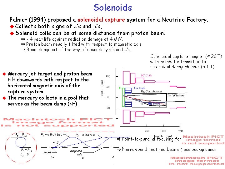
Solenoids Palmer (1994) proposed a solenoidal capture system for a Neutrino Factory. Collects both signs of p’s and m’s, Solenoid coils can be at some distance from proton beam. ⇒ ≥ 4 year life against radiation damage at 4 MW. ⇒ Proton beam readily tilted with respect to magnetic axis. ⇒ Beam dump out of the way of secondary p’s and m’s. Solenoidal capture magnet (≈ 20 T) with adiabatic transition to solenoidal decay channel (≈ 1 T). Mercury jet target and proton beam tilt downwards with respect to the horizontal magnetic axis of the capture system The mercury collects in a pool that serves as the beam dump ( F). ⇒ Point-to-parallel focusing for ⇒ Narrowband neutrino beams (less background)
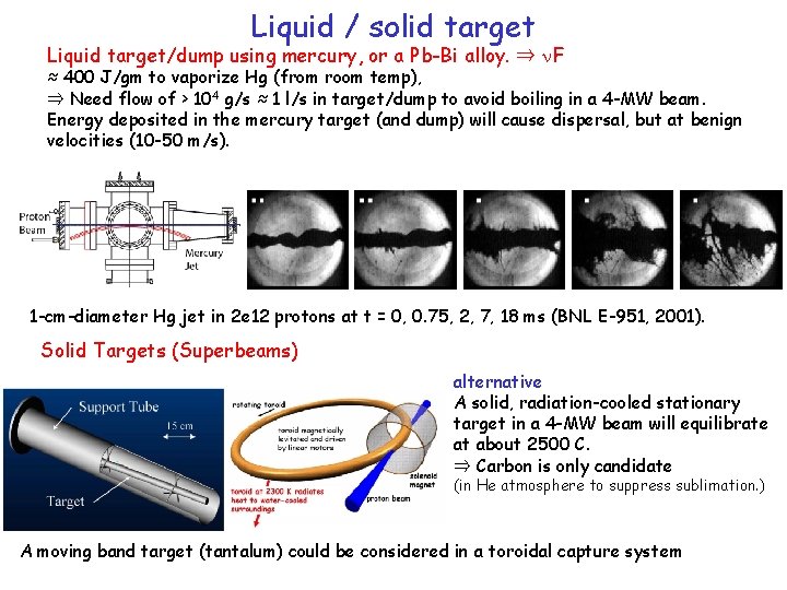
Liquid / solid target Liquid target/dump using mercury, or a Pb-Bi alloy. ⇒ F ≈ 400 J/gm to vaporize Hg (from room temp), ⇒ Need flow of > 104 g/s ≈ 1 l/s in target/dump to avoid boiling in a 4 -MW beam. Energy deposited in the mercury target (and dump) will cause dispersal, but at benign velocities (10 -50 m/s). 1 -cm-diameter Hg jet in 2 e 12 protons at t = 0, 0. 75, 2, 7, 18 ms (BNL E-951, 2001). Solid Targets (Superbeams) alternative A solid, radiation-cooled stationary target in a 4 -MW beam will equilibrate at about 2500 C. ⇒ Carbon is only candidate (in He atmosphere to suppress sublimation. ) A moving band target (tantalum) could be considered in a toroidal capture system
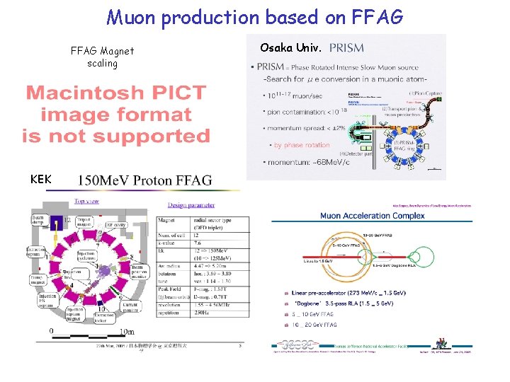
Muon production based on FFAG Magnet scaling KEK Osaka Univ.
Proton driver for a Neutrino Factory Proton Driver Questions Optimum beam energy — depends on choice of target ==> consider C, Ta, Hg Hardware options — FFAG, linac, synchrotron ==> compare performance, cost Beam dynamics – beam current limitations (injection, acceleration, activation) – bunch length limitations and schemes to provide 1 -3 ns bunches, approaches for bunch compression – repetition rate limitations (power, vacuum chamber, …) – tolerances (field errors, alignment, RF stability, …) Superbeam Factory versus Neutrino Factory requirements - required emittance and focusing - staging
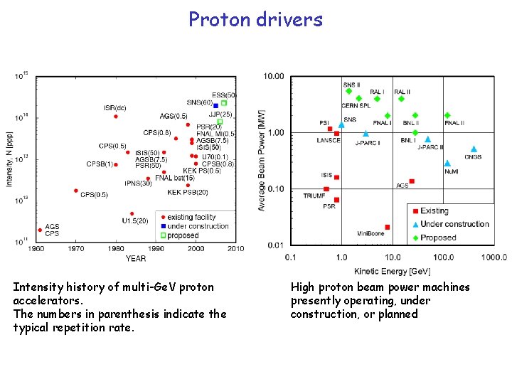
Proton drivers Intensity history of multi-Ge. V proton accelerators. The numbers in parenthesis indicate the typical repetition rate. High proton beam power machines presently operating, under construction, or planned
Existing and Proposed Proton Drivers The pulse structure is given in terms of the pulse duration tp, the number of bunches Nb making up each pulse, and the final compressed rms bunch length tb.
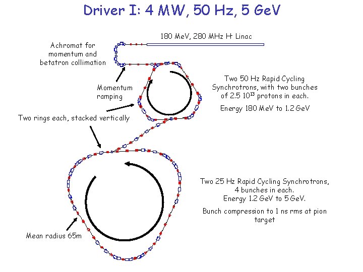
Driver I: 4 MW, 50 Hz, 5 Ge. V Achromat for momentum and betatron collimation Momentum ramping Two rings each, stacked vertically 180 Me. V, 280 MHz H- Linac Two 50 Hz Rapid Cycling Synchrotrons, with two bunches of 2. 5 1013 protons in each. Energy 180 Me. V to 1. 2 Ge. V Two 25 Hz Rapid Cycling Synchrotrons, 4 bunches in each. Energy 1. 2 Ge. V to 5 Ge. V. Bunch compression to 1 ns rms at pion target Mean radius 65 m
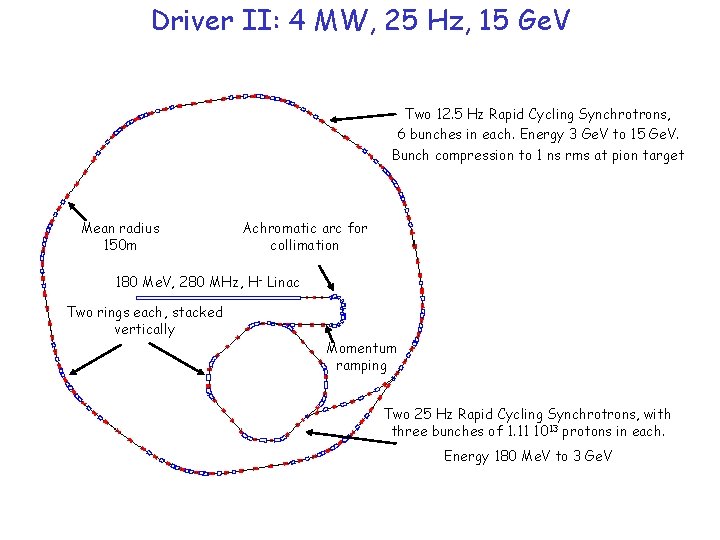
Driver II: 4 MW, 25 Hz, 15 Ge. V Two 12. 5 Hz Rapid Cycling Synchrotrons, 6 bunches in each. Energy 3 Ge. V to 15 Ge. V. Bunch compression to 1 ns rms at pion target Mean radius 150 m Achromatic arc for collimation 180 Me. V, 280 MHz, H- Linac Two rings each, stacked vertically Momentum ramping Two 25 Hz Rapid Cycling Synchrotrons, with three bunches of 1. 11 1013 protons in each. Energy 180 Me. V to 3 Ge. V
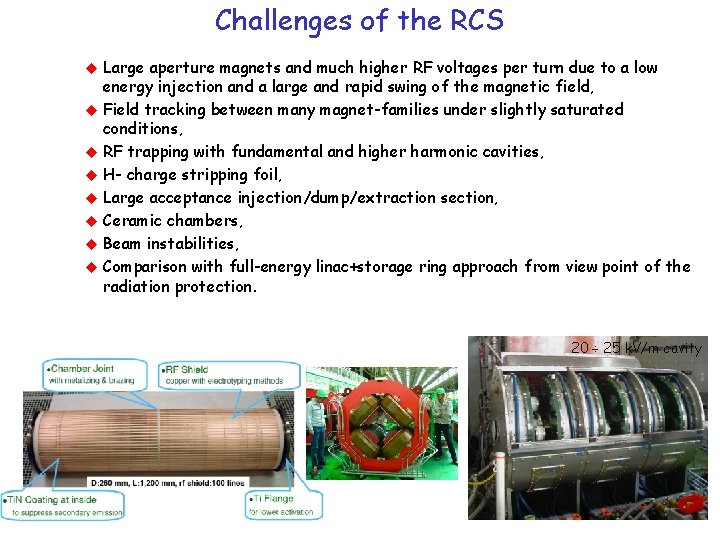
Challenges of the RCS Large aperture magnets and much higher RF voltages per turn due to a low energy injection and a large and rapid swing of the magnetic field, Field tracking between many magnet-families under slightly saturated conditions, RF trapping with fundamental and higher harmonic cavities, H- charge stripping foil, Large acceptance injection/dump/extraction section, Ceramic chambers, Beam instabilities, Comparison with full-energy linac+storage ring approach from view point of the radiation protection. 20 ÷ 25 k. V/m cavity
Other applications of Proton Drivers Type of accelerator Energy [Ge. V] duty factor DF Neutron for material studies • neutron yield proportional to beam power 0. 5 ÷ 10 CW ÷ 10 -4 Neutron spallation | nuclear waste transmutation | accelerator driven supercritical reactors • lower energy to limit the power deposition in the target window • higher energy up to full absorption of beam power in the reactor vessel 0. 5 ÷ 5 CW Kaons and heavy flavor • high DT to minimize the detector dead time • high energy to stay beyond production threshold > 20 0. 5 ÷ 1 Neutrino • low DF to minimize background from cosmic rays • energy tailored on wanted neutrino energy > 1 Ge. V 10 -5 Muons for neutrino factory • low DF to limit the up-time of muon cooling channel • high E to minimize the peak current (eg for 5 MW ==> Ipeak ~ 150 A) > 3 Ge. V 10 -5 Muons for muon colliders • low DF to minimize the muon bunch length (hence maximize the luminosity) • high E to minimize the peak current (eg for 5 MW ==> Ipeak ~ 2 k. A 20 ÷ 30 10 -7
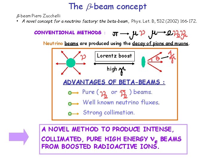
The b-beam concept b-beam Piero Zucchelli • A novel concept for a neutrino factory: the beta-beam, Phys. Let. B, 532 (2002) 166 -172. CONVENTIONAL METHODS : Neutrino beams are produced using the decay of pions and muons. Lorentz boost high ADVANTAGES OF BETA-BEAMS : Pure ( or ) beams. Well known neutrino fluxes. Strong collimation. A NOVEL METHOD TO PRODUCE INTENSE, COLLIMATED, PURE HIGH ENERGY ne BEAMS FROM BOOSTED RADIOACTIVE IONS.
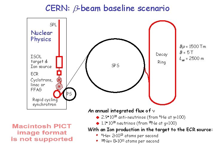
CERN: b-beam baseline scenario SPL Nuclear Physics Decay ISOL target & Ion source ECR Cyclotrons, linac or FFAG Rapid cycling synchrotron Ring SPS Br = 1500 Tm B=5 T Lss = 2500 m PS An annual integrated flux of 2. 9*1018 anti-neutrinos (from 6 He at g=100) 1. 1*1018 neutrinos (from 18 Ne at g=100) With an Ion production in the target to the ECR source: 6 He= 2*1013 atoms per second 18 Ne= 8 1011 atoms per second *
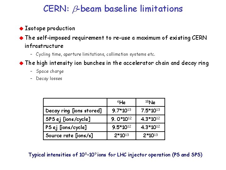
CERN: b-beam baseline limitations Isotope production The self-imposed requirement to re-use a maximum of existing CERN infrastructure – Cycling time, aperture limitations, collimation systems etc. The high intensity ion bunches in the accelerator chain and decay ring – Space charge – Decay losses 6 He 18 Ne Decay ring [ions stored] 9. 7*1013 7. 5*1013 SPS ej [ions/cycle] 9. 0*1012 4. 3*1012 PS ej [ions/cycle] 9. 5*1012 4. 3*1012 2*1013 Source rate [ions/s] Typical intensities of 108 -109 ions for LHC injector operation (PS and SPS)
Decay ring design aspects The ions have to be concentrated in a few very short bunches – Suppression of atmospheric background via time structure. There is an essential need for stacking in the decay ring – Not enough flux from source and injector chain. – Lifetime is an order of magnitude larger than injector cycling (120 s compared with 8 s SPS cycle). – Need to stack for at least 10 to 15 injector cycles. Cooling is not an option for the stacking process – Electron cooling is excluded because of the high electron beam energy and, in any case, the cooling time is far too long. – Stochastic cooling is excluded by the high bunch intensities. Stacking without cooling “conflicts” with Liouville
Lecture VI - neutrino projects reminder Neutrino physics is very appealing Neutrino beam devices are complex and expensive Superbeam is the basic initial block os a modern neutrino facility, it relies on the construction of a multimegawatt proton driver Muon accelerators are the next step and rely on a performing target system capture channel and on the very challenging ion cooling Neutrino factories and muon colliders are the last step (cost is matter Beta-beams are a clever shortcut