Introduction to Optical Fiber Cable Course Outline Introduction

Introduction to Optical Fiber Cable

Course Outline • Introduction • Applications and future development • Transmission to support broadband services • Trends and market in optical fiber technology

Introduction
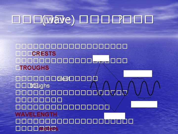
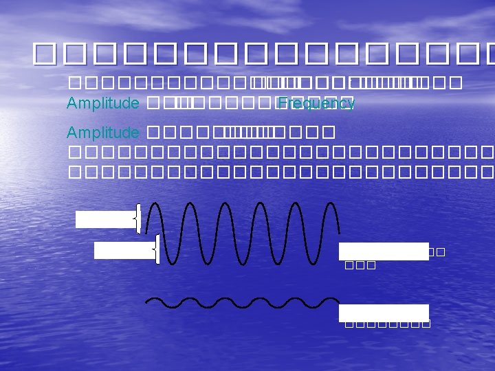
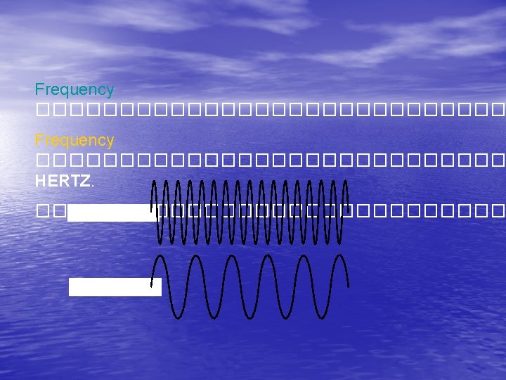

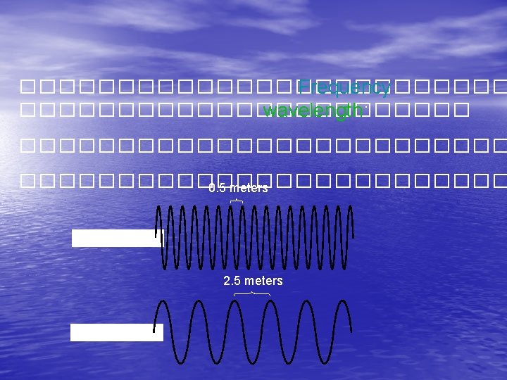
Period ���������������. Period ������������ frequency ����� periods 2 seconds ����. frequency ����� periods ���. HIGH FREQUENCY 10 seconds LOW FREQUENCY

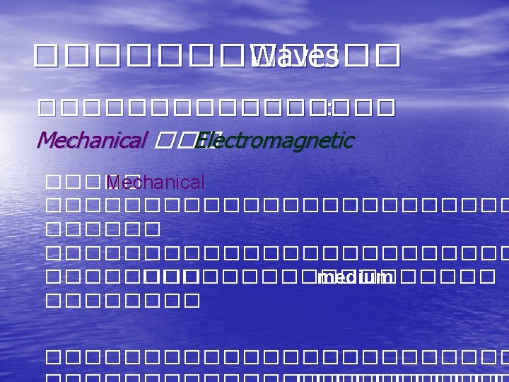
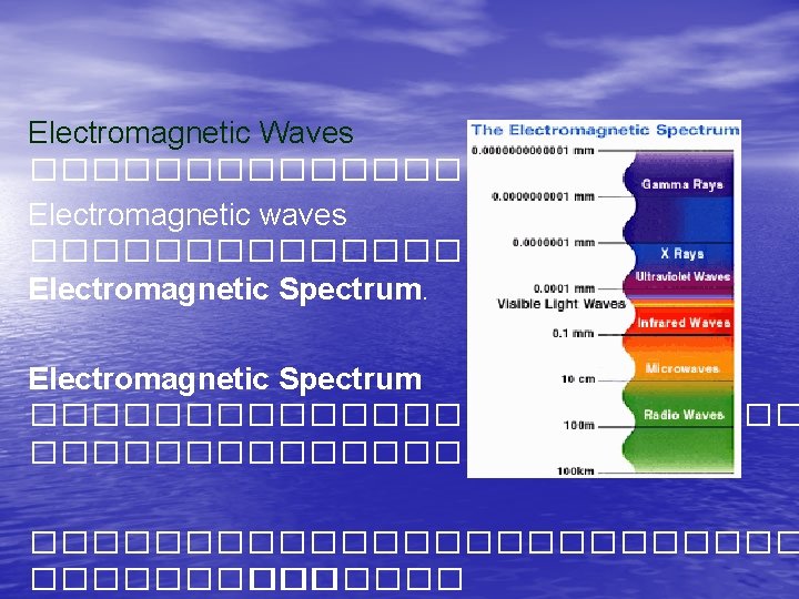


At the low energy end are the long wavelength Radio Waves. At the high energy end are the short wavelength Gamma Rays.


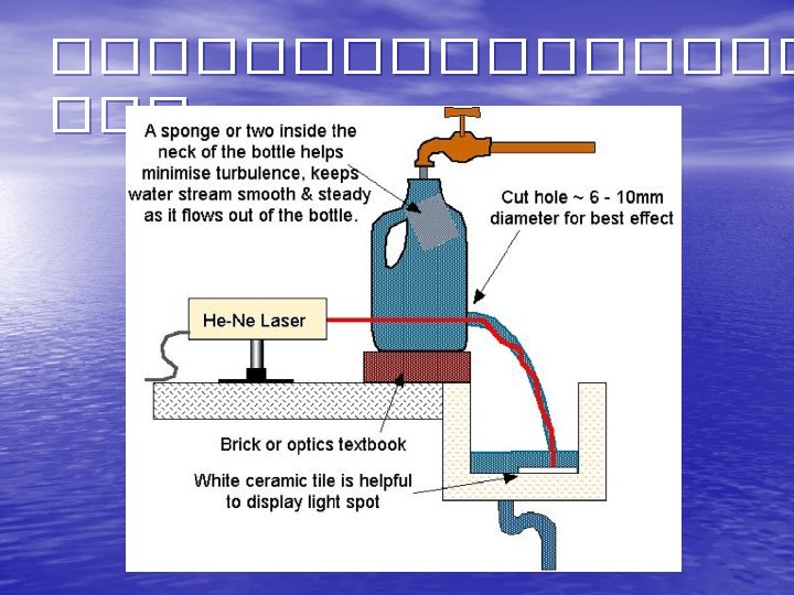

Optical Fiber Human hair for comparison 50 – 80 mm Typical refractive indices: Cladding: Core: ncl = 1. 4440 nco = 1. 4512 Light is guided along the core by Total Internal Reflection Cladding helps isolate light from edge of fibre where losses and scattering are high 1 mm = 1/1000000 m

Total Internal Reflection Rays striking an interface between two dielectrics from the higher index side are totally internally reflected if the refracted ray angle calculated from Snell’s Law would otherwise exceed 90˚. If n 1 = 1. 470 and n 2 =1. 475, say, then qcrit = 85. 28˚ within a fibre core

Bound rays vs Refracting Rays Bound rays zig-zag indefinitely along a fibre or waveguide Refracting rays decay rapidly as they propagate
 • �������������� • �������������� (light source) ������������ lightemitting diode (LED)")
Optical Transmission System (Overview) • �������������� • �������������� (light source) ������������ lightemitting diode (LED) ��� laser diode ���� (Attenuation) – 1970: 20 d. B/km with purified glass – Current: 0. 2 d. B/Km • AT&T first standardized transmission at DS 3 speed • (45 Mbps) with multimode fiber �������������� single-mode fiber �������������� multimode fiber ����� Optical Spectrum – 850 nm

Fiber Optic Technology Multimode fiber " Multiple paths" for the light to travel Single mode fiber "Single path" for the light to travel LED Laser Light Emitting Diode Core 50 or 62. 5 micron diameter Core 9 micron diameter Cladding 125 micron diameter Outer coating 250 micron diameter ����� telecom, CATV, Broadcast, ����� LAN ������� Data communciation For comparison purposes this is the relative size of a human hair ( @ 70 microns)

Fiber types SM Single-Mode MM-SI Multi-Mode Step Index MM-GI Multi-Mode Graded Index refractive index

Modes in Fiber

������ TRANSMITTER FIBER Performance + – ������ modulation ������ fiber

Light Emitting Diode (LED( – + Typical performance data Power in MM-fiber: Power in SM-fiber: Direct Modulation Bandwidth: 100 m. W 100 MHz
: Max: Direct Modulation Bandwidth: 5 -10 m. W")
Laser Typical performance Power (in fiber): Max: Direct Modulation Bandwidth: 5 -10 m. W 100 -300 m. W 1 -10 GHz

Photodiode detector Typical performance data Responsivity: Bandwidth: ~1 m. A / m. W 1 -20 GHz + –

Transmitter and Receiver optical fiber optical transmitter optical receiver • Light emitter ������������������� – LED (light emitting diode); ����������� (<1 Gbps), ������� multimode fiber – Laser diode • Light detector ��������� – PIN photodiode: ����� LED – Avalanche photodiode; ���� PIN

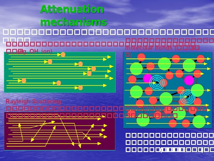
Attenuation
 ������������ dispersion ������������ bandwidth ����������� – Chromatic dispersion –")
Dispersion • Dispersion ������� (spreading) ������������ dispersion ������������ bandwidth ����������� – Chromatic dispersion – linear – Polarization Mode Dispersion (PMD) – nonlinear • Chromatic dispersion ������� wavelength ��������� bandwidth ������� 2. 5 Gbps – Material dispersion

Chromatic Dispersion Even if we eliminate all types of multimode dispersion, pulses of light having different wavelengths still travel at different velocities in silica, so pulse spreading is still possible if we use a spread of wavelengths. This is called Material Dispersion and is Together, Material Dispersion and responsible for rainbows etc. Waveguide Dispersion are termed Chromatic Dispersion. The pulse In the fundamental mode, the spread is proportional to fibre light spreads out differently into length L and wavelength spread Dl. the cladding depending on wavelength. Hence, different wavelengths have different ‘effective refractive indices’. This is Waveguide Dispersion.

Polarization Mode Dispersion (PMD( Ey nx Ex ny Pulse As It Enters the Fiber • pulse Spreaded Pulse As It Leaves the Fiber ������������ PMD ������ chromatic dispersion ������������ bit rates 10 Gb/s ������

Fiber performance z=0 z=L Attenuation z=0 z=L Dispersion

The 3 “R”s of Optical Networking A Light Pulse Propagating in a Fiber Experiences 3 Type of Degradations: Pulse as It Enters the Fiber Pulse as It Exits the Fiber Loss of Energy Shape Distortion Phase Variation Loss of Timing (Jitter) (From Various Sources) t ts Optimum Sampling Time
 The Options to Recover the Signal")
The 3 “R”s of Optical Networking (Cont. ) The Options to Recover the Signal from Attenuation/Dispersion/Jitter Degradation Are: Pulse as It Enters the Fiber Pulse as It Exits the Fiber Amplify to Boost the Power Re-Shape DCU Phase Variation Re-Generate Phase Re-Alignment O-E-O t ts Optimum Sampling Time Re-gen, Re-shape and ts Optimum Remove Optical Noise Sampling Time t
-transmission optical fiber optical receiver optical transmitter Multiwavelength Transmitter Multiwavelength Receiver")
WDM (wavelength division Multiplexing)-transmission optical fiber optical receiver optical transmitter Multiwavelength Transmitter Multiwavelength Receiver MUX DMX

Highway of Lights
 D » 2. 5 ps/nm-km")
Four Wave Mixing (FWM( True. Wave Fiber (50 km) D » 2. 5 ps/nm-km 1 nm 1. 5 nm 10 d. B/division 2 nm Dispersion-Shifted Fiber (25 km) D » 0 ps/nm-km 2 nm 1. 5 nm l 0 1546. 55 Wavelength (1 nm/division) Optical Launch Power = 3 d. Bm/channel

Characterizing Optical Sngals and Performance • BER ���� bit error rate • �������������� ������ – Noise – Intersymbol interference �������� – Interchannel interference �������� channel ������������ channel ������� bandwidth 2. 5 Gbps ����� 100 GHz – Nonlinear effects �������������� modulation ������

An optical communications link So, where does this optical fibre fit into the overall picture?
- Slides: 44