Introduction to MODIS design calibration and processing Modified

Introduction to MODIS design, calibration and processing Modified from PPT presented by Ewa Ainsworth (SAIC/NASA-GSFC)
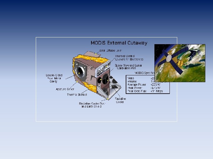

MODIS design and calibration SD – Solar Diffuser, primary source for the absolute radiometric calibration of VIS and NIR bands SDSM – Solar Diffuser Stability Monitor, alternately views the Sun through an attenuation screen and the light diffusely reflected from the SD and ratios the obtained radiances SRCA – Spectroradiometric Calibration Assembly SWIR – short-wave IR MWIR – medium-wave IR LWIR – long-wave IR FPA – Focal Plane Assembly
, two mirror")
Sensor characterization and calibration concerns • Mirror degradation, Response Versus Scan-angle (RVS), two mirror sides • Detector calibration changes • Polarization sensitivity • In-band out-of-band response • Instrument and focal plane temperature effects • Electronic cross-talk Solar Diffuser characterization • Stray-light contamination • Bi-directional Reflectance Factor (BRF) impact on calibration • Solar Diffuser stability Stray-light contamination • Photons in the optical path from Earth coming from bright sources, i. e. clouds, land, and sun glitter (characterized by point spread function) • • • Earth shine effect – sunlight reflecting off the Earth and onto the diffuser and adding to the solar irradiance Attenuation screen characterization through vignetting function SDSM uncertainty in monitoring SD reflectance changes

MODIS calibration stages • Direct calibration • Pre-launch – sensor is calibrated in a laboratory (thermal vacuum) • On-orbit – regular solar, deep-space, and lunar observations track changes in sensor response (possible additional on-board calibrators) • Absolute radiometric accuracy • reflective solar bands (0. 41 – 2. 1 m): ± 2% in reflectance and ± 5% in radiance • thermal emissive bands (3. 7 – 14. 4 m): ± 1% for most bands • Vicarious calibration – uses sources independent of the primary direct calibration – in situ measurements

MODIS-Aqua daily 1 August 2007 MODIS-Terra daily

MODIS data • Level 0 • ATT & EPH – spacecraft attitude – spacecraft position – raw digital counts – native binary format • GEO • Level 1 A – raw digital counts – HDF formatted – geolocation – radiant path geometry • Level 1 B – calibrated radiances – converted telemetry

Native satellite vs. map projection cylindrical isotropic projection increasing pixel size bow-tie effect
- Slides: 8