Introduction to Microcontrollers Learning Outcomes n Describe and

Introduction to Microcontrollers

Learning Outcomes n Describe and Identify the basic architecture of a digital computer, memory system, input/output devices, microprocessor and microcontroller interface, busses, typical control signals.

Outlines Microcontrollers and Embedded Processors n Overview of the 8051 family n

Revisions n Numbering and coding systems ¨ Decimal, binary, hexadecimal number systems / conversion ¨ Standard data codes : - ASCII n Digital primer ¨ Combinational Logic circuits and its operation (adder, decoder, multiplexer) Basics of a computer systems n Electronic parts (switch, LED, 7 -segment display) n

What is Microcontroller? Microcontroller is a small computer on a single integrated chip consisting of a central processing unit (CPU) or a microprocessor combined with peripheral devices such as memories (RAM, ROM), I/O devices and timers. n Application examples: - Remote controls, phones, printer, washing machine, traffic lights, etc. n

Example die shot of a microcontroller

Microcontroller and General-Purpose Microprocessor computer system that comprise many elements. A microprocessor cannot be operated stand-alone , at the very least it require some memory and an output device to be useful. General-purpose microprocessors • No RAM (Random Access Memory) • No ROM (Read-Only Memory) • No I/O ports Microcontroller • • • CPU (microprocessor) RAM (Random Access Memory) ROM (Read-Only Memory) I/O ports Timer ADC and other peripherals
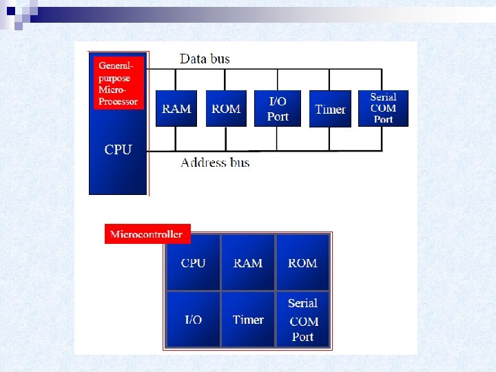

Microcontroller vs. General-Purpose Microprocessor General-purpose microprocessors • Must add RAM, ROM, I/O ports, and timers externally to make them functional • Make the system bulkier and much more expensive • Have the advantage of versatility on the amount of RAM, ROM, and I/O ports Microcontroller • The fixed amount of on-chip ROM, RAM, and number of I/O ports makes them ideal for many applications in which cost and space are critical • In many applications, the space it takes, the power it consumes, and the price per unit are much more critical considerations than the computing power
 to")
Microcontrollers for Embedded Systems n An embedded product uses a microprocessor (or microcontroller) to do one task and one task only ¨ n There is only one application software that is typically burned into ROM A PC, in contrast with the embedded system, can be used for any number of applications It has RAM memory and an operating system that loads a variety of applications into RAM and lets the CPU run them ¨ A PC contains or is connected to various embedded products ¨ Each one peripheral has a microcontroller inside it that performs only one task ¨

8051 Microcontroller n The 8051 is an 8 -bit processor ¨ The n CPU can work on only 8 bits of data at a time The 8051 had ¨ 128 bytes of RAM ¨ 4 K bytes of on-chip ROM ¨ Two 16 bit timers / counters ¨ One serial port ¨ Four I/O ports, each 8 bit wide ¨ 6 interrupt sources

8051 Microcontroller

8051 Memory Organization Two types of memory ¨ Program n permanently save the program being executed ¨ Data n Memory (ROM) Memory (RAM) temporarily storing data and intermediate results created and used during the operation of the microcontroller
 Register Bank • The lowest 32 bytes of the on-chip RAM")
Data Memory (RAM) Register Bank • The lowest 32 bytes of the on-chip RAM form 4 banks of 8 registers each. • Only one of these banks can be active at any time. • Bank is chosen by setting 2 bits in PSW – Default bank (at power up) is bank 0 (locations 00 – 07 h). • The 8 registers in any active bank are referred to as R 0 through R 7
 • The next 16 bytes – locations 20 H to 2")
Data Memory (RAM) • The next 16 bytes – locations 20 H to 2 FH – form a block that can be addressed as either bytes or individual bits. – The bytes have addresses 20 H to 2 FH. – The bits have addresses 00 H to 7 FH. – Specific instructions are used for accessing the bits. • Locations 30 H to 7 FH are general purpose RAM.
 Sort of control table used for running and monitoring the")
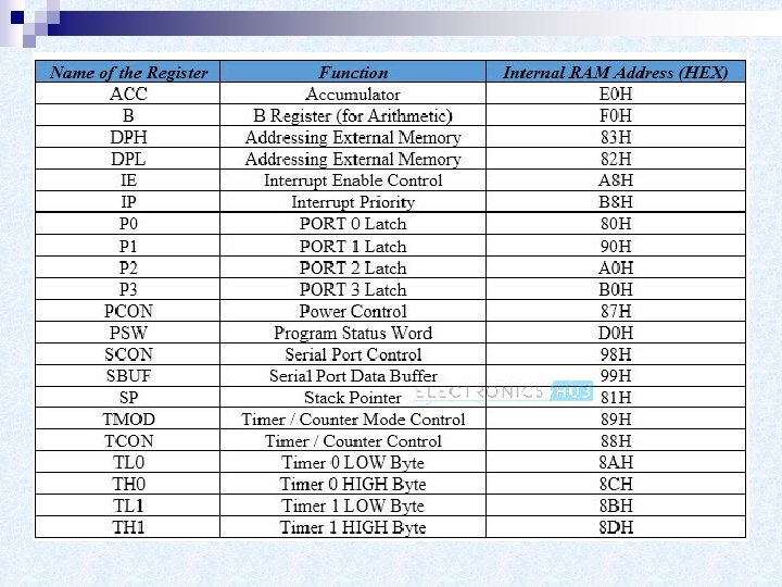
Special Function Registers (SFRs) Sort of control table used for running and monitoring the operation of the microcontroller. n Each of these registers as well as each bit they include, has its name, address in the scope of RAM and precisely defined purpose such as timer control, interrupt control, serial communication control etc. n
 n n n A general-purpose register used for storing intermediate results")
A Register (Accumulator) n n n A general-purpose register used for storing intermediate results obtained during operation. Prior to executing an instruction upon any number or operand it is necessary to store it in the accumulator first. All results obtained from arithmetical operations performed by the ALU are stored in the accumulator. Data to be moved from one register to another must go through the accumulator. A register is the most commonly used register and it is impossible to imagine a microcontroller without it. More than half instructions used by the 8051 microcontroller use somehow the accumulator.

B Register n Multiplication and division can be performed only upon numbers stored in the A and B registers. All other instructions in the program can use this register as a spare accumulator (A).
 Register PSW register is one of the most important SFRs.")
Program Status Word (PSW) Register PSW register is one of the most important SFRs. n It contains several status bits that reflect the current state of the CPU. Besides, this register contains Carry bit, Auxiliary Carry, two register bank select bits, Overflow flag, parity bit and user-definable status flag. n

n P - Parity bit. If a number stored in the accumulator is even this bit will be automatically set (1), otherwise it will be cleared (0). It is mainly used during data transmit and receive via serial communication. n - Bit 1. This bit is intended to be used in the future versions of microcontrollers. n OV Overflow occurs when the result of an arithmetical operation is larger than 255 and cannot be stored in one register. Overflow condition causes the OV bit to be set (1). Otherwise, it will be cleared (0).

n RS 0, RS 1 - Register bank select bits. These two bits are used to select one of four register banks of RAM. By setting and clearing these bits, registers R 0 -R 7 are stored in one of four banks of RAM. n F 0 - Flag 0. This is a general-purpose bit available for use. n AC - Auxiliary Carry Flag is used for BCD operations only. n CY - Carry Flag is the (ninth) auxiliary bit used for all arithmetical operations and shift instructions.
 n n n DPTR register is not a true one")
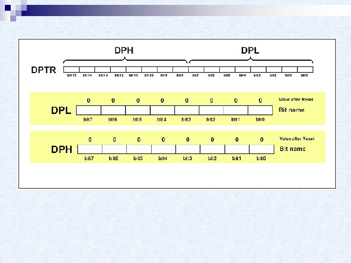
Data Pointer Register (DPTR) n n n DPTR register is not a true one because it doesn't physically exist. It consists of two separate registers: DPH (Data Pointer High) and (Data Pointer Low). For this reason it may be treated as a 16 -bit register or as two independent 8 -bit registers. Their 16 bits are primarily used for external memory addressing. Besides, the DPTR Register is usually used for storing data and intermediate results.
- Slides: 24