
Introduction to HVDC FACTS Power system stability Power

Introduction to HVDC FACTS Power system stability Power converters & Techniques Dr. N. M. JOTHI SWAROOPAN Prof/EEE RMK Engineering College, Chennai
History In the past. . . At the beginning of 20 th century, DC (Direct Current) was superseded by AC (Alternating Current) for large-scale electrification. DC power did nevertheless survive, in applications like electric traction and drives. Today. . . Today, bulk power systems are 3 -phase AC, while utilization is either 1 -phase or 3 -phase AC.
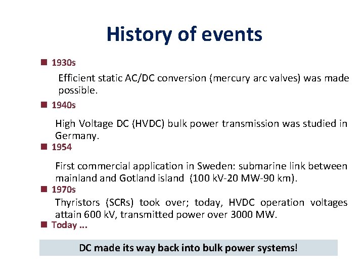
History of events 1930 s Efficient static AC/DC conversion (mercury arc valves) was made possible. 1940 s High Voltage DC (HVDC) bulk power transmission was studied in Germany. 1954 First commercial application in Sweden: submarine link between mainland Gotland island (100 k. V-20 MW-90 km). 1970 s Thyristors (SCRs) took over; today, HVDC operation voltages attain 600 k. V, transmitted power over 3000 MW. Today. . . DC made its way back into bulk power systems!
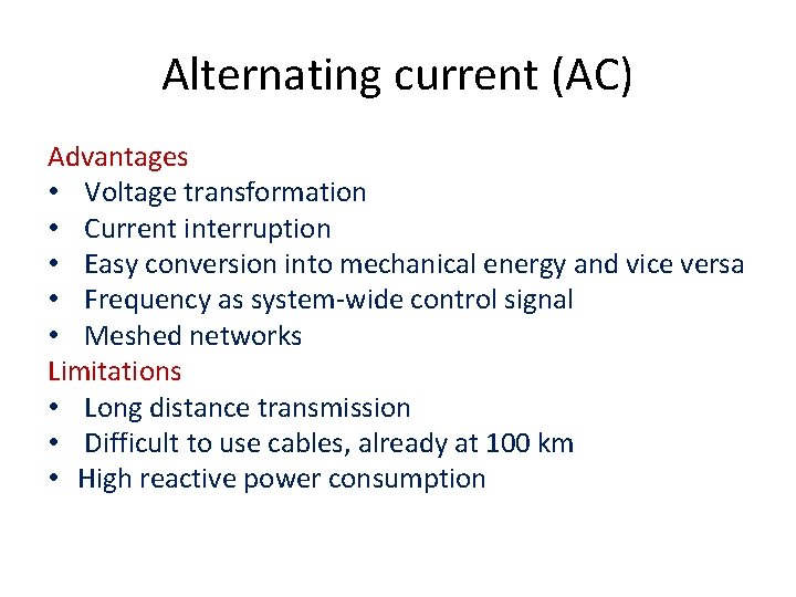
Alternating current (AC) Advantages • Voltage transformation • Current interruption • Easy conversion into mechanical energy and vice versa • Frequency as system-wide control signal • Meshed networks Limitations • Long distance transmission • Difficult to use cables, already at 100 km • High reactive power consumption
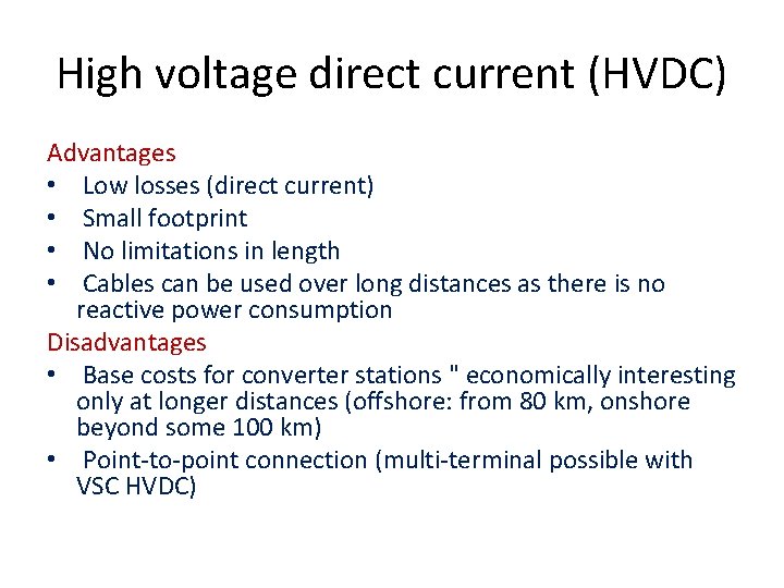
High voltage direct current (HVDC) Advantages • Low losses (direct current) • Small footprint • No limitations in length • Cables can be used over long distances as there is no reactive power consumption Disadvantages • Base costs for converter stations " economically interesting only at longer distances (offshore: from 80 km, onshore beyond some 100 km) • Point-to-point connection (multi-terminal possible with VSC HVDC)
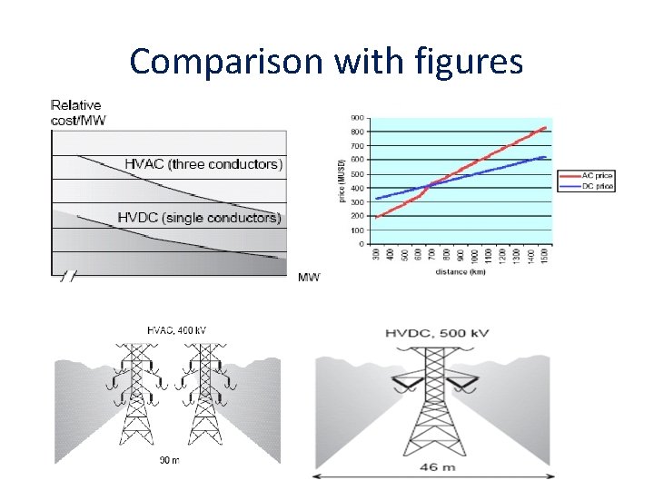
Comparison with figures
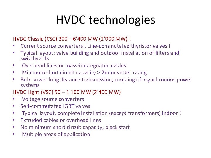
HVDC technologies HVDC Classic (CSC) 300 – 6’ 400 MW (2’ 000 MW) ! • Current source converters ! Line-commutated thyristor valves ! • Typical layout: valve building and outdoor installation of filters and switchyards • Overhead lines or mass-impregnated cables • Minimum short circuit capacity > 2 x converter rating • Bulk power long distance transmission, coupling of asynchronous power systems HVDC Light (VSC) 50 – 1’ 100 MW (2’ 400 MW) • Voltage source converters • Self-commutated IGBT valves • Typical layout. complete installation (except transformers) indoor ! • Extruded cables or overhead lines • No minimum short circuit capacity, black start • Multiple areas of application

Areas of application HVDC Classic (CSC) • Point to point transmission of bulk power over very long distances ! • Sea cables (> 100 km) • Connection of strong, asynchronous grids with high p HVDC Light (VSC) • Point to point transmission of small up to medium power over long distances • Connection of several (few) feed-in points, e. g. to support an existing AC grid • Suitable to be connected to weak grids or to supply passive loads (e. g. offshore platforms)
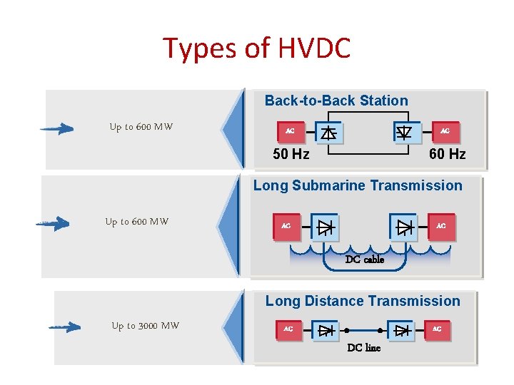
Types of HVDC Back-to-Back Station Up to 600 MW AC AC 50 Hz 60 Hz Long Submarine Transmission Up to 600 MW AC AC DC cable Long Distance Transmission Up to 3000 MW AC AC DC line

HVDC components
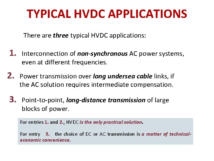
TYPICAL HVDC APPLICATIONS There are three typical HVDC applications: 1. Interconnection of non-synchronous AC power systems, even at different frequencies. 2. Power transmission over long undersea cable links, if the AC solution requires intermediate compensation. 3. Point-to-point, long-distance transmission of large blocks of power. For entries 1. and 2. , HVDC is the only practical solution. For entry 3. the choice of DC or AC transmission is a matter of technicaleconomic convenience.
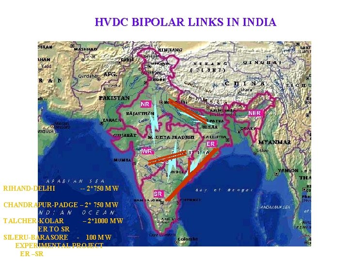
HVDC BIPOLAR LINKS IN INDIA NR NR NER ER ER RIHAND-DELHI -- 2*750 MW CHANDRAPUR-PADGE – 2* 750 MW TALCHER-KOLAR – 2*1000 MW ER TO SR SILERU-BARASORE - 100 MW EXPERIMENTAL PROJECT ER –SR SR SR
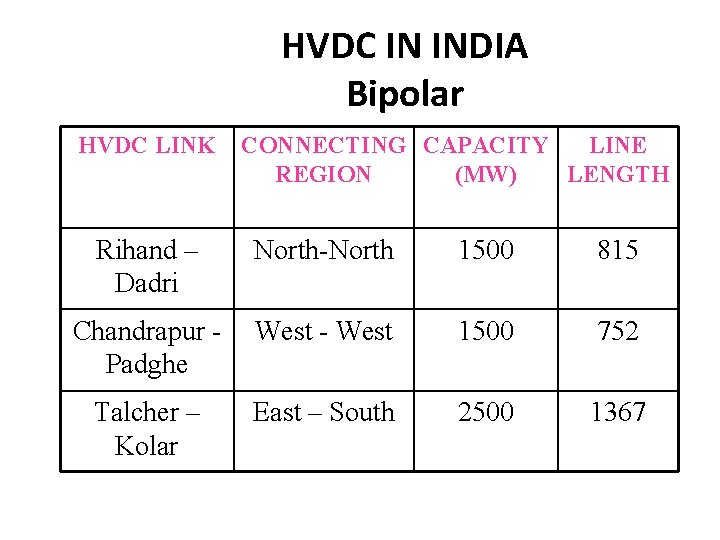
HVDC IN INDIA Bipolar HVDC LINK CONNECTING CAPACITY LINE REGION (MW) LENGTH Rihand – Dadri North-North 1500 815 Chandrapur Padghe West - West 1500 752 Talcher – Kolar East – South 2500 1367
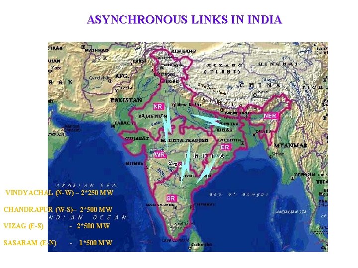
ASYNCHRONOUS LINKS IN INDIA NR NR NER ER ER VINDYACHAL (N-W) – 2*250 MW CHANDRAPUR (W-S)– 2*500 MW VIZAG (E-S) - 2*500 MW SASARAM (E-N) - 1*500 MW SR SR
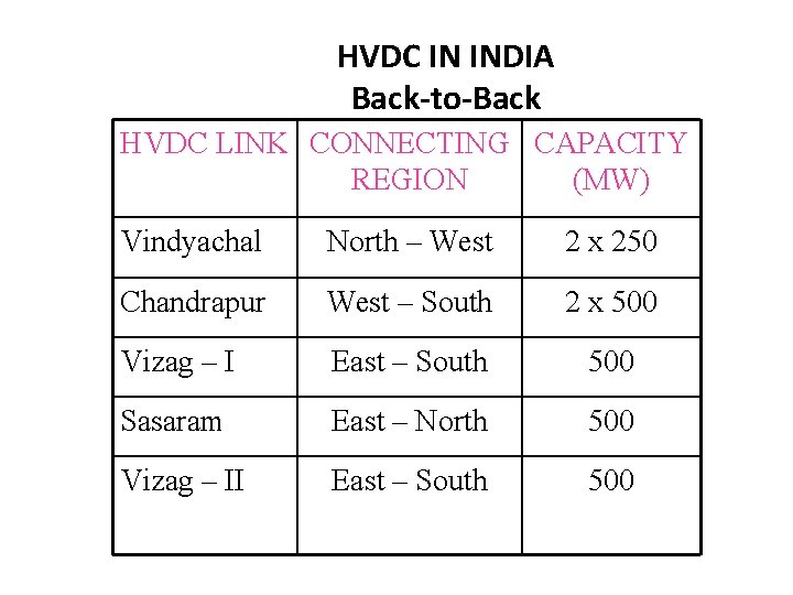
HVDC IN INDIA Back-to-Back HVDC LINK CONNECTING CAPACITY REGION (MW) Vindyachal North – West 2 x 250 Chandrapur West – South 2 x 500 Vizag – I East – South 500 Sasaram East – North 500 Vizag – II East – South 500
What is FACTS v Alternating current transmission systems incorporating power electronics-based and other static controllers to enhance controllability and increase power transfer capability
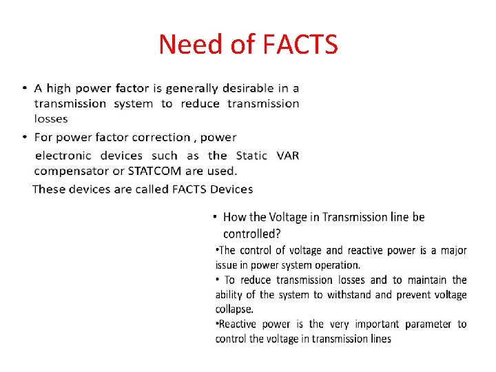
Need of FACTS
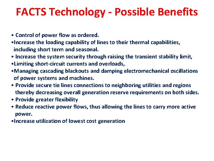
FACTS Technology - Possible Benefits • Control of power flow as ordered. • Increase the loading capability of lines to their thermal capabilities, including short term and seasonal. • Increase the system security through raising the transient stability limit, • Limiting short-circuit currents and overloads, • Managing cascading blackouts and damping electromechanical oscillations of power systems and machines. • Provide secure tie lines connections to neighboring utilities and regions thereby decreasing overall generation reserve requirements on both sides. • Provide greater flexibility • Reduce reactive power flows, thus allowing the lines to carry more active power. • Increase utilization of lowest cost generation
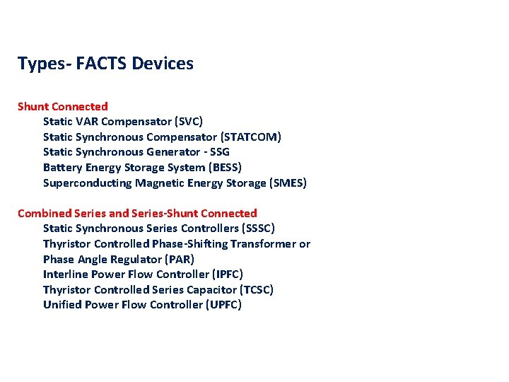
Types- FACTS Devices Shunt Connected Static VAR Compensator (SVC) Static Synchronous Compensator (STATCOM) Static Synchronous Generator - SSG Battery Energy Storage System (BESS) Superconducting Magnetic Energy Storage (SMES) Combined Series and Series-Shunt Connected Static Synchronous Series Controllers (SSSC) Thyristor Controlled Phase-Shifting Transformer or Phase Angle Regulator (PAR) Interline Power Flow Controller (IPFC) Thyristor Controlled Series Capacitor (TCSC) Unified Power Flow Controller (UPFC)
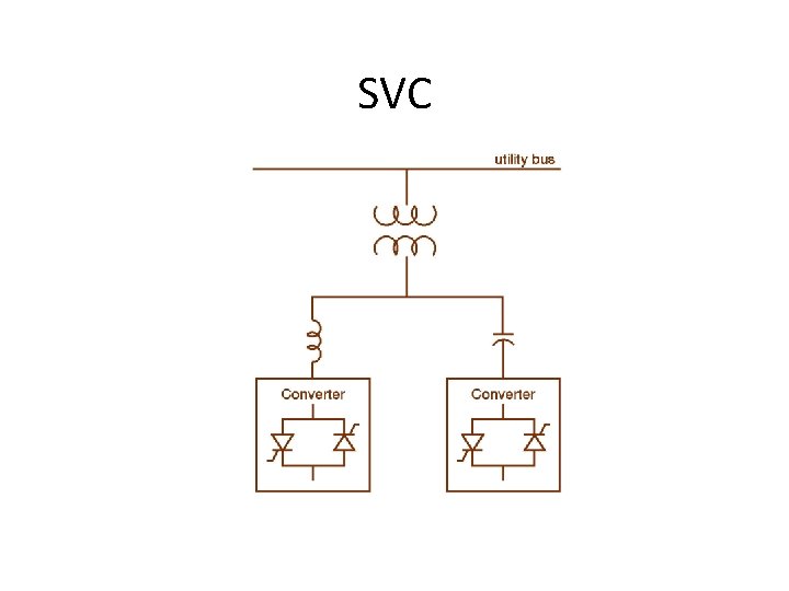
SVC
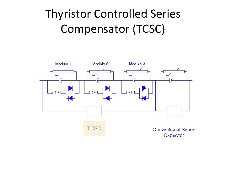
Thyristor Controlled Series Compensator (TCSC) TCSC
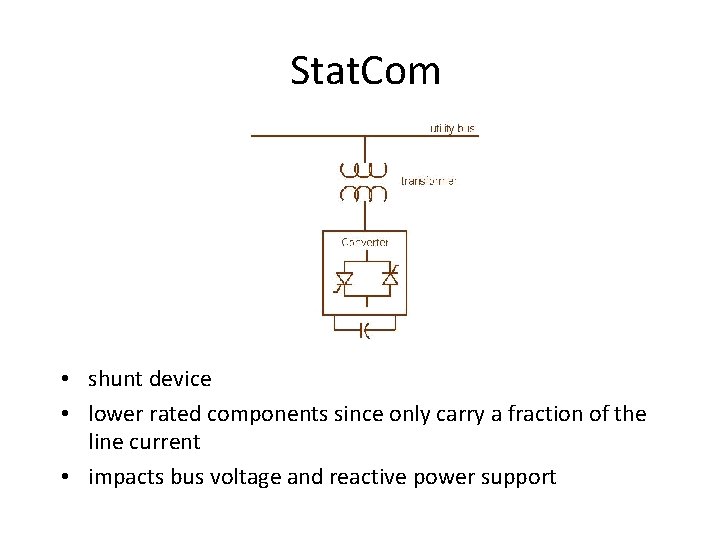
Stat. Com • shunt device • lower rated components since only carry a fraction of the line current • impacts bus voltage and reactive power support
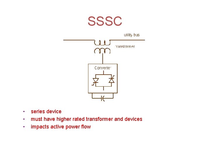
SSSC • • • series device must have higher rated transformer and devices impacts active power flow
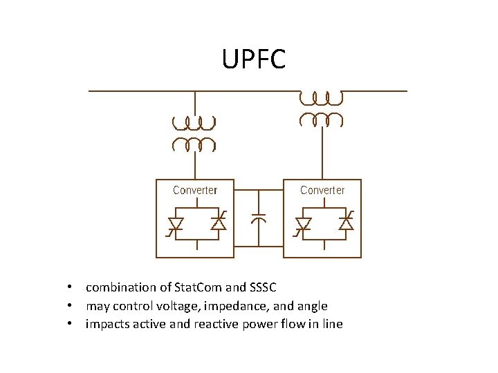
UPFC • combination of Stat. Com and SSSC • may control voltage, impedance, and angle • impacts active and reactive power flow in line
Devices used for FACTS Devices ØDiode (pn Junction) ØSilicon Controlled Rectifier (SCR) ØGate Turn-Off Thyristor (GTO) GE ØMOS Turn-Off Thyristor (MTO) SPCO ØEmitter Turn-Off Thyristor (ETO) Virginia Tech ØIntegrated Gate-Commutated Thyristor (IGCT) Mitsubishi, ABB ØMOS-Controlled Thyristor (MCT) Victor Temple ØInsulated Gate Bipolar Transistor (IGBT) IGBT has pushed out the conventional GTO as IGBTs ratings go up. IGBTs - Low-switching losses, fast switching, current-limiting capability GTOs - large gate-drive requirements, slow-switching, high-switching losses IGBTs (higher forward voltage drop)
Decision-Making Matrix
Voltage Source Vs. Current Source Converters
What is power system stability • Power system stability is an ability of an electric power system for a given initial operating condition , to regain a state of operating equilibrium after being subjected to a physical disturbance with all system variables are bounded.
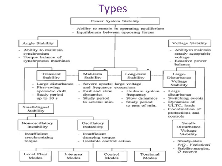
Types
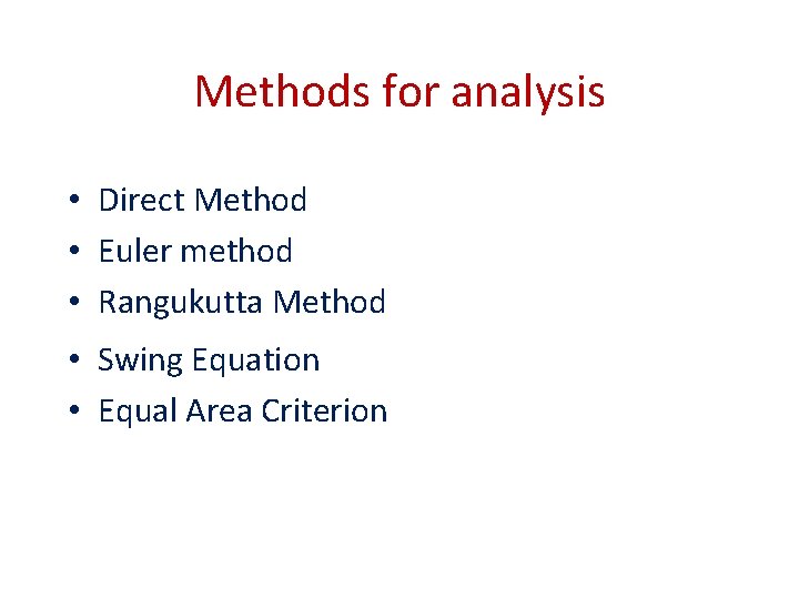
Methods for analysis • Direct Method • Euler method • Rangukutta Method • Swing Equation • Equal Area Criterion
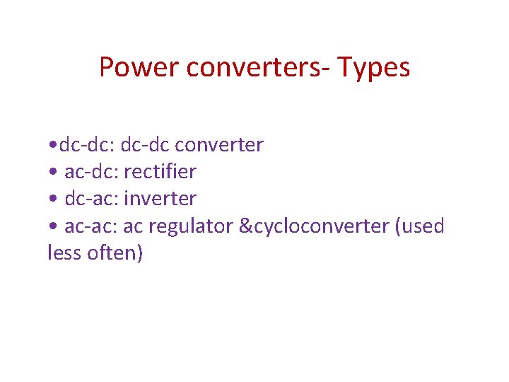
Power converters- Types • dc-dc: dc-dc converter • ac-dc: rectifier • dc-ac: inverter • ac-ac: ac regulator &cycloconverter (used less often)
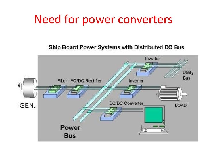
Need for power converters
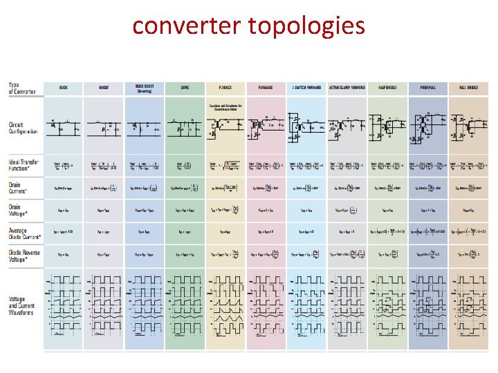
converter topologies
DC-DC Control Strategies (a)Time-ratio control • constant frequency operation • variable frequency operation (a)Current limit control.
- Slides: 37