Introduction to Gas Turbines Gas Turbines have been

Introduction to Gas Turbines • Gas Turbines have been used for electricity generation. • Gas turbines are ideal for ideal this application as they can be started and stopped quickly. • There are two basic types of gas turbines 1. Aero-derivative 2. Industrial Over the last ten years there have been major improvements to the sizes and efficiencies of the gas turbines

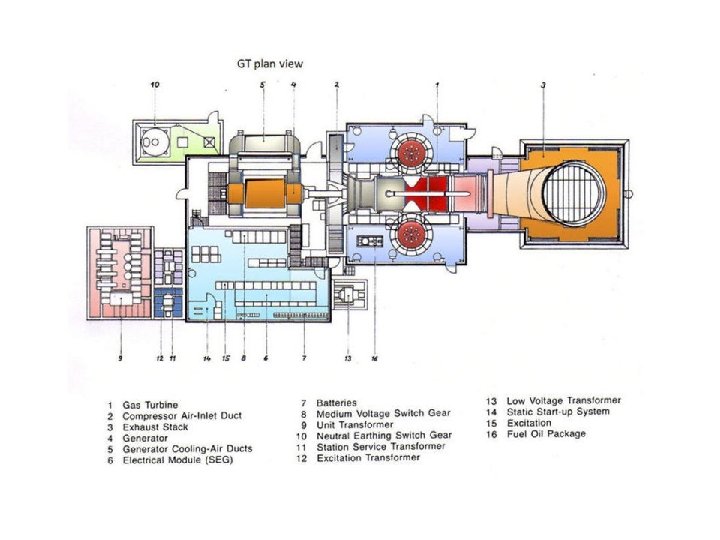
Layout gas turbine power plant

How does a Gas Turbine Work? Gas turbines use the hot gas produced by burning a fuel to drive a turbine. They are also called combustion turbines or combustion gas turbines. Because some of its heat and pressure energy has been transferred to the turbine, the gas is cooled to a lower pressure when it leaves the turbine. It is then either discharged up a chimney (often called a stack) or is directed to a special type of boiler, called a Heat Recovery Steam Generator (HRSG), where most of the remaining heat energy in the gas is used to produce steam.

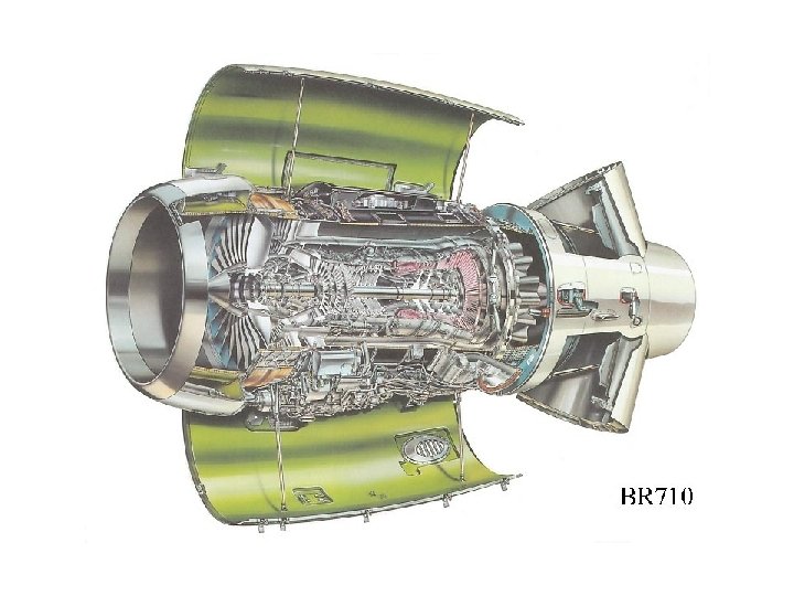
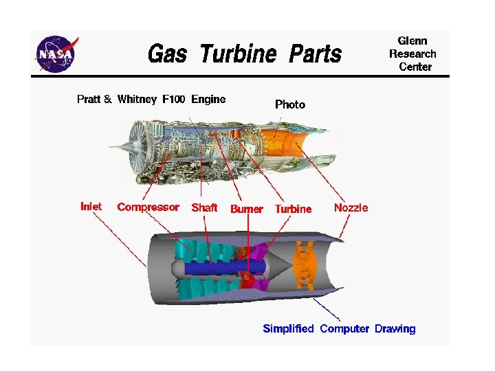
MODEL DESIGN The cross section of a typical large gas turbine

Air Compressor The air compressors used in gas turbines are made up of several rows of blades (similar to the blades on a household fan). Each row of blades compress and push the air onto the next row of blades. As the air becomes more and more compressed, the sizes of the blades become smaller from row to row. The row of largest blades can be seen at the left end of the compressor in the photo above, with the smallest blades to the right (the direction of air flow is from left to right). Note: A row of blades fixed to the outer casing of the compressor is also located after each row of moving blades

Fuel Gas turbines can operate on a variety of gaseous or liquid fuels, including: Liquid or gaseous fossil fuel such as crude oil, heavy fuel oil, natural gas, methane, distillate and "jet fuel" (a type of kerosene used in aircraft jet engines); Gas produced by gasification processes using, for example, coal, municipal waste and biomass; and Gas produced as a by-product of an industrial process such as oil refining. When natural gas is used, power output and thermal efficiency of the gas turbines are higher than when using most liquid fuels.

Inlet Air The air coming into the compressor of a gas turbine must be cleaned of impurities (such as dust and smoke) which could erode or stick to the blades of the compressor or turbine, reducing the power and efficiency of the gas turbine. Dry filters or water baths are usually used to carry out this cleaning.

Burners and Combustors The compressed air and fuel is mixed and metered in special equipment called burners. The burners are attached to chambers called combustors. The fuel & air mixture is ignited close to the exit tip of the burners, then allowed to fully burn in the combustors. The temperature of the gas in the combustors and entering the turbine can reach up to 1350°C. Special heat resistant materials (such as ceramics) are used to line the inside walls of the combustors. The area between the combustors and the turbine are also lined.
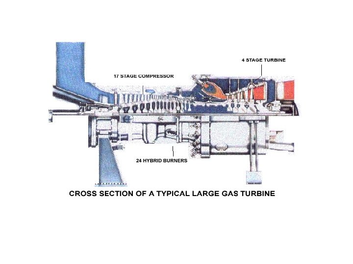
 enters the compressor at the left. The exhaust gas (red)")
The inlet air (blue) enters the compressor at the left. The exhaust gas (red) leaves the turbine at the right. The burners and combustors are located between the compressor and turbine. Gas turbines are very compact and occupy small ground area. . Silencers are usually fitted in the inlet air and exhaust gas ducts.

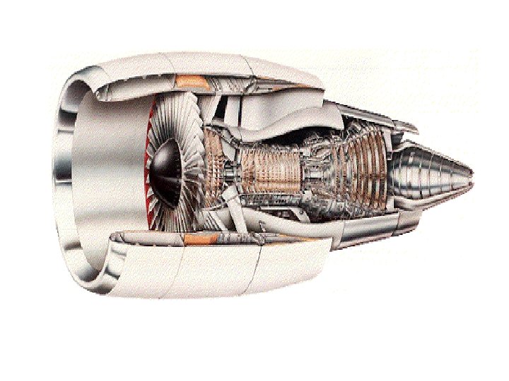
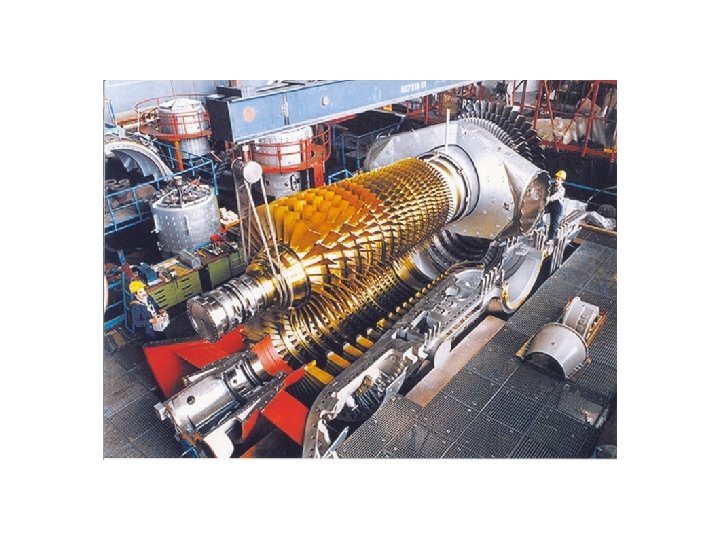
Gas Turbine with half case

The photo shows what such a gas turbine looks like when its top half casing has been removed for inspection or maintenance. The air compressor is on the left and the turbine is on the right. The section that would hold the burners and combustors is between the compressor and the turbine. Note the large bolts that are used to hold the two halves of the casing together.

Gas Turbines

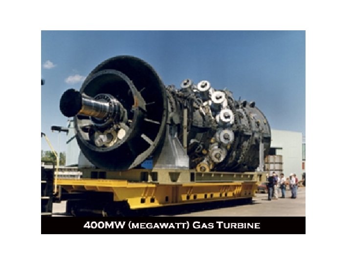
• Gas turbines are an established technology available in sizes ranging from several hundred kilowatts to over several hundred megawatts. Gas turbines produce high quality heat that can be used for industrial or district heating steam requirements. Alternatively, this high temperature heat can be recuperated to improve the efficiency of power generation or used to generate steam and drive a steam turbine in a combined-cycle plant. • Gas turbine emissions can be controlled to very low levels using dry combustion techniques, water or steam injection, or exhaust treatment. • Maintenance costs per unit of power output are about a third to a half of reciprocating engine generators. Low maintenance and high quality waste heat often make gas turbines favarable.

Half compressor
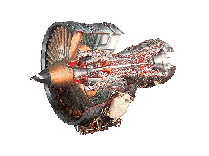
 turbines being installed in many of today's natural-gas-fueled power plants are")
The combustion (gas) turbines being installed in many of today's natural-gas-fueled power plants are complex machines, but they basically involve three main sections: The compressor which draws air into the engine, pressurizes it, and feeds it to the combustion chamber literally at speeds of hundreds of miles per hour.
 + ( Two isentropic processes) Two")
Both Rankine and Brayton Cycles (Two isobaric processes) + ( Two isentropic processes) Two phase: Rankine cycle – Steam Power Plant Single phase: Brayton cycles – Gas Turbine
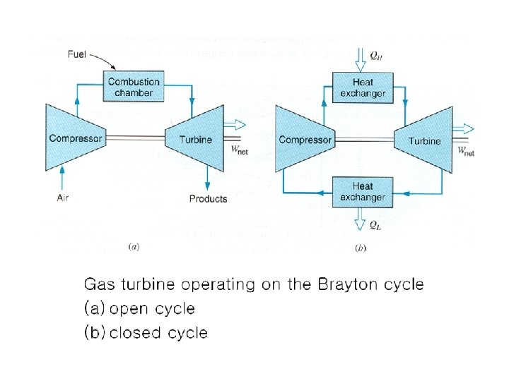

Air-standard Brayton cycle

Cycle efficiency as a function of pressure ratio for Brayton and regenerative Brayton cycles

Example In an air-standard Brayton cycle the air enters the compressor at 0. 1 MPa, 15 C. The pressure leaving the compressor is 1. 0 MPa, and the maximum temperature in the cycle is 1000 C. Determine 1. The pressure and temperature at each point in the cycle 2. The compressor work, turbine work, and cycle efficiency

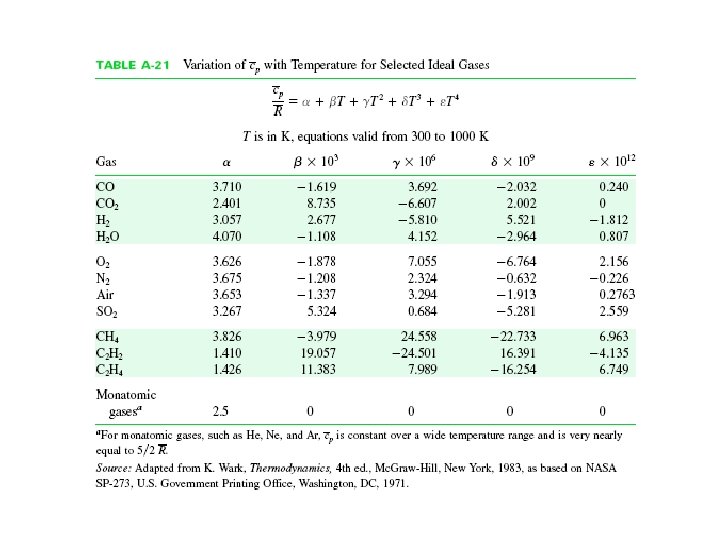
For each of the control volumes analyzed, the model is ideal gas with constant specific heat, value at 300 K, and each process is SSSF with no kinetic or potential energy changes. Control volume: Compressor. Inlet state: P 1, T 1 known; state fixed. Exit state: P 2 known.

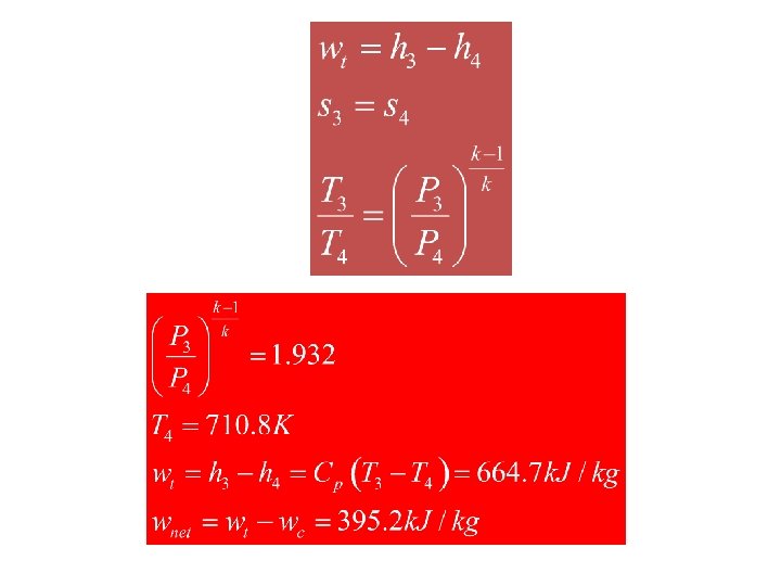
Control volume: Turbine. Inlet state: P 3, T 3 known; state fixed. Exit state: P 4 known.

Control volume: High-temperature heat exchange. Inlet state: state 2 fixed. Exit state: State 3 fixed. Control volume: Low-temperature heat exchange. Inlet state: state 4 fixed. Exit state: State 1 fixed.

Brayton Cycle In an actual gas turbine the max. temperature of the gas entering the turbine is fixed by material considerations. Large amount of compressor work vs that of turbine work (40~80%) -> due to difference in specific volumes cf. Rankine cycle (1~2% for pumping work)

Regeneration and Reheating in Brayton Cycle Gas Turbine Cycle with a Regenerator Ideal regenerative cycle

In general For an ideal regenerator In contrast to the Brayton cycle efficiency decreases with an increase in the pressure ratio for the cycle with a regenerator.

Efficiency of a Regenerator T-s diagram to illustrate definition of the regenerator efficiency

Ideal gas-turbine cycle using multistage compression with intercooling, multistage expansion with reheating, and a regenerator Reversible Adiabatic Process (Compressor, Turbine) -> Reversible Isothermal Process (Ericsson Cycle)

Ideal gas-turbine cycle utilizing intercooling, reheat and a regenerator

Multistage Compression with Intercooling Multistage Expansion with Reheating T-s diagram that shows how the gas-turbine cycle with many stages approaches the Ericsson cycle

Jet Propulsion Cycle Air-Standard Cycle for Jet Propulsion Ideal gas-turbine for a jet engine (Brayton cycle)+(Reversible adiabatic nozzle)

Example 2 Consider an ideal jet propulsion cycle in which air enters the compressor at 0. 1 MPa, 15 C. The pressure leaving the compressor is 1. 0 MPa, and the maximum temperature is 1100 C. The air expands in the turbine to a pressure at which the turbine work is just equal to the compressor work. On leaving the turbine, the air expands in a nozzle to 0. 1 MPa. The process is reversible and adiabatic. Determine the velocity of the air leaving the nozzle. The model used is ideal gas, constant specific heat, value at 300 K, and each process is SSSF with no potential energy change. The only kinetic energy change occurs in the nozzle.


Control volume: Nozzle. Inlet state: State 4 fixed. Exit state: P 5 known.

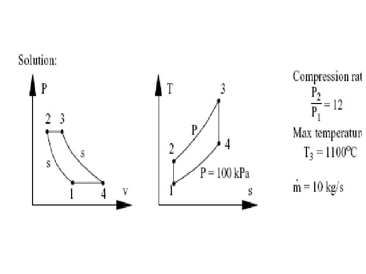
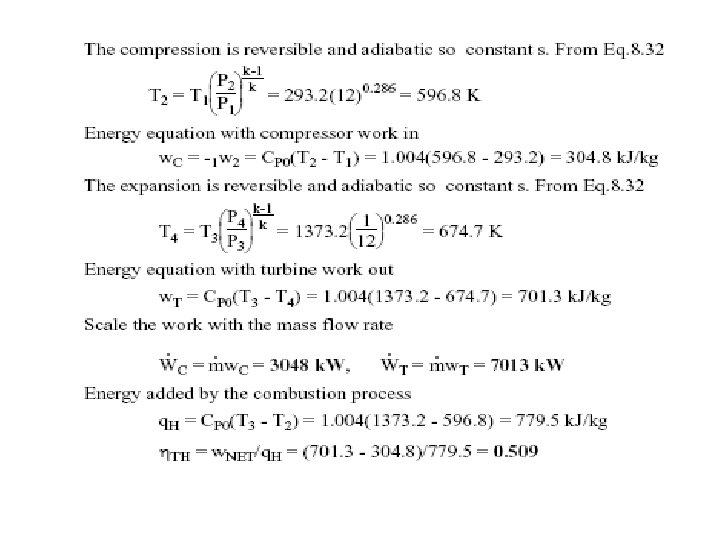
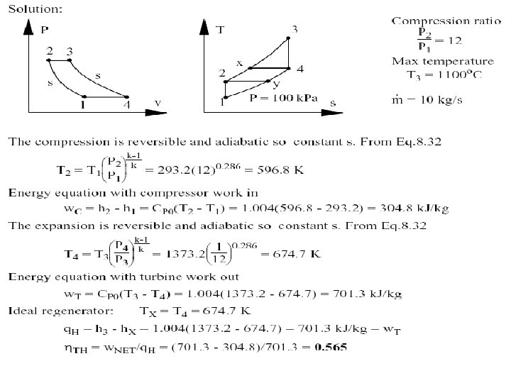
Example: 2. 1 Consider an ideal air-standard Brayton cycle in which the air into the compressor is at 100 k. Pa, 20°C, and the pressure ratio across the compressor is 12: 1. The maximum temperature in the cycle is 1100°C, and the air flow rate is 10 kg/s. Assume constant specific heat for the air, value from Table A. 5. Determine the compressor work, the turbine work, and thermal efficiency of the cycle.

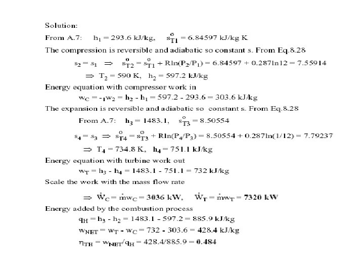
Example 2 -3 Repeat Example 2 -1, but assume variable specific heat for the air, table A. 7. Consider an ideal airstandard Brayton cycle in which the air into the compressor is at 100 k. Pa, 20°C, and the pressure ratio across the compressor is 12: 1. The maximum temperature in the cycle is 1100 o. C, and the air flow rate is 10 kg/s. Assume constant specific heat for the air, value from Table A. 5. Determine the compressor work, the turbine work, and thermal efficiency of the cycle.

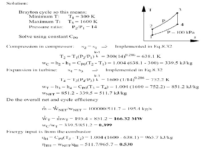
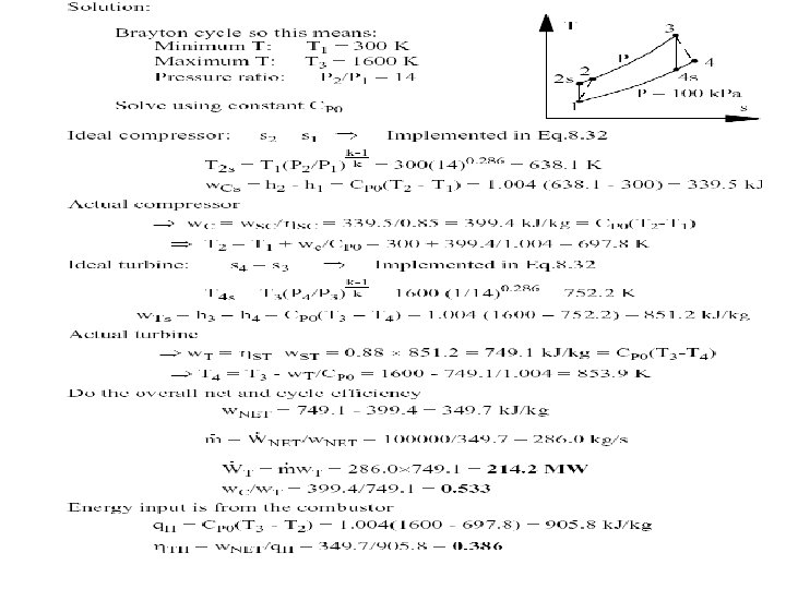
Example 2 -4 A large stationary Brayton cycle gas-turbine power plant delivers a power output of 100 MW to an electric generator. The minimum temperature in the cycle is 300 K, and the maximum temperature is 1600 K. The minimum pressure in the cycle is 100 k. Pa, and the compressor pressure ratio is 14 to 1. Calculate the power output of the turbine. What fraction of the turbine output is required to drive the compressor? What is thermal efficiency of the cycle?

Example 2 -5 An ideal regenerator is incorporated into the ideal airstandard Brayton cycle of Example 2 -1. Find thermal efficiency of the cycle with this modification. Consider an ideal air-standard Brayton cycle in which the air into the compressor is at 100 k. Pa, 20°C, and the pressure ratio across the compressor is 12: 1. The maximum temperature in the cycle is 1100°C, and the air flow rate is 10 kg/s. Assume constant specific heat for the air, value from Table A. 5. Determine the compressor work, the turbine work, and thermal efficiency of the cycle.

Example 2 -6 Repeat Example 2 -3, but include a regenerator with 75% efficiency in the cycle. A large stationary Brayton cycle gas-turbine power plant delivers a power output of 100 MW to an electric generator. The minimum temperature in the cycle is 300 K, and the maximum temperature is 1600 K. The minimum pressure in the cycle is 100 k. Pa, and the compressor pressure ratio is 14 to 1. Calculate the power output of the turbine. What fraction of the turbine output is required to drive the compressor? What is thermal efficiency of the cycle?


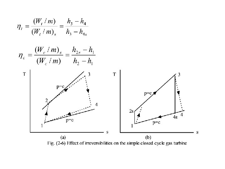
Example 2 -7 Repeat Example 2 -6, but assume that the compressor has an isentropic efficiency of 85% and the turbine an isentropic efficiency of 88%.

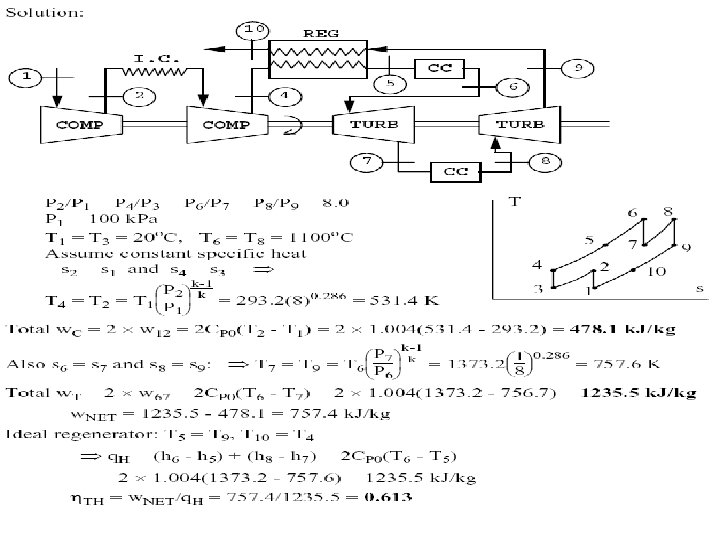
EXAMPLE 2. 8 A regenerative gas turbine with intercooling and reheat operates at steady state. Air enters the compressor at 100 k. Pa, 300 K with a mass flow rate of 5. 807 kg/s. The pressure ratio across the two stage compressor is 10. The pressure ratio across the two stage turbine is also 10. The intercooler and reheater each operate at 300 k. Pa. At the inlets to the turbine stages, the temperature is 1400 K. The temperature at the inlet to the second compressor stage is 300 K. The efficiency of each compressor and turbine stage is 80%. The regenerator effectiveness is 80%. Determine (a) thermal efficiency, (b) the back work ratio, (c) the net power devel oped, in k. W.

Example 2 9 Air enters a turbojet engine at 0. 8 bar, 240 K, and an inlet velocity of 1000 km/h (278 m/s). The pressure ratio across the compressor is 8. The turbine inlet temperature is 1200 K and the pressure at the nozzle exit is 0. 8 bar. The work developed by the turbine equals the compressor work input. The diffuser, compressor, turbine, and nozzle processes are isentropic, and there is no pressure drop for flow through the combustor. For operation at steady state, determine the velocity at the nozzle exit and the pressure at each principal state. Neglect kinetic energy at the exit of all components except the nozzle and neglect potential energy throughout. S O L U T I O N Known: An ideal turbojet engine operates at steady state. Key operating conditions are specified. Find: Determine the velocity at the nozzle exit, in m/s, and the pressure, in bar, at each principal state. Schematic and Given Data
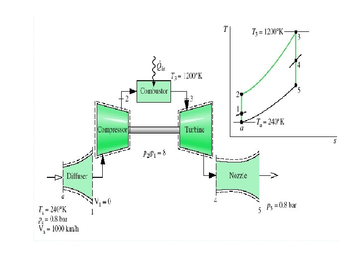

Assumptions: 1. Each component is analyzed as a control volume at steady state. The control volumes are shown on the accompanying sketch by dashed lines. 2. The diffuser, compressor, turbine, and nozzle processes are isentropic. 3. There is no pressure drop for flow through the combustor. 4. The turbine work output equals the work required to drive the compressor. 5. Except at the inlet and exit of the engine, kinetic energy effects can be ignored. Potential energy effects are negligible throughout. 6. The working fluid is air modeled as an ideal gas.

Analysis: To determine the velocity at the exit to the nozzle, the mass and energy rate balances for a control volume enclosing this component reduce at steady state to give where is the mass flow rate. The inlet kinetic energy is dropped by assumption 5. Solving for V 5

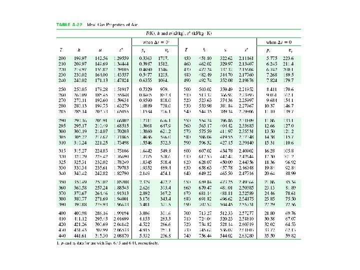
Mass and energy rate balances for a control volume enclosing the diffuser reduce to give With ha from Table A-22 and the given value of Va

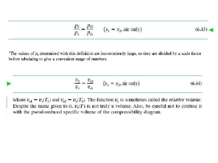
Interpolating in Table A-22 gives pr 1 = 1. 070. The flow through the diffuser is isentropic, so pressure p 1 is With pr data from Table A-22 and the known value of pa Using the given compressor pressure ratio, the pressure at state 2 is p 2 =8(1. 347 bars) = 10. 78 bars The flow through the compressor is also isentropic. Thus

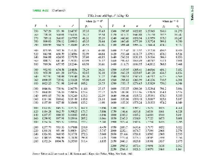
Interpolating in Table A-22, we get h 2 = 505. 5 k. J/kg. At state 3 the temperature is given as T 3= 1200 K. From Table A-22, h 3 =1277. 79 k. J/kg. By assumption 3, p 3 = p 2. The work developed by the turbine is just sufficient to drive the compressor (assumption 4). That is

Solving for h 4 Interpolating in Table A-22 with h 4, gives pr 4 =116. 8. The expansion through the turbine is isentropic, so With p 3 =p 2 and pr data from Table A-22 The expansion through the nozzle is isentropic to p 5=0. 8 bars. Thus

From Table A-22, h 5 =65. 8 Btu/ lb, which is the remaining specific enthalpy value required to determine the velocity at the nozzle exit. Using the values for h 4 and h 5 determined above, the velocity at the nozzle exit is
- Slides: 73