
Introduction to Computer Graphics with Web GL Ed
Introduction to Computer Graphics with Web. GL Ed Angel Professor Emeritus of Computer Science Founding Director, Arts, Research, Technology and Science Laboratory University of New Mexico Angel and Shreiner: Interactive Computer Graphics 7 E © Addison Wesley 2015 1
Classical Viewing Ed Angel Professor Emeritus of Computer Science University of New Mexico Angel and Shreiner: Interactive Computer Graphics 7 E © Addison Wesley 2015 2
Objectives • Introduce the classical views • Compare and contrast image formation by computer with how images have been formed by architects, artists, and engineers • Learn the benefits and drawbacks of each type of view Angel and Shreiner: Interactive Computer Graphics 7 E © Addison Wesley 2015 3
Classical Viewing • Viewing requires three basic elements One or more objects A viewer with a projection surface Projectors that go from the object(s) to the projection surface • Classical views are based on the relationship among these elements The viewer picks up the object and orients it how she would like to see it • Each object is assumed to constructed from flat principal faces Buildings, polyhedra, manufactured objects Angel and Shreiner: Interactive Computer Graphics 7 E © Addison Wesley 2015 4

Planar Geometric Projections • Standard projections project onto a plane • Projectors are lines that either converge at a center of projection are parallel • Such projections preserve lines but not necessarily angles • Nonplanar projections are needed for applications such as map construction Angel and Shreiner: Interactive Computer Graphics 7 E © Addison Wesley 2015 5

Classical Projections Angel and Shreiner: Interactive Computer Graphics 7 E © Addison Wesley 2015 6
Perspective vs Parallel • Computer graphics treats all projections the same and implements them with a single pipeline • Classical viewing developed different techniques for drawing each type of projection • Fundamental distinction is between parallel and perspective viewing even though mathematically parallel viewing is the limit of perspective viewing Angel and Shreiner: Interactive Computer Graphics 7 E © Addison Wesley 2015 7
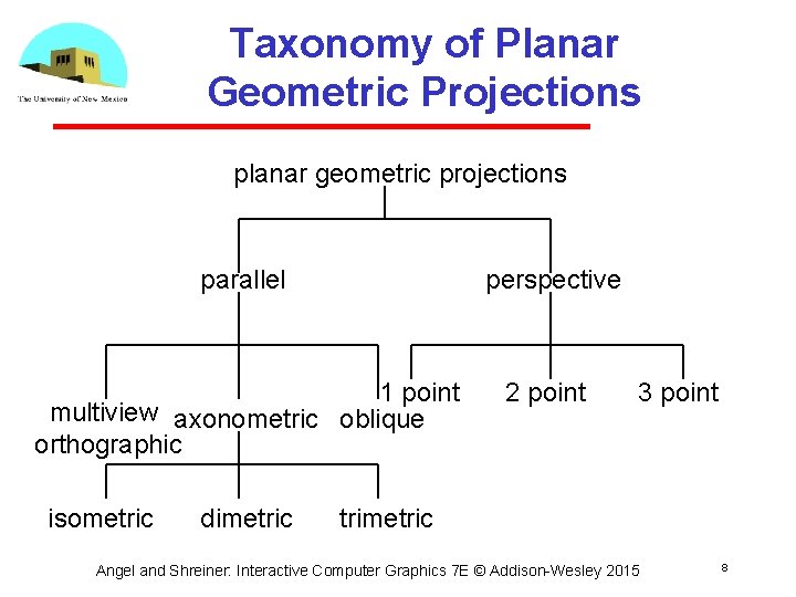
Taxonomy of Planar Geometric Projections planar geometric projections perspective parallel 1 point multiview axonometric oblique orthographic isometric dimetric 2 point 3 point trimetric Angel and Shreiner: Interactive Computer Graphics 7 E © Addison Wesley 2015 8
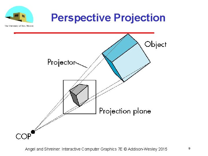
Perspective Projection Angel and Shreiner: Interactive Computer Graphics 7 E © Addison Wesley 2015 9
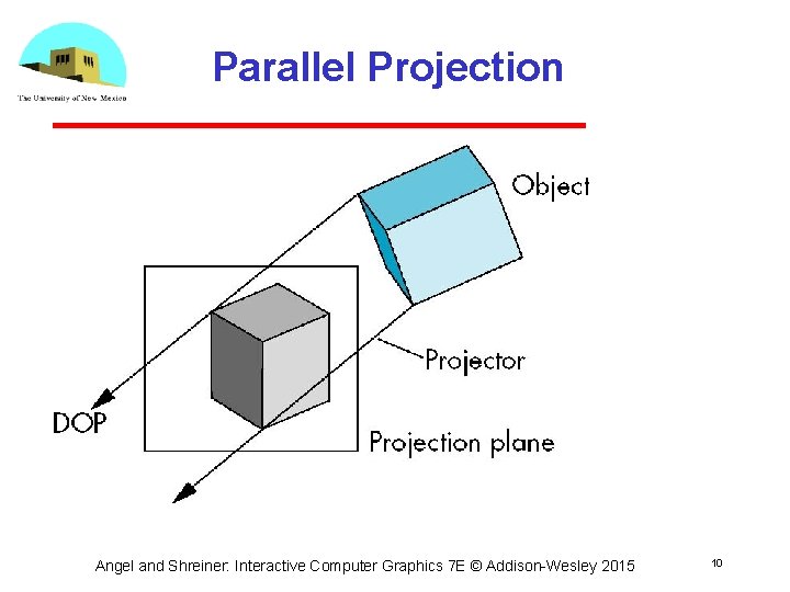
Parallel Projection Angel and Shreiner: Interactive Computer Graphics 7 E © Addison Wesley 2015 10
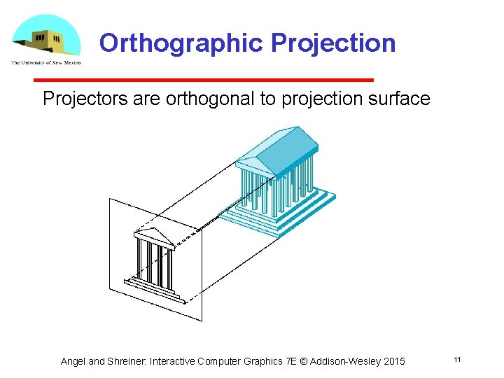
Orthographic Projection Projectors are orthogonal to projection surface Angel and Shreiner: Interactive Computer Graphics 7 E © Addison Wesley 2015 11
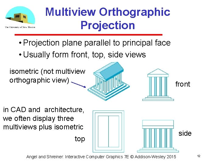
Multiview Orthographic Projection • Projection plane parallel to principal face • Usually form front, top, side views isometric (not multiview orthographic view) front in CAD and architecture, we often display three multiviews plus isometric top Angel and Shreiner: Interactive Computer Graphics 7 E © Addison Wesley 2015 side 12
Advantages and Disadvantages • Preserves both distances and angles Shapes preserved Can be used for measurements • Building plans • Manuals • Cannot see what object really looks like because many surfaces hidden from view Often we add the isometric Angel and Shreiner: Interactive Computer Graphics 7 E © Addison Wesley 2015 13
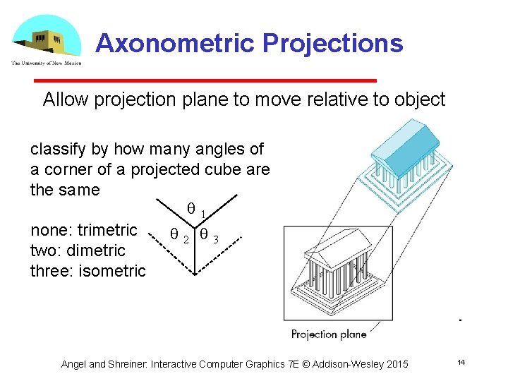
Axonometric Projections Allow projection plane to move relative to object classify by how many angles of a corner of a projected cube are the same q 1 none: trimetric q 2 q 3 two: dimetric three: isometric Angel and Shreiner: Interactive Computer Graphics 7 E © Addison Wesley 2015 14
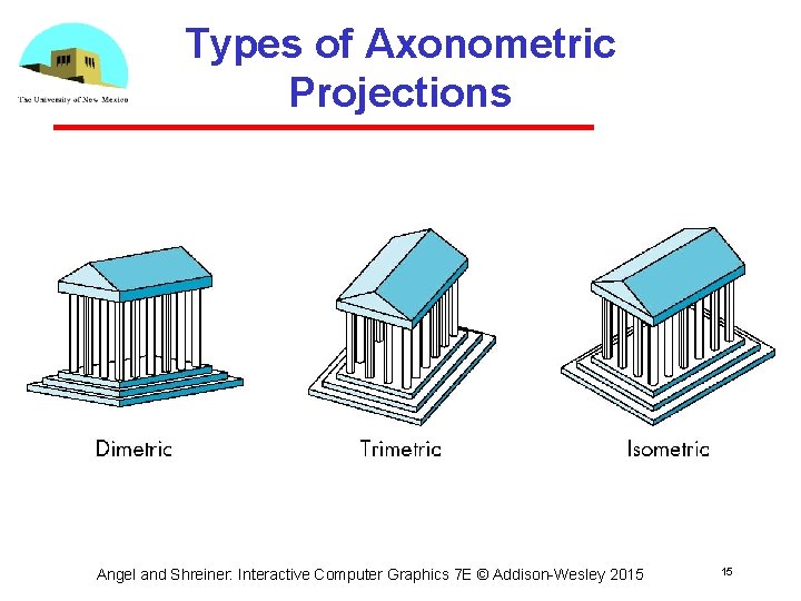
Types of Axonometric Projections Angel and Shreiner: Interactive Computer Graphics 7 E © Addison Wesley 2015 15
Advantages and Disadvantages • Lines are scaled (foreshortened) but can find scaling factors • Lines preserved but angles are not Projection of a circle in a plane not parallel to the projection plane is an ellipse • Can see three principal faces of a box like object • Some optical illusions possible Parallel lines appear to diverge • Does not look real because far objects are scaled the same as near objects • Used in CAD applications Angel and Shreiner: Interactive Computer Graphics 7 E © Addison Wesley 2015 16
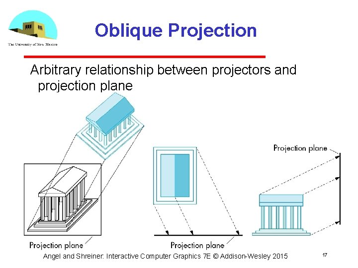
Oblique Projection Arbitrary relationship between projectors and projection plane Angel and Shreiner: Interactive Computer Graphics 7 E © Addison Wesley 2015 17
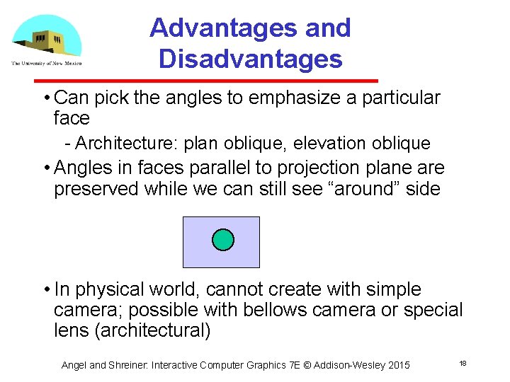
Advantages and Disadvantages • Can pick the angles to emphasize a particular face Architecture: plan oblique, elevation oblique • Angles in faces parallel to projection plane are preserved while we can still see “around” side • In physical world, cannot create with simple camera; possible with bellows camera or special lens (architectural) Angel and Shreiner: Interactive Computer Graphics 7 E © Addison Wesley 2015 18
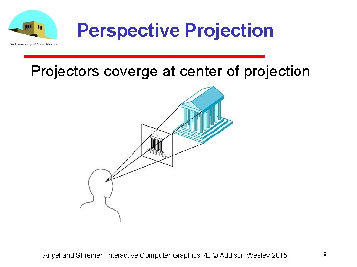
Perspective Projection Projectors coverge at center of projection Angel and Shreiner: Interactive Computer Graphics 7 E © Addison Wesley 2015 19
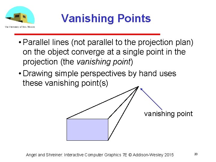
Vanishing Points • Parallel lines (not parallel to the projection plan) on the object converge at a single point in the projection (the vanishing point) • Drawing simple perspectives by hand uses these vanishing point(s) vanishing point Angel and Shreiner: Interactive Computer Graphics 7 E © Addison Wesley 2015 20
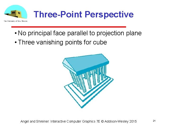
Three-Point Perspective • No principal face parallel to projection plane • Three vanishing points for cube Angel and Shreiner: Interactive Computer Graphics 7 E © Addison Wesley 2015 21
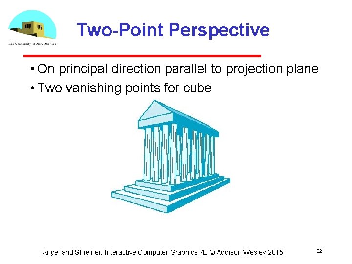
Two-Point Perspective • On principal direction parallel to projection plane • Two vanishing points for cube Angel and Shreiner: Interactive Computer Graphics 7 E © Addison Wesley 2015 22
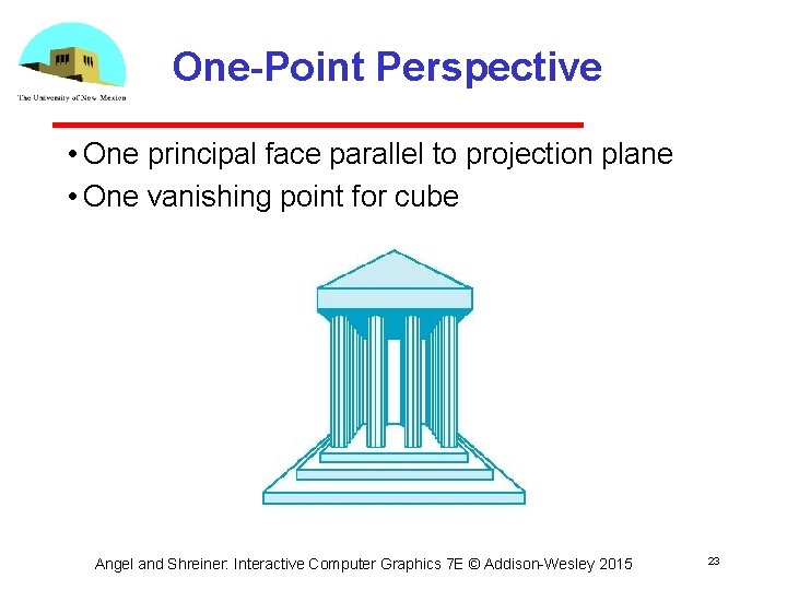
One-Point Perspective • One principal face parallel to projection plane • One vanishing point for cube Angel and Shreiner: Interactive Computer Graphics 7 E © Addison Wesley 2015 23
Advantages and Disadvantages • Objects further from viewer are projected smaller than the same sized objects closer to the viewer (diminution) Looks realistic • Equal distances along a line are not projected into equal distances (nonuniform foreshortening) • Angles preserved only in planes parallel to the projection plane • More difficult to construct by hand than parallel projections (but not more difficult by computer) Angel and Shreiner: Interactive Computer Graphics 7 E © Addison Wesley 2015 24
- Slides: 24