Introduction to ASIC flow and Verilog HDL What

 – used to")


")


 Continuous assignment use the assign keyword. A simple natural")

 An alternative, often higher level of abstraction in behavioral class")


; input Cin; input x,")


")


")


:")


:")


")


- Slides: 68
Introduction to ASIC flow and Verilog HDL
What is Verilog ? IEEE industry standard Hardware Descriptive Language (HDL) – used to describe a digital system Used in both hardware simulation and synthesis HDL : A text programing language used for model a piece of hardware
More Terminology: Register Transfer Level : A type of behavioral modeling, for the purpose of synthesis. Synthesis : Translating HDL to a circuit and then optimizing the represented circuit. RTL Synthesis : Translating the RTL model of hardware into an optimized technology specific gate level implementation.
What is Synthesis?
Synthesis Implementation (Basic)
Basic VLSI Design Flow:
Synthesis vs Simulation
Synthesis Flow
Basics of Combinational Digital Design Using a NAND gate, how many ways can you come up with an Inverter?
Implementing an Inverter using 2: 1 MUX Equation of the Mux : Output = S * A + S (bar) * B If we replace A with zero and B with 1 we get the functionality of an Inverter Output = S * 0 + S (bar) * 1 Output = S (bar) You can verify using truth tables, the following circuit describes an inverter using 2: 1 MUX
And Gate using 2: 1 MUX Equation of the Mux : Output = S * A + S (bar) * B Tie Input B to zero we get Output = S*A (AND gate)
2: 1 MUX using only NAND Gates
Verilog : The module
Behavioral Description (Continuous /Dataflow Assignment) Continuous assignment use the assign keyword. A simple natural way to express the circuit. Specify the logic expression instead of describing the gate level. HDL more useful if used as a higher level of abstraction. The RHS is continuously evaluated as a function of arbitrarily changing inputs The target / output is a net driven by combinational logic
Implementation of a Dataflow Assignment
Behavioral Description (Procedural Assignment) An alternative, often higher level of abstraction in behavioral class Two structured procedural statements : always and initial. Rather than specifying a circuit by Boolean expression, we use if – else (case, while, for statements) Supports richer control structures and provides greater flexibility.
Mux Implementation of Procedural statement with always
Gate Level : Structural Description Provides gate level details of the design. Net represents connections between hardware elements. Nets are declared with the keyword wire This coding style is error prone, it’s used only when we are sure about the exact circuit implementation Verilog supports basic logic gates as primitives : and, or, nor, NAND, XOR, XNOR, NOT, buf
Structural Implementation of MUX
Verilog Registers In digital design registers represents memory elements. Digital registers need a clock to operate and update their state at a particular edge. Registers in Verilog are different from digital design, please don’t confuse In Verilog (reg) simple means a variable that can hold value, which can be changed anytime by assigning a new one
Combining Procedural and Continuous
The case statement: Case and if can be used interchangeably to implement conditional execution within always blocks. Case statements can be more easily read
N - bit signals in verilog 2: 1 MUX with 8 – bit operands.
Multi bit arithmetic the easy way:
Port Connection Implementation
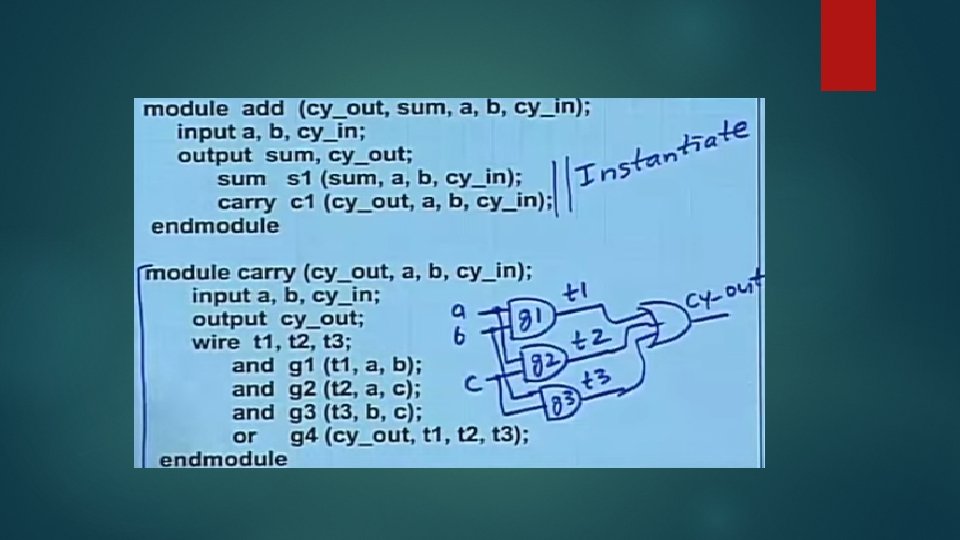
Connecting module instantiation Ports module Full_Adder(Cin, x, y, Cout, s); input Cin; input x, y; output Cout; output s; wire c 1, c 2, s 1; Half_Add HA 1(x, y, c 1, s 1); Half_Add HA 2(s 1, Cin, c 2, s); assign Cout = c 1 | c 2; endmodule
Basic Verilog Construct
Verilog Combinational Logic
Alternative coding style for CL
Combined Verilog code for Flip Flop
Incorrect specification in Verilog: Use always block sensitivity list to wait for clock to change
Sequential vs Combinational in always block
Synchronous vs Asynchronous clear
Implementing Asynchronous/Synchronous Reset
Verilog Implementation for Asynch/Synch Reset
Synchronous vs Asynchronous -III
Synchronous vs Asynchronous Reset
Getting the best of both worlds: Synchronize the asynchronous external reset signal. Use this synchronous signal as input to all asynchronous flip flops. Asynch reset FF takes less logic to implement, consumes less power.
The Asynchronous Metastable Problem
Blocking vs Non-Blocking
Swap function using blocking/non blocking
Assignment style for Sequential design
Use Non-Blocking for Sequential Logic
Use Blocking for Combinational Logic
Structural Representation (Revisited)
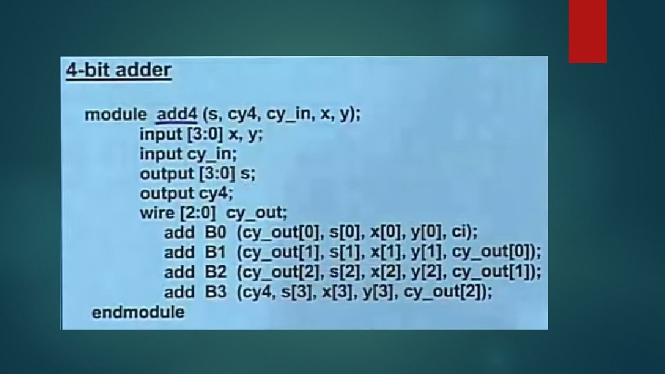
Structural Representation of a 4 -bit Adder
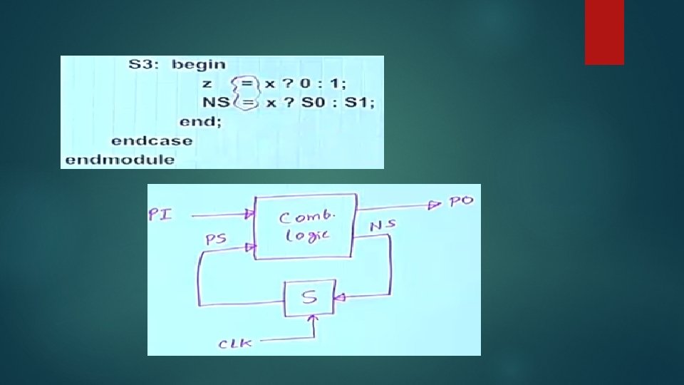
Modeling Finite State Machines
Moore Machine example
Code for Traffic light controller
Traffic light controller code(contd. )
Further thoughts:
Non-latched Traffic light controller code:
Non-latched code (continued):
Moore Machine : Example 2
Code for parity detector:
Parity Detector code (continued):
Reasoning it’s a Moore
Mealy Machine : Example
Sequence Detector : Code
Sequence Detector code : (continued)
Example with Multiple Modules
The Compliment module
The Adder Module
The parity checker module
Top Level Module: Interconnecting the lower level modules