Introduction to AC Circuits Inductor Capacitor CONTENTS CAPACITORS


.")


 microfarad (µF)")
 • According to passive sign convention, current is considered to flow")
 1. Voltage-current relation of the capacitor can be obtained by integrating")


 Calculate the charge stored on a 3 -p. F capacitor with 20")


 Charging network: -Electron drawn form top plate and")
 Transient period – a period of time where")
 Two ways to excited the circuit: i. By")


 / Vo 0. 36788 0. 13534 0.")

, we can find the current i. R(t) as")

 = 15 V. Find Vc, Vx and")


 for t≥")

=45 V, Determine Vc , Vx and io")
")


=10 A, calculate i(t) and ix(t) in")


 from i 1 using voltage division; i 1 2Ω t>0")


- Slides: 73
Introduction to AC Circuits - Inductor & Capacitor
CONTENTS • CAPACITORS • SERIES AND PARALLEL CAPACITANCE • INDUCTORS • SERIES AND PARALLEL INDUCTORS • TRANSIENT RESPONSE CAPACITIVE NETWORK: CHARGING PHASE • TRANSIENT RESPONSE INDUCTIVE NETWORK
INTRODUCTION 1. Two new important passive linear circuit elements: capacitors and inductors. 2. Capacitors and inductors do not dissipate energy but store energy. 3. Therefore capacitors and inductors are called storage elements.
CAPACITORS • A capacitor is a passive elements designed to store energy in its electric field. • Capacitors are the most important common electrical component and extensively used in electronics, communication, computer, and power system. • Example, they are used in the tuning circuits of radio receivers and as dynamics memory elements in computer system.
CAPACITORS A capacitor consists of two conducting plates separated by an insulator (or dielectric). • Practically, the plates may be aluminum foil ; dielectric may be air ceramic, paper and mica.
CAPACITORS • When a voltage source v is connected to the capacitor, the source deposits a positive charge (+q ) on one plate and a negative charge (–q) on the other. • The capacitor is said to store the electric charge. • The amount of charge stored (q), is directly proportional to the applied voltage, so: Where C, the constant of proportionality, known as capacitance of capacitor. q= amount of charge stored, v= applied voltage and C=capacitance of the capacitor
CAPACITORS Capacitance is the ratio of the charge on one plate of a capacitor to the voltage difference between the two plates, measured in farads (F). Capacitance is a measure of capacitor’s ability to stored charge on its plates. (Its storage capacity) The higher capacitance of a capacitor, the greater is the amount of charge stored on the plates for the same applied voltage.
1 farad = 1 coulomb of charge / volt Q = amount of charge stored, V = applied voltage and C = capacitance of the capacitor 1 coulomb of charge = 6. 242 x 1018 electrons Answer: Then, Question : First find the number of charge in coloumbs: If 82. 4 x 10¹⁴ electrons are deposited on the negative plate of 82. 4 x 10¹⁴ electrons C / 6. 242 x a capacitor byx ( 1 an applied voltage of 60 V, find the 18 10 electrons ) capacitance of the capacitor. = 1. 32 m. C
CAPACITANCE • Capacitance, C of a capacitor depends on the physical dimensions of the capacitor. • Three factors determine the value of capacitance: a) The surface area of the plate – the larger the area, the greater the capacitance. b) The spacing between the plates – the smaller the spacing , the greater capacitance. c) The permittivity of the material – the higher the permittivity, the greater the capacitance • Example: for parallel plate capacitor, the capacitance is C= capacitance, given: A= surface area of each plate d= distance between plate ε = permittivity of the dielectric material between plates
CAPACITORS Typical range value for capacitor: picofarad (p. F) microfarad (µF)
CAPACITIVE CURRENT (ic) • According to passive sign convention, current is considered to flow into the positive terminal of the capacitor when the capacitor is being charges, and out of the positive terminal when the capacitor is discharging. • The capacitive current is directly related to the rate of change of the voltage across the capacitor. • Current-voltage relationship of the capacitor: • The factor C reveal that higher capacitance, the greater is the resulting current. The capacitor that satisfy this equation are said to be linear.
CAPACITIVE VOLTAGE (VC) 1. Voltage-current relation of the capacitor can be obtained by integrating both side of previous equation. We get or This equation shows that capacitor voltage depends on the past history of the capacitor current. Means that the voltage across the capacitor at time t 0
CAPACITORS • • The instantaneous power delivered to the capacitor is: The energy stored in the capacitor:
CAPACITORS Take note of the important properties of a capacitor: 1. From the voltage-current relation equation, note that when the voltage across a capacitor is not charging with time (i. e dc voltage), the current through the capacitor is zero. A capacitor is act as an open circuit to dc.
2. The voltage on the capacitor must be continuous. The capacitor resists an abrupt change in the voltage across it. The voltage on a capacitor cannot change abruptly.
CAPACITORS 3. The ideal capacitor does not dissipate energy. It takes power from the circuit when storing energy in its field and returns previously stored energy when delivering power to the circuit. 4. A real, nonideal capacitor has a parallel-model leakage resistance(as high as 100 M Ohm), and can be neglected for most practical applications.
Example: a) Calculate the charge stored on a 3 -p. F capacitor with 20 V across it. b) Find the energy stored in the capacitor.
Example 1. What is the voltage across a 3µF capacitor if the charge on one plate 0. 12 m. C? How much energy stored? 2. The voltage across a 5µF capacitors is v(t)= 10 cos 6000 t V. Calculate the current through it. 3. Determine the voltage across a 2µF capacitor if the current through it is i(t) = 6 e-3000 t m. A. Assume that the initial capacitor voltage is zero. Figure 1 4. Obtain the energy stored in each capacitor in Figure 1 under dc condition. 6 m. A Ω Ω
SERIES AND PARALEL CAPACITORS • Consider the following parallel-connected capacitors circuit: Parallel-connected N capacitors Equivalent circuit for the parallel capacitors • Equation: • Equivalent capacitance of N parallel-connected capacitors=the sum of the individual capacitance. • Capacitors in parallel combine in the same manner as resistors in series.
SERIES AND PARALEL CAPACITORS • Series connected N capacitors: Series-connected N capacitors Equivalent circuit for the series capacitors • Equation: • Equivalent capacitance of series-connected capacitors=the reciprocal of the sum of the reciprocals of the individual capacitances. • Capacitors in series combine in the same manner as resistors in parallel. • For N=2 (two capacitors in series):
SERIES AND PARALEL CAPACITORS Example: Find the equivalent capacitance seen between terminals a and b of the circuit shown.
SERIES AND PARALEL CAPACITORS Increasing level of capacitance can be obtained by replacing capacitors in parallel. Decreasing level of capacitance can be obtained by replacing capacitors in series. For capacitors in series, the charge is the same on each capacitor. Q 1 Q 2 Q 3 QN
SERIES AND PARALEL CAPACITORS The voltage across each capacitor in series can be found by recognizing that CT = total capacitance in series network Cx = individual capacitance in series network Vx = voltage across individual capacitor in series network
SERIES AND PARALEL CAPACITORS For capacitors in parallel , voltage across each capacitor is same and the total charge is the sum of that on each capacitor. Q 1 Q 2 Q 3 QN
SERIES AND PARALEL CAPACITORS Example: Find the voltage across each capacitor.
SERIES AND PARALEL CAPACITORS Solution: Equivalent capacitance:
Exercise Three capacitors C 1=5μF, C 2=10μF and C 3=5μF are connected in parallel across a 150 V source. Determine: a) The total capacitance b) The charge on each capacitor c) Total energy stored in the parallel combination
INDUCTORS • Inductor – passive element designed to store energy in its magnetic field. • Used in power supplies, transformers, radios, TVs, radars, electric motors. • An inductor consists of a coil of conducting wire. • Inductance is the property whereby an inductor exhibits opposition to the change of current flowing through it, measured in henrys (H). • Inductance of an inductor depends on its physical dimension and construction.
INDUCTORS L= inductance, N= number of turns l= length A=cross-sectional area µ =permeability of the core
INDUCTORS • Inductors may be fixed or variable. The core maybe made of iron, steel, plastic or air. • The circuit symbols for inductor as below following the passive sign convention
INDUCTORS • Voltage – current relation: • Current – voltage relation: • Power delivered to the inductor: • Energy stored:
INDUCTORS Important properties: 1. Voltage across an inductor is zero when the current is constant. An inductor acts like a short circuit to dc. 2. An important property of the inductor is its opposition to the change in current flowing through it. The current through an inductor cannot change instantaneously.
INDUCTORS 1. Like the ideal capacitor, the ideal inductor does not dissipate energy. 2. A practical, nonideal inductor has a significant resistive component, due to the fact that the inductor is made of a conducting material such as copper, which has some resistance. This resistance is called winding resistance Rw. It is also has a winding capacitance Cw due to the capacitive coupling between the conducting coils. Since both values are very small, they can be ignored in most cases.
SERIES AND PARALEL INDUCTORS • Consider a series connection of N inductors: A series connection of N inductors Equivalent circuit for the series inductors Equation: • The equivalent inductance in series-connected inductors is the sum of the individual inductances. • Inductors in series are combined in exactly the same way as resistor in series.
SERIES AND PARALEL INDUCTORS • Consider a parallel connection of N inductors: A parallel connection of N inductors Equation: Equivalent circuit for the parallel inductors
SERIES AND PARALEL INDUCTORS • The equivalent inductance of parallel inductors is the reciprocal of the sum of the reciprocals of the individual inductances • The inductors in parallel are combined in the same way as resistors in parallel. • For two inductors in parallel (N=2)
SERIES AND PARALEL INDUCTORS Example: Find the equivalent inductance of the circuit shown.
SERIES AND PARALEL INDUCTORS Example: 2 H
SERIES AND PARALEL INDUCTORS Solution:
SUMMARY
FURTHER READING… 1. Fundamentals of Electric Circuits, Sixth Edition, Mc. Grawhill Alexander, C. K. and Sadiku, M. N. O. 2. Electric Circuit, 8 th Edition, Pearson, Nillson and Riedel. 3. Circuits, Brooks/ Cole, A. Bruce Carlson.
TRANSIENT IN CAPACITIVE NETWORKS (Charging Phase) Charging network: -Electron drawn form top plate and deposit to bottom plate by the battery. - Transfer electron very rapid at first and slowing down as the potential across the capacitor approaches to the applied battery. -Fully charge : Vc=E - Q=CVc=CE
TRANSIENT IN CAPACITIVE NETWORKS (Charging Phase) Transient period – a period of time where the voltage or current changes from one steady state level to another.
TRANSIENT IN CAPACITIVE NETWORKS (Charging Phase) Two ways to excited the circuit: i. By initial condition of the storage elements in the circuit socalled source-free circuits. We assume that energy is initially stored in the capacitive and inductive element. Ø Energy causes current flow in the circuit and is gradually dissipated in the resistors. ii. Exciting the circuit by independent sources. (Consider dc sources)
Source-Free RC Circuit A source-free RC circuit occurs when its dc source is suddenly disconnected. Energy stored in capacitor is released to the resistor. To determine the circuit response, Assume the voltage v(t) across the capacitor. Since the capacitor is initially charged, we can assume that at time t=0, the initial voltage is v(0) = Vo Corresponding value of energy stored as ω(0) = ½(CVo 2 ) First-order differential equation: Applying KCL to the top node of the circuit yields i. C + i R = 0 By definition ;
Source-Free RC Circuit Rearrange the terms Intergrating both side Integration constant Taking power of e produce From the initial condition, v(0)= A=Vo Shows the voltage response of RC circuit is exponential decay of the initial voltage.
Source-Free RC Circuit Natural Response Natural response of a circuit refer to the behavior(in term of voltage and currents) of the circuit itself, with no external sources of excitation. At t=0, we have correct initial condition v(0)= Vo At t increases, the voltage decreases toward zero (expressed in term of time constant, denoted by ). The voltage response of the RC circuit.
Source-Free RC Circuit Time Constant The time constant of a circuit is the time required for response to decay to a factor of 1/e or 36. 8% of the initial value. This implies that at t= In term of time constant, the equation ca be written as τ is the time needed for the Transient Response to decay by a factor of 1/e
Source-Free RC Circuit Time constant… t v(t) / Vo 0. 36788 0. 13534 0. 04979 0. 01832 0. 00674 From this table, the voltage v(t) is less than 1% of Vo after 5 § Assume that the capacitor fully discharged or charged after 5 time constant. §In other word, it takes 5 for a circuit to reach its final state or steady state when no changes take place with time. § Every time interval of time constant, the voltage is reduced by 36. 8% of its previous value. Regardless of the value of t.
Source-Free RC Circuit Time Constant… The smaller time constant, the more rapidly the voltage decreases, that is the faster response. It reach steady state quickly due to quick dissipation of energy stored. Large time constant, slow response because it takes longer to reach the steady state. Plot of v(t) / Vo for various of the time constant
Source-Free RC Circuit From equation v(t), we can find the current i. R(t) as Power dissipated in the resistor is Energy absorbed by a resistor up to time t :
Source-Free RC Circuit When a circuit contain with single capacitor and several resistor and dependent sources, the Thevenin equivalent can be found at terminal of the capacitor to the form a simple RC circuit. Thevenin’s theorem can be used when several capacitor combined to form a single equivalent capacitor. Take out capacitor C and find R=RTh at its terminals. (Where R is equivalent resistance at the terminals of the capacitor. )
Example 1 In Figure 1, let Vc(0) = 15 V. Find Vc, Vx and ix for t>0. Solution: First, find the equivalent resistance of Rth. Figure 1 Time constant : Equivalent circuit : Thus,
Example 1… Can use voltage division to get Vx Finally;
Example 2 The switch in the circuit has been closed for a long time, and it is open at t=0. Find v(t) for t ≥ 0. Calculate the initial energy stored in the capacitor. Solution: For t<0; capacitor open circuit to dc. - Use voltage division Since capacitor cannot change instantateneously , voltage across capacitor:
Example 2… For t>0; switch is open; RC circuit is source free. -Independent source is needed to provide Vo or initial energy in the capacitor. - Find Req: Time constant : Thus, Initial energy,
exercise If the switch in circuit is open at t=0, find v(t) for t≥ 0 and wc(0). Answer: 8 e-2 t V , 5. 333 J
For t <0, the switch is closed, the capacitor is an open circuit to dc. Independent source is needed to provide V 0 or initial energy in the capacitor. First, find the initial voltage across capacitor and initial energy For t >0, the switch is opened, source free RC circuit Find time constant and v(t)
exercise Refer to the circuit, let Vc(0)=45 V, Determine Vc , Vx and io for t≥ 0. Answer: 45 e-0. 25 t V, 15 e-0. 25 t V, -3. 75 e-0. 25 t A
Source-Free RL Circuit Objective – to determine the circuit response Assume the current i(t) through the inductor because the inductor current cannot change instantaneously. At t = 0, assume inductor has initial current Io : i(0) = Io The corresponding energy stored in the inductor is ω(0) = ½(LIo 2 ) i Applying KVL around the loop VL + V R = 0 Source-free RL circuit + VR -
Source-Free RL Circuit Know that and Substitute into the equation. VL + VR = 0 Thus, Rearrange and integrating the differential equation gives
Source-Free RL Circuit Taking power of e, This show the natural response of RL circuit. - An exponential decay of the initial current. Time constant : Unit : Second Rewrite the current i(t) equation: Voltage across the resistor Power dissipated in the resistor
Source-Free RL Circuit Energy absorbed by the resistor Initial energy stored in the inductor. Obtain the response as the inductor current : Once determine the inductor current i. L , then we can obtain other variable like VL, VR and i. R. R is thevenin resistor at terminals of the inductor.
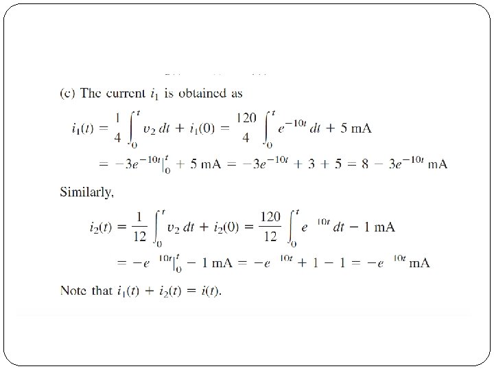
Source-Free RL Circuit Example 1 Assuming that i(0)=10 A, calculate i(t) and ix(t) in the circuit. 4Ω i 0. 5 H Solution: obtain the equivalent resistor at terminals of the inductor then use the equation: ix 2Ω + _ 3 i Notes: always start with obtain the inductor current i. L.
Source-Free RL Circuit 4Ω Dependent source ix i 2Ω 0. 5 H io + _ 3 i 4Ω i 1 2Ω i 2 + _ Substitute equation loop 2 into equation loop 1: 3 i §To find RTh : §Take out the inductor. §Using thevenin’s theorem, if the circuit contain with dependent source, add the external source of 1 V at the terminals of the inductor. §Applying the KVL to the two loops. §At loop 1: §At loop 2: Because of different direction
Hence, Time constant : Thus, the current flow through the inductor is
Source-Free RL Circuit Example 2 The switch in the circuit has been closed for a long time. At t=0, the switch is opened. Calculate i(t) for t>0. t=0 2Ω 4Ω i(t) 40 V 12Ω 16Ω 2 H Solution : When t<0, the switch is closed and inductor will become short-circuited. 16Ω resistor can be ignore because of this short-circuited. Equivalent circuit : i 1 40 V 2Ω t>0 4Ω 12Ω
Example 2… Obtain i(t) from i 1 using voltage division; i 1 2Ω t>0 4Ω i(t) 40 V Since the current through an inductor cannot change instanteneously, When t>0, the switch is open; voltage source is disconnected. Now we have source-free RL circuit. Find the equivalent resistor: 12Ω
Example 2… Time constant Thus,
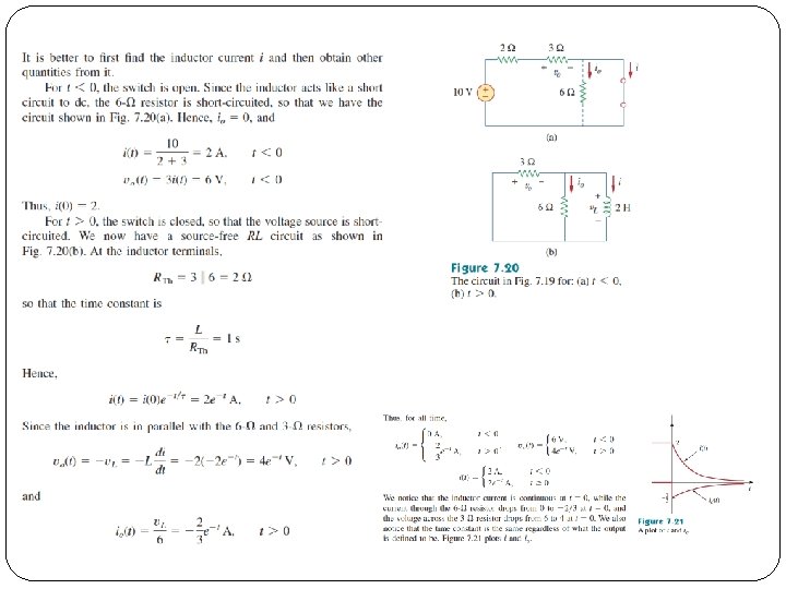
Example Determine io, vo and i for all t in the circuit. Assume that the switch was open for a long time. Plot i and io on the same time axis. 2Ω 3Ω + 10 V Vo - io t=0 6Ω i 2 H