Introduction Sequential Circuits The output of circuit depends


 • What is Flip flop? Answer: • In digital circuits,")


 A BX 00 01 11 0 1 10 1 1 1 B(t+1)")


- Slides: 17
Introduction: Sequential Circuits • The output of circuit depends on the previous output and the present inputs. • The inputs must follow a specific sequence to produce a required output. • In order to follow a sequence of inputs the circuits must contain some form of memory to retain knowledge of those inputs, which have already occurred. • This memory are obtained by feedback connections, which are made so that history of the previous inputs is maintained. • Most sequential systems are based on a small number of simple sequential circuit elements known as Bistables or Flip Flops
Flip Flop (Sequential Circuits) • What is Flip flop? Answer: • In digital circuits, the flip-flop, is a kind of bistable multivibrator. . • It is a Sequential Circuits / an electronic circuit which has two stable states and thereby is capable of serving as one bit of memory , bit 1 or bit 0.
General Flip flop symbol
Circuit j k-flip flop circuit Excitation Table
Q 1: Design circuit J K Flip flop for schema counts down from 12 to 0 by way of even numbers only Answer: 12/1100 0/0000 10/1010 2/0010 8/1000 4/0100 6/0110
Present state Next state A B C D JA KA JB KB JC KC JD KD 0 0 1 1 0 0 1 X 0 X 0 0 0 1 X X X 0 0 1 0 0 0 X 0 X X 1 0 X 0 0 1 1 X X X 0 1 0 0 X X 1 1 X 0 1 0 1 X X X 0 1 1 0 0 0 X X 0 X 1 0 X 0 1 1 1 X X X 1 0 0 1 1 0 X 1 1 X 0 X 1 0 0 1 X X X 1 0 1 0 0 0 X X 1 0 1 1 X X X 1 1 0 0 1 0 X 1 1 X 0 X 1 1 0 1 X X X 1 1 1 0 X X X 1 1 X X X
CD AB 00 01 11 10 00 1 X X 0 00 X X 01 0 X X 0 01 X X X X 11 0 X X X 10 1 X X 0 _ _ JA=B. C _ _ KA=B. C CD AB 00 01 11 10 00 0 X X X 01 1 X X X CD AB 00 01 11 10 11 1 X X X 00 1 X 00 X X 10 1 X X X 01 1 X X 0 11 X X 11 1 X X X 10 1 X X 0 10 X X _ JB=C _ KB=C KC=1 JD=KD=0 JC=A+B
CLK JA QA KA _ QA JB QB KB _ QB JC QC KC _ QC 1 0 JD QD KD _ QD
Q 2: Design a J K Flip flop Of the following schema
Answer:
How to analyze the circuit jk flip flop: Analyze the circuit we need to know characteristic equation Q(t+1) = JQ’ + K’Q
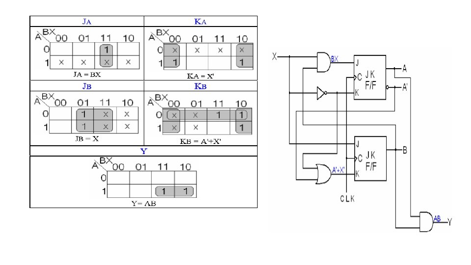
Example : Analysis for circuit J K Flip flop and given the state table , state diagram
Solution: A(t+1) A BX 00 01 11 0 1 10 1 1 1 B(t+1) A BX 0 1 00 1 1 01 11 10 1 1
State Table : State Diagram :