INTRODUCTION Definition Heat exchangers are devices that transfer


 Lifting Lug Air Seal Header")


- Slides: 23
INTRODUCTION Definition: Heat exchangers are devices that transfer or exchange heat from one media to another. It is used either for cooling or for heating purpose. The mediums flowing inside the heat exchanger may be gas or liquid depending upon the service requirements of the process. The transfer of thermal energy (heat) can be accomplished in three ways: Radiation v. Convection v. Conduction
TYPES OF HEAT EXCHANGER n n Shell-and-tube heat exchangers Air-cooled heat exchangers Double-pipe heat exchangers Plate-and-frame heat exchangers
TYPES OF HEAT EXCHANGER
TYPES OF HEAT EXCHANGER
Air-Cooled Heat Exchangers Hood or Plenum Fan Ring Fan Return Headers Inlet Nozzles Inlet Headers Outlet Nozzles Tube Bundle Drive Assembly Supports Horizontal Tube, Induced-Draft Air-Cooled Heat Exchanger
Double-Pipe Heat Exchanger Shell Cover Gasket Vent External Fin Pipe Shell Cover Return Bend (welded) Drain Twin Flange Sliding Support Fixed Support Shell End Piece
SHELL AND TUBE HEAT EXCHANGER v These types of heat exchangers are most commonly industries. and widely used in process v Design criteria: 1. TEMA Standards Tubular Exchanger Manufacturer's Association 2. API 660 (American Petroleum Institute) Standards Shell and Tube Heat Exchangers for General Refinery Services
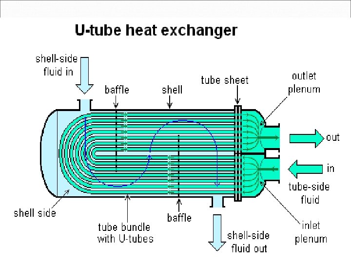
SHELL AND TUBE HEAT EXCHANGER v Basic components of SHELL and TUBE heat exchanger are: Ø Tubes: Provide heat transfer surface Ø Shell or Body: Enclose the area in which fluids flow Ø Nozzles: Inlet and outlet for fluid flow Ø Tube Sheet: Hold the tube in place
SHELL AND TUBE HEAT EXCHANGER Ø Baffles: Support the tubes in proper position and guide the shell side flow to increase heat transfer Ø Channel Cover: Allows tube inspection Ø Pass Divider: Separate the tube side Flow
TYPES SHELL AND TUBE HEAT EXCHANGER v Fixed Tube sheet Ø Ø Ø Tube sheet is welded to the shell. Tube bundle is permanently installed. Used when the temperature range is limited and shell side fouling is limited. v U-Tube or U-Bend: Ø Ø Ø Has only one tube sheet Tube bundle can be removed Used where temperature difference between shell and tube side fluids are high.
TYPES SHELL AND TUBE HEAT EXCHANGER v Floating Head Ø Ø Tube bundle can be pulled out. Tube sheet on one side is bolted between channel and shell. Tube sheet on the other side floats inside the shell and free to move horizontally. Test ring is required for hydro test.
TYPES SHELL AND TUBE HEAT EXCHANGER
FIN FAN COOLER Ø Tubes are Round or Rectangular. Ø Fins generally on the outside of the tubes. Ø Ø For some applications fins may be inside of the tube. Fins are attached to the tubes by a tight mechanical fit, tension winding, adhesive bonding, soldering , brazing and welding etc.
Typical Air-Cooled Heat Exchanger Air Seal Tube Keeper (top) Lifting Lug Air Seal Header Tube Nozzle Header Fins Tube spacer Side Frame Tube Support Air Seal
PLATE HEAT EXCHANGER Ø Ø Consist of a number of corrugated metal plates in mutual contact. Each plate having four ports( Inlet and Outlet).
Aout Bin Nozzle Header Separating Sheet Cin Corrugated Sheet Effective Width Heat Transfer Section Effective A Length Side Bar Distributor Distribution Section Cout Bout Ain Plate-and-Frame Heat Exchanger B
PROBLEMS IN HEAT EXCHANGER v Fouling: Ø Ø Fouling is the build-up of different kinds of deposits on the parts of an exchanger. Fouling effectively increases tube wall thickness due to fouling particles. Pressure drop across exchanger increases. Due to fouling, time of heat transfer increases.
PROBLEMS IN HEAT EXCHANGER v Tube leakage: Removal of metal due to fluid flowing in or across the tube. Ø Can eat away and weaken tube metal which may lead to tube leak v Scale Formation: Ø Build up of solid impurities on the inside of a tube wall. Ø v Tube Leak: Ø It affects heat transfer process.
CLEANING OF HEAT EXCHANGER v The method of cleaning is selected depending upon type of deposit and facilities in the plant. 1. High pressure water jet wash: Ø Ø Ø Hydro jet machine is used. Water jet pressure around 5000 to 10000 PSI. During hydro jet cleaning all required PPE shall be used as the water jet can easily puncture and tear the skin.
CLEANING OF HEAT EXCHANGER 2. Chemical cleaning: Ø Ø Ø Involves circulation of hot wash oil or light distillate through tubes or shell. Cleaning compounds should be compatible with the metallurgy of the exchanger. Sometimes commercial cleaning solutions are used. 3. Mechanical Cleaning: Ø Ø Involves tube cleaning using a wire brush or scrappers. Care should be taken to avoid damaging the tubes
HEAT EXCHANGER MAINTENANCE ACTIVITIES: 1. SCAFFOLDING 2. BLINDING 3. INSULATION REMOVAL 4. DRAINING 5. HEAD COVER REMOVAL 6. PRE-INSPECTION 7. BUNDLE PULLINGOUT/HYDROJET CLEANING 8. TUBE BLOWING 9. SHELL SIDE/TUBE SIDE HYDROTEST/PNEUMATIC TEST 10. IRIS TEST 11. PLUG INSERT/WELD 12. RE-HYDROTEST 13. HEAD COVER BOXUP 14. BLIND REMOVAL
THANKS