
INTRODUCTION DCDC converter chopper is used to convert




- Slides: 17
INTRODUCTION DC-DC converter (chopper) is used to convert constant DC voltage into variable DC voltage. In DC-DC conversion circuits, thyristors are used as switching elements. Here thyristors must be turned off using forced commutation as they lack facility of natural commutation that is available in AC circuits. Buck chopper produces output that is less than or equal to input voltage. Boost chopper provides an output voltage that is greater than or equal to input voltage. Typical application of DC choppers is DC motor speed control. 1
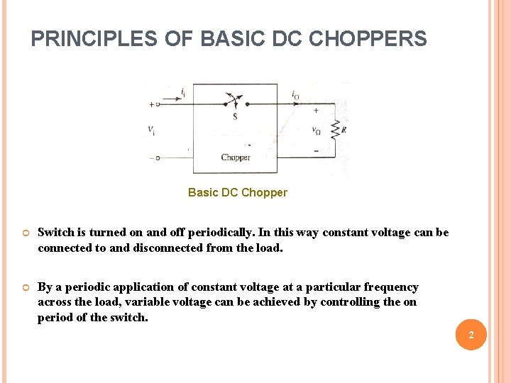
PRINCIPLES OF BASIC DC CHOPPERS Basic DC Chopper Switch is turned on and off periodically. In this way constant voltage can be connected to and disconnected from the load. By a periodic application of constant voltage at a particular frequency across the load, variable voltage can be achieved by controlling the on period of the switch. 2
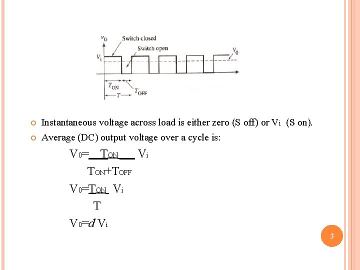
Instantaneous voltage across load is either zero (S off) or Vi (S on). Average (DC) output voltage over a cycle is: V 0= TON Vi TON+TOFF V 0=TON Vi T V 0=d Vi 3
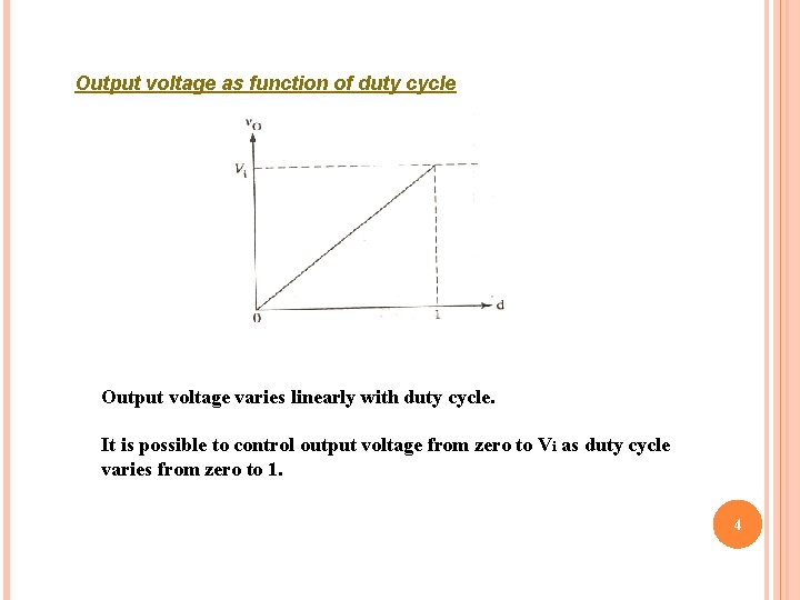
Output voltage as function of duty cycle Output voltage varies linearly with duty cycle. It is possible to control output voltage from zero to Vi as duty cycle varies from zero to 1. 4
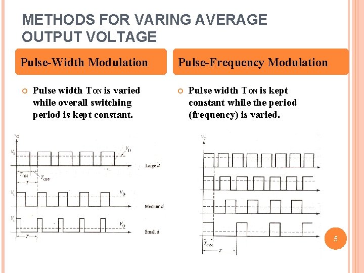
METHODS FOR VARING AVERAGE OUTPUT VOLTAGE Pulse-Width Modulation Pulse width TON is varied while overall switching period is kept constant. Pulse-Frequency Modulation Pulse width TON is kept constant while the period (frequency) is varied. 5
STEP-DOWN (BUCK) CHOPPER 6
Basic Step-Down Chopper circuit Equivalent circuit for on state Equivalent Circuit for off state 7
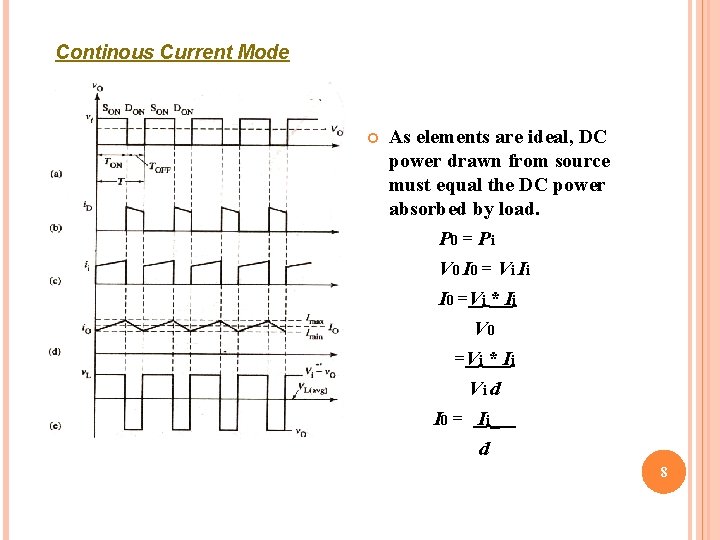
Continous Current Mode As elements are ideal, DC power drawn from source must equal the DC power absorbed by load. P 0 = Pi V 0 I 0 = V i Ii I 0 =Vi * Ii Vi d I 0 = Ii _ d 8
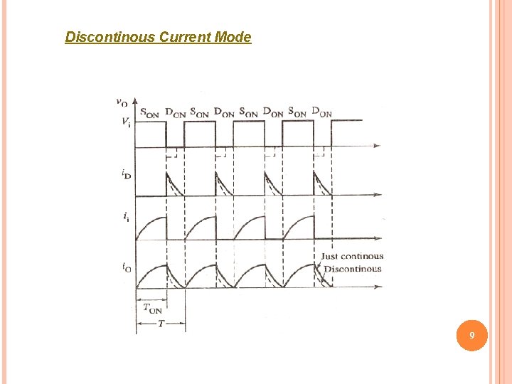
Discontinous Current Mode 9
STEP-UP (BOOST) CHOPPER 10
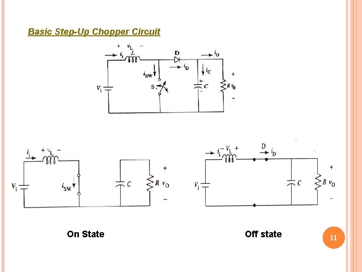
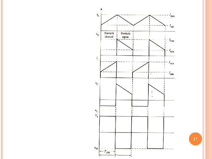
Basic Step-Up Chopper Circuit On State Off state 11
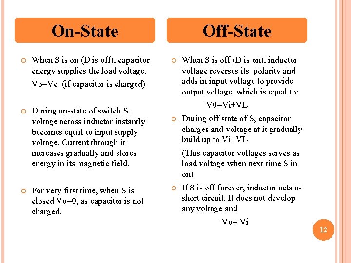
On-State When S is on (D is off), capacitor energy supplies the load voltage. Off-State Vo=Vc (if capacitor is charged) During on-state of switch S, voltage across inductor instantly becomes equal to input supply voltage. Current through it increases gradually and stores energy in its magnetic field. For very first time, when S is closed Vo=0, as capacitor is not charged. When S is off (D is on), inductor voltage reverses its polarity and adds in input voltage to provide output voltage which is equal to: V 0=Vi+VL During off state of S, capacitor charges and voltage at it gradually build up to Vi+VL (This capacitor voltages serves as load voltage when next time S in on) If S is off forever, inductor acts as short circuit. It does not develop any voltage and Vo= Vi 12
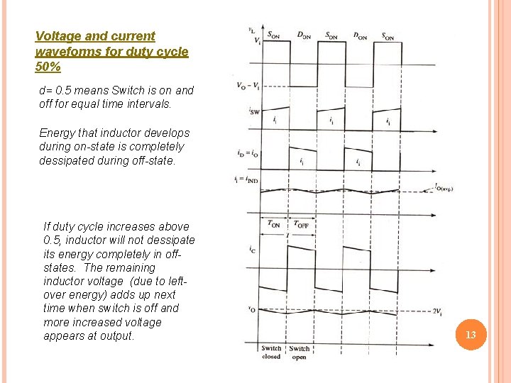
Voltage and current waveforms for duty cycle 50% d= 0. 5 means Switch is on and off for equal time intervals. Energy that inductor develops during on-state is completely dessipated during off-state. If duty cycle increases above 0. 5, inductor will not dessipate its energy completely in offstates. The remaining inductor voltage (due to leftover energy) adds up next time when switch is off and more increased voltage appears at output. 13
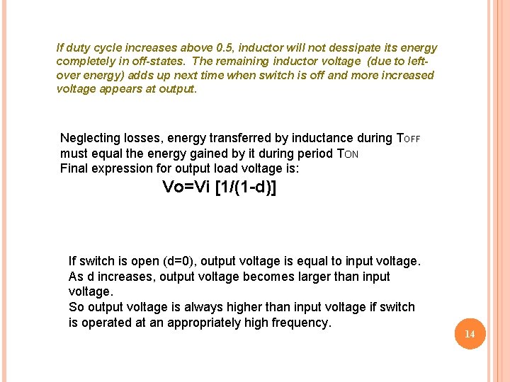
If duty cycle increases above 0. 5, inductor will not dessipate its energy completely in off-states. The remaining inductor voltage (due to leftover energy) adds up next time when switch is off and more increased voltage appears at output. Neglecting losses, energy transferred by inductance during TOFF must equal the energy gained by it during period TON Final expression for output load voltage is: Vo=Vi [1/(1 -d)] If switch is open (d=0), output voltage is equal to input voltage. As d increases, output voltage becomes larger than input voltage. So output voltage is always higher than input voltage if switch is operated at an appropriately high frequency. 14
BUCK-BOOST CHOPPER 15
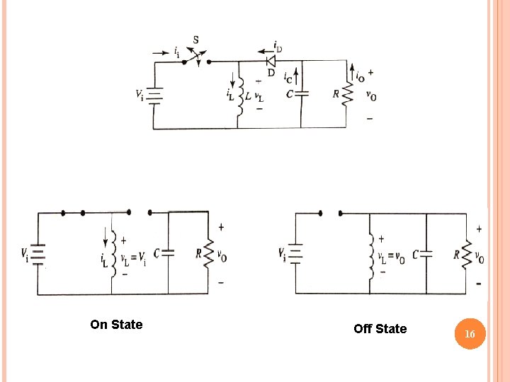
On State Off State 16
17