Introduces Solar Substrate Separator S 3 3 S

Introduces: Solar Substrate Separator, S 3

3 S - “S Cubed” Solar Substrate Separation Equipment for separation of post wire saw substrate for delivery to batch processing or inline solar substrate processing systems

Solar Substrate Separation Challenges: Manual Separation: § Labor intensive § Ergonomic and repetitive motion concerns § High wafer breakage rate Other Automated Separation Methods: § Large foot print § Expensive consumables § Intolerant of varying wafer thicknesses and geometries

Solar Substrate Separation Process: • Operator loads stacks of wet wafers onto a horizontal stack • As more material is added, the stack drops down into the equipment • When the loading is completed, the tool lid is closed, and automated separation begins

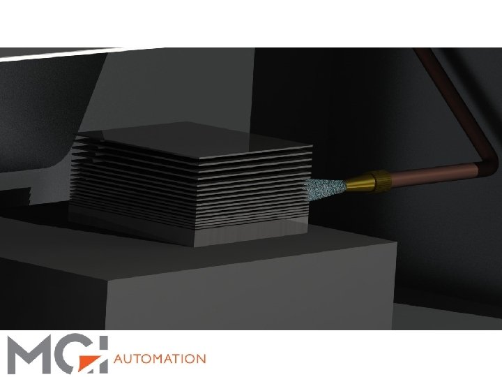
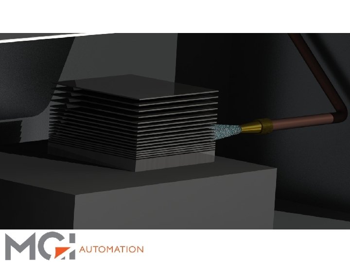
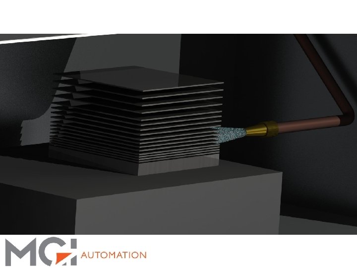
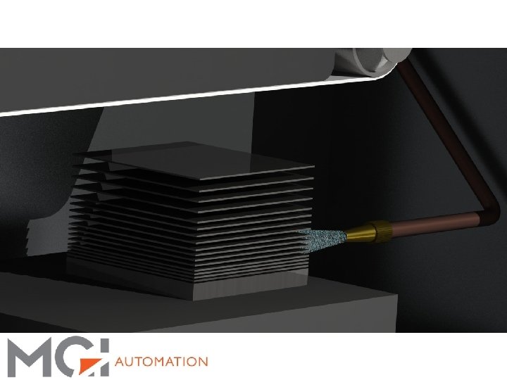
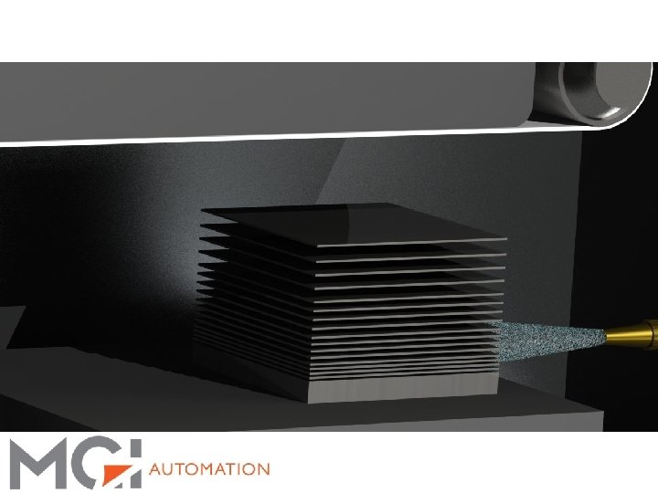
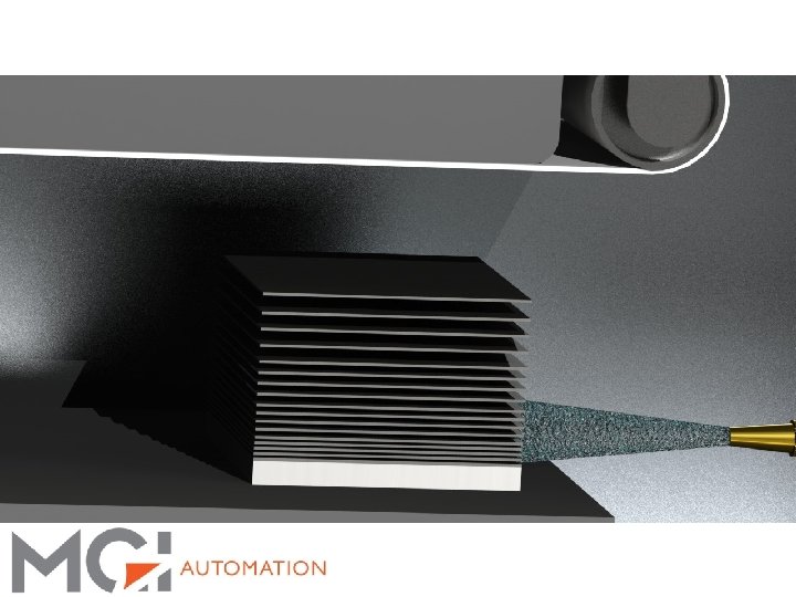
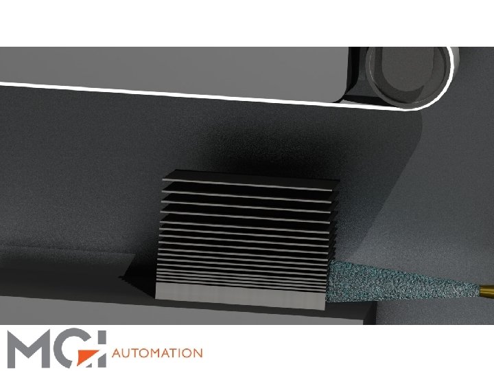
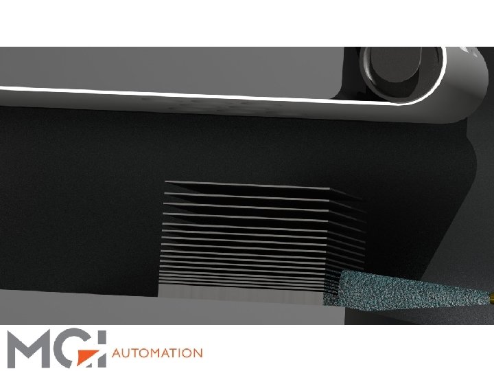
Solar Substrate Separation Process: • The System gently separates the stack of wafers using a water jet enabling the top wafer to be removed from the stack. • Wafer is then delivered to conveyor delivery system for loading into cassettes or in-line systems • Wafer separation is a gentle process that has a low breakage rate

3 S Features: Feature Specification Peak single head separation throughput 1200 Wafers Per Hour Wafer Sizes 125 X 125, 156 X 156, 210 X 210 Pseudo and square 160 Micron and thicker – Tolerant of varying wafer thicknesses Facilities Requirements 100~230 VAC 50/60 Hz, Less than 15 Amps 10 L/hour water Compressed Air ¼” supply @ 80 PSI Wafer Handling Wafers can be kept wet or dry Wafer Breakage Rate <. 5% Single head separation footprint 21” Wide X 32” Long X 48” Tall excluding controls cabinet and substrate handling conveyor system Consumables Inexpensive urethane wear surfaces that are easily replaced Equipment Interface Supports in-line and batch processes

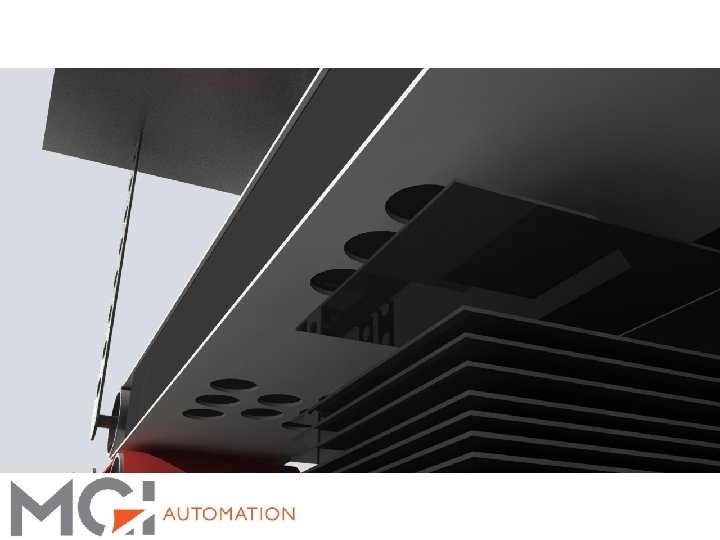
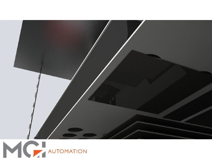
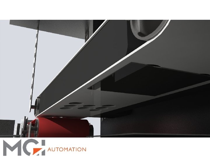
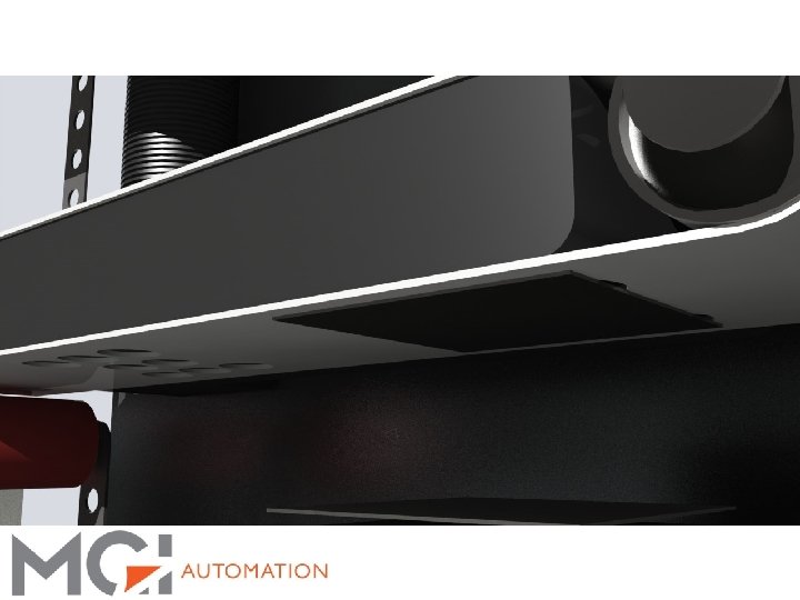
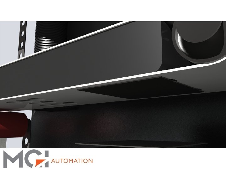
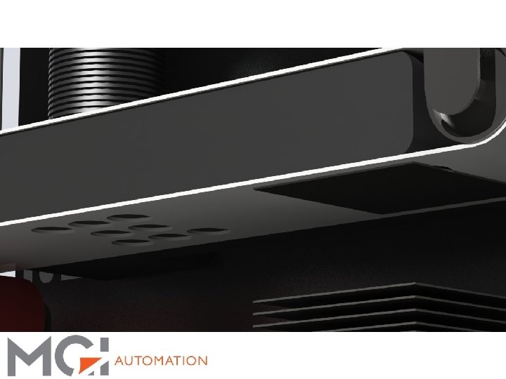
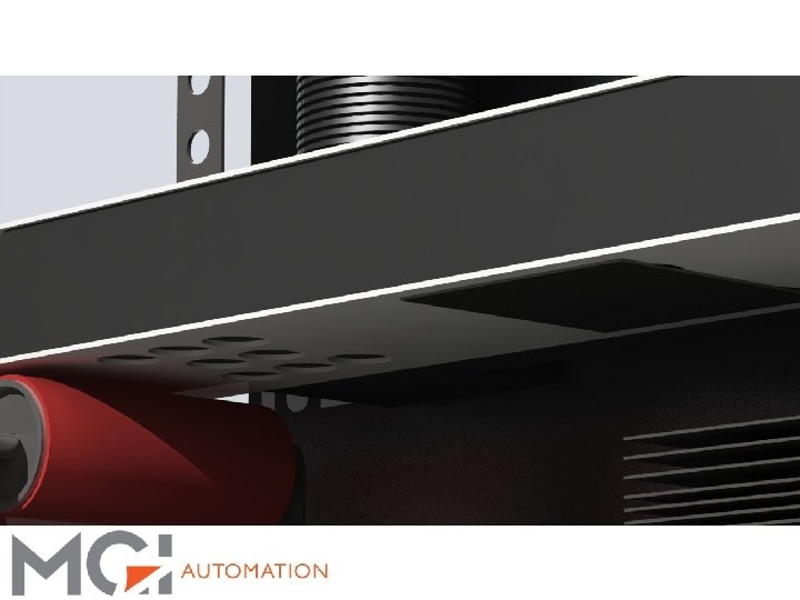
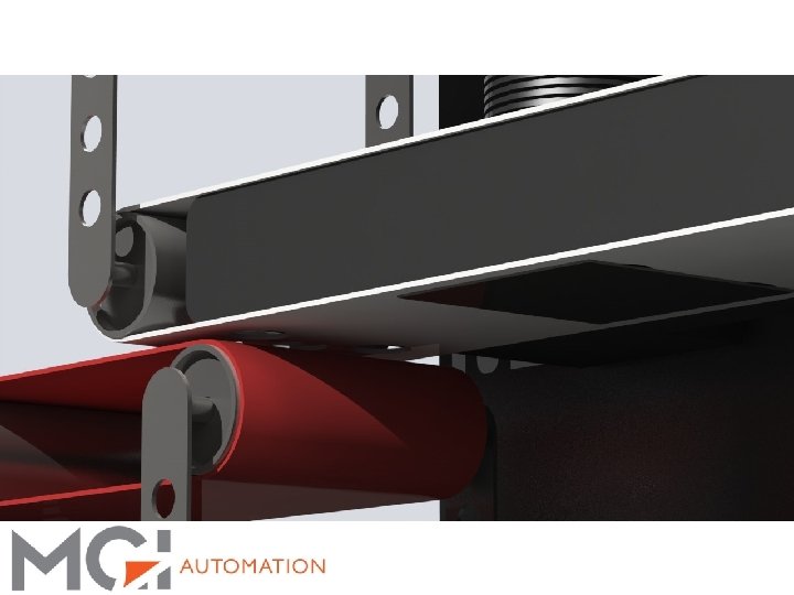
3 S Visualization: Automatic Cassette Loading: § Automated loading of multiple cassettes § Linear option § Rotary option (shown in slides)
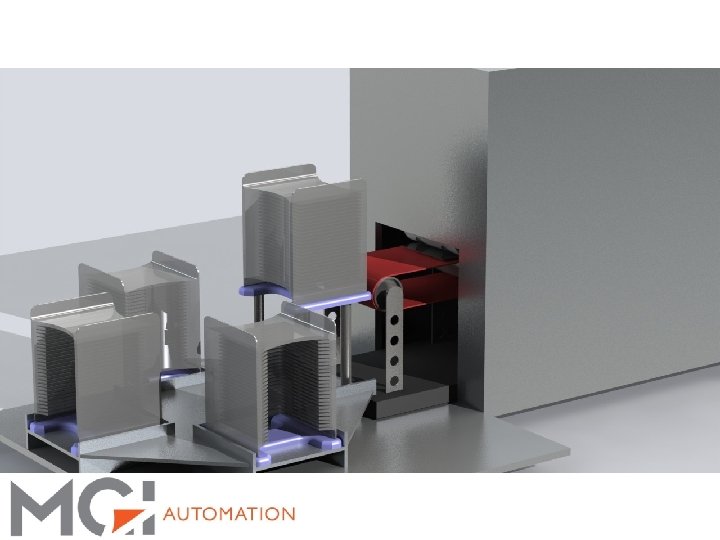
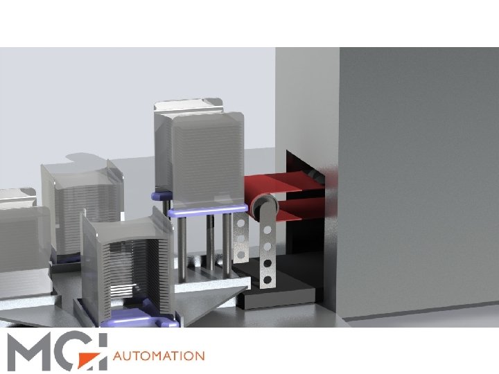
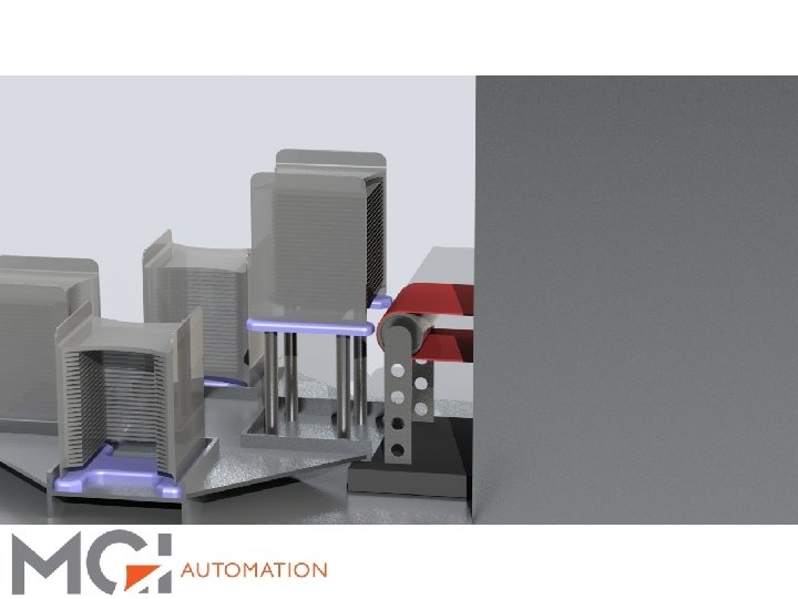
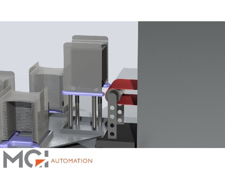

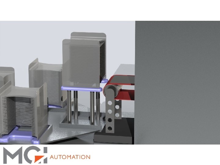
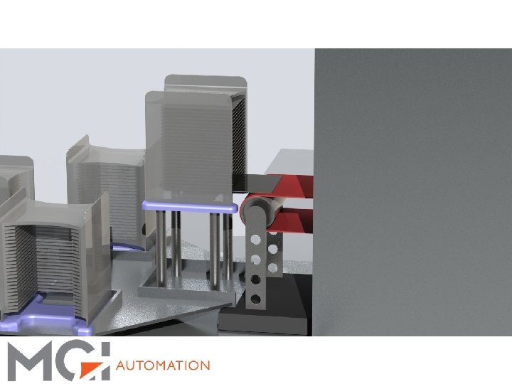
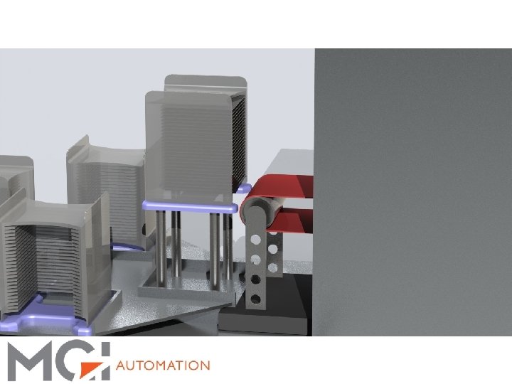
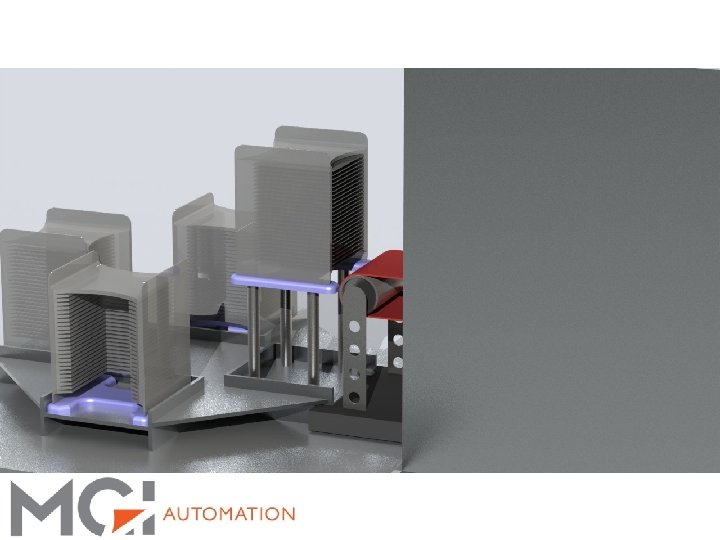
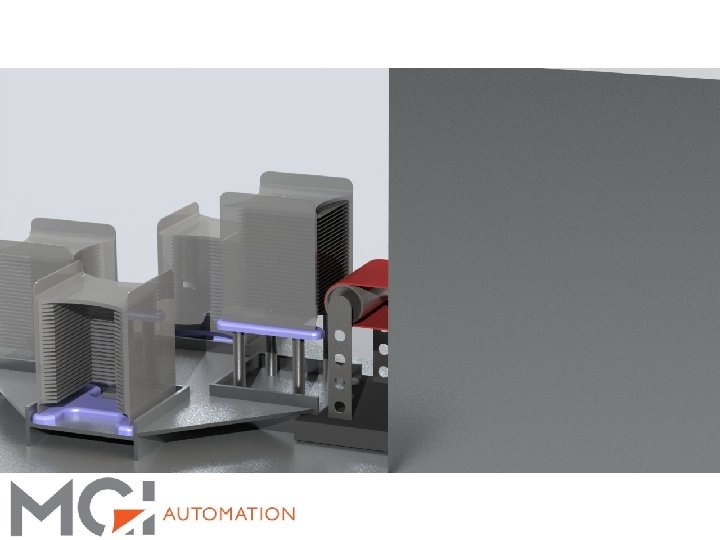
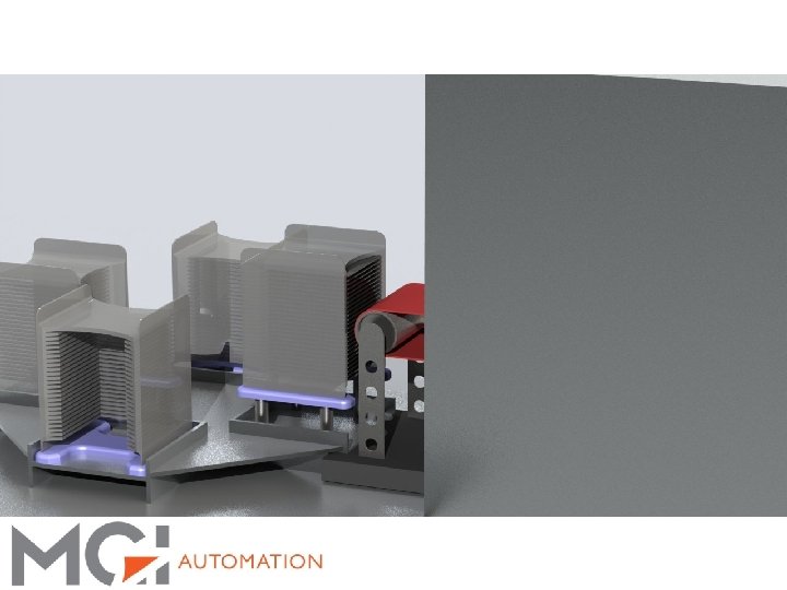
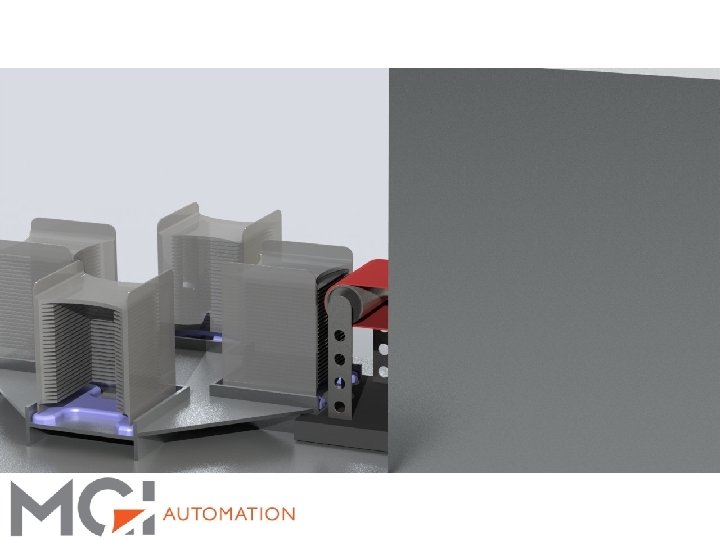
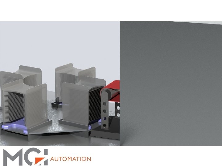
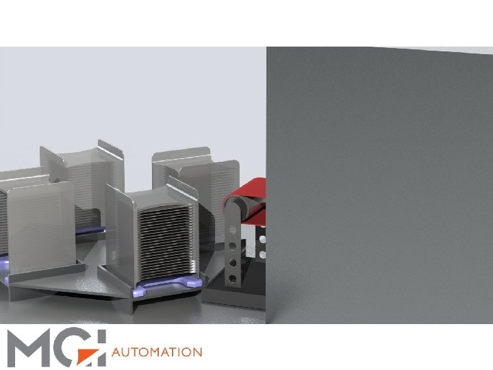
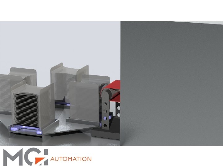
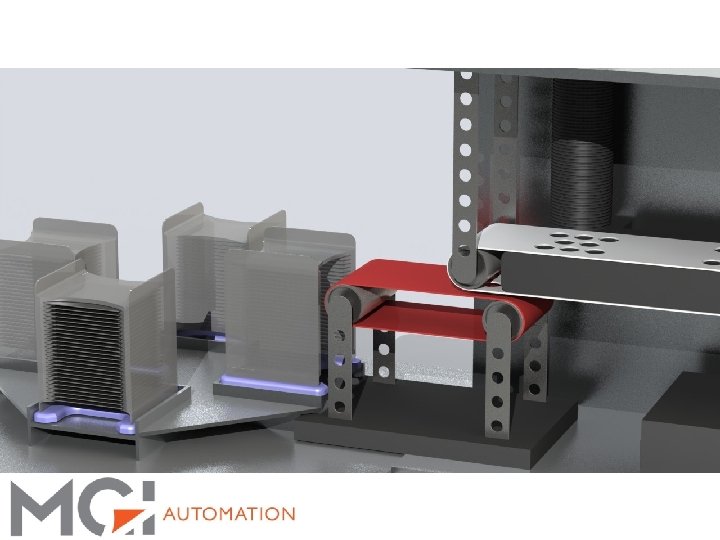

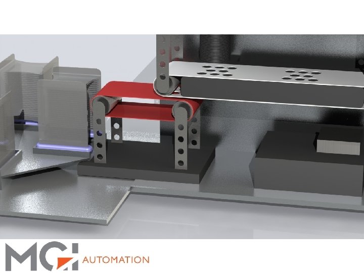

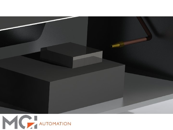
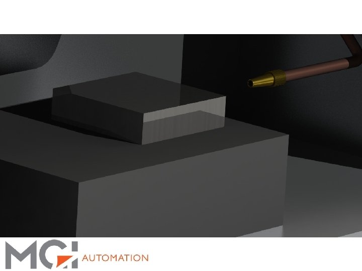
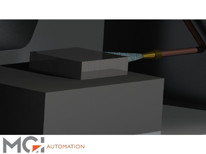
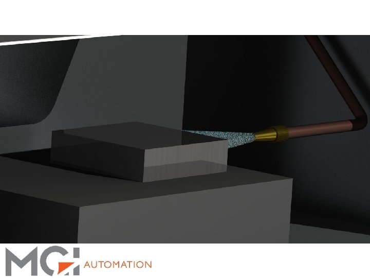
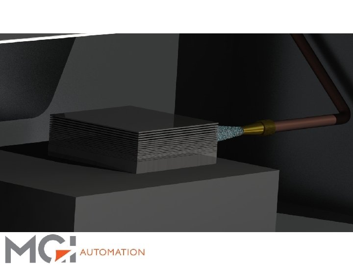
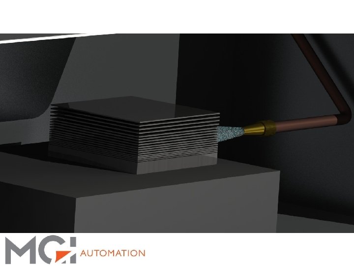
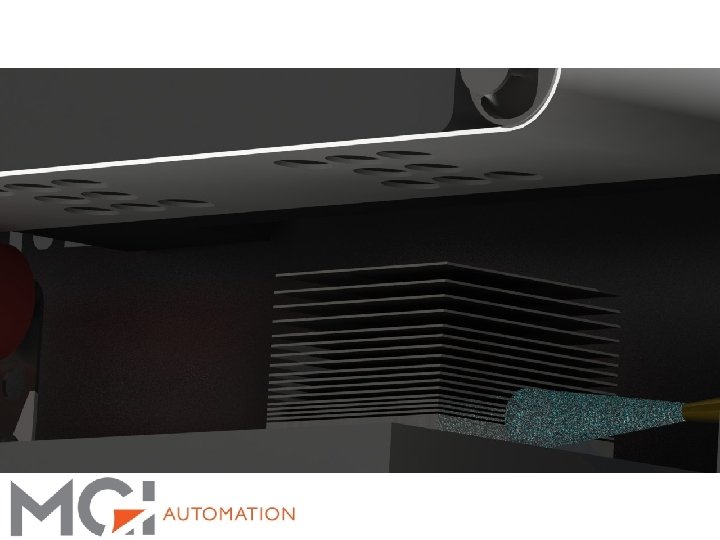
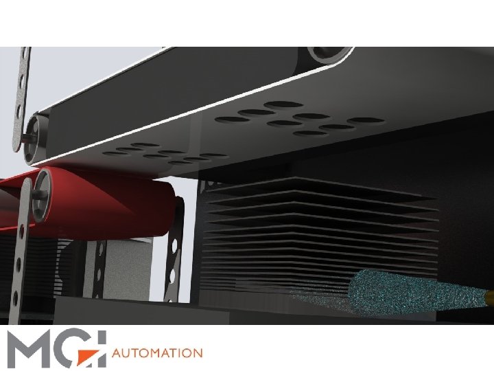
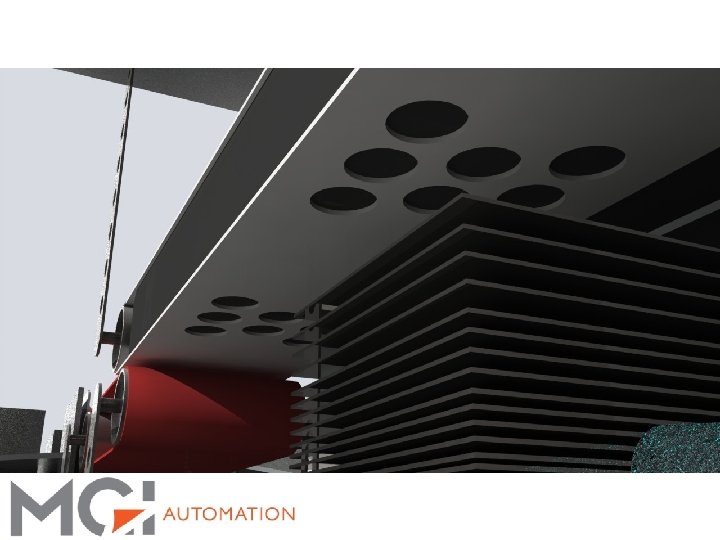
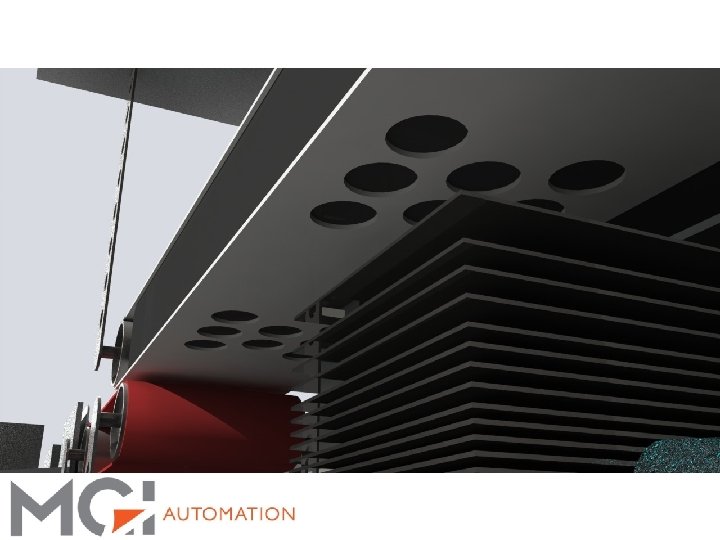
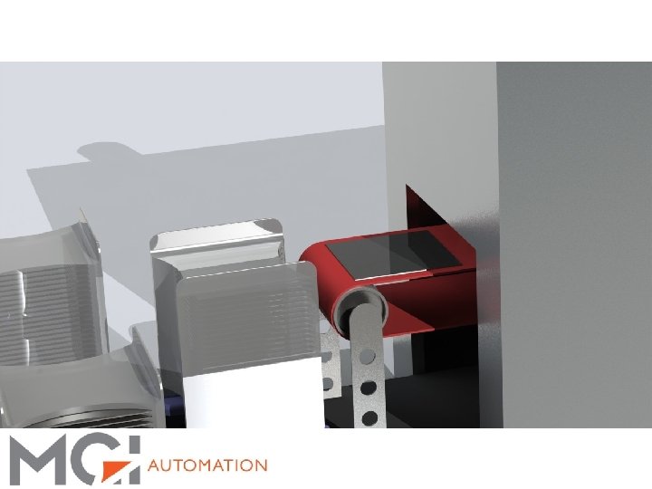
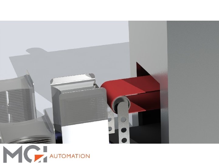
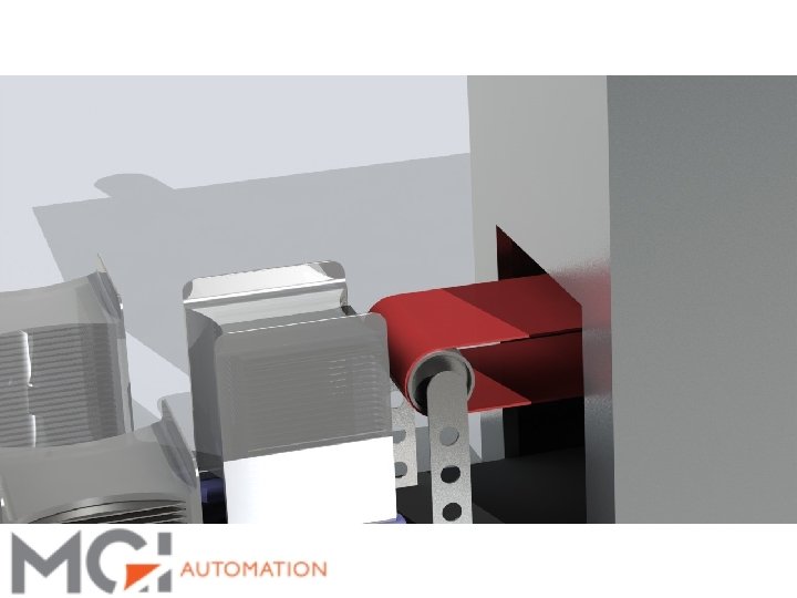
3 S Visualization: Wet Separation: § Water is introduced to separate the stack of wafers § This process is illustrated below
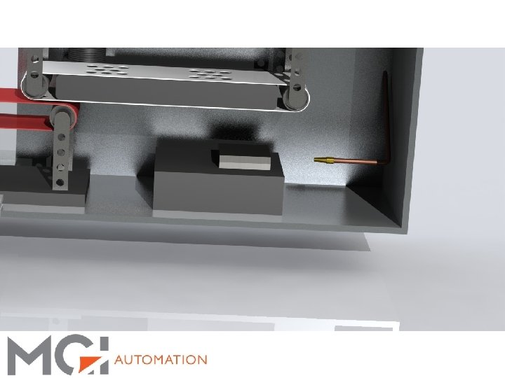
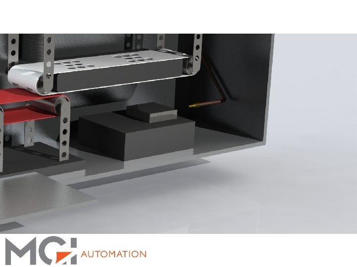
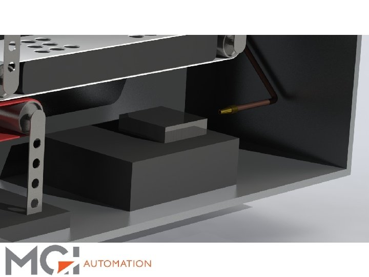

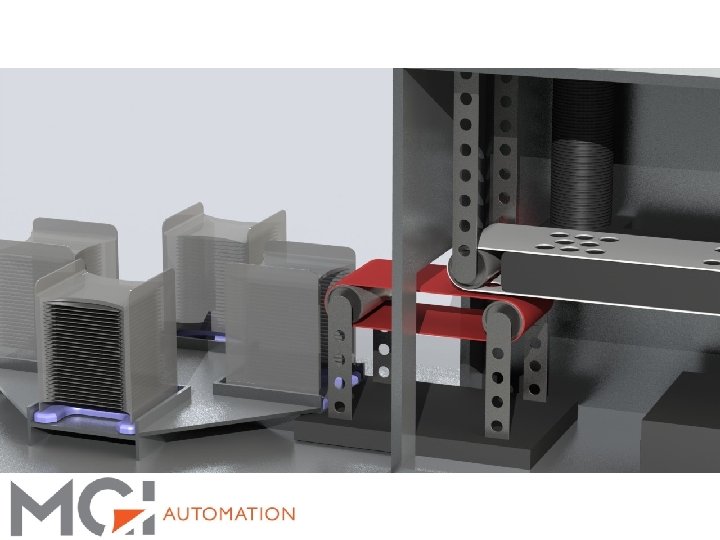
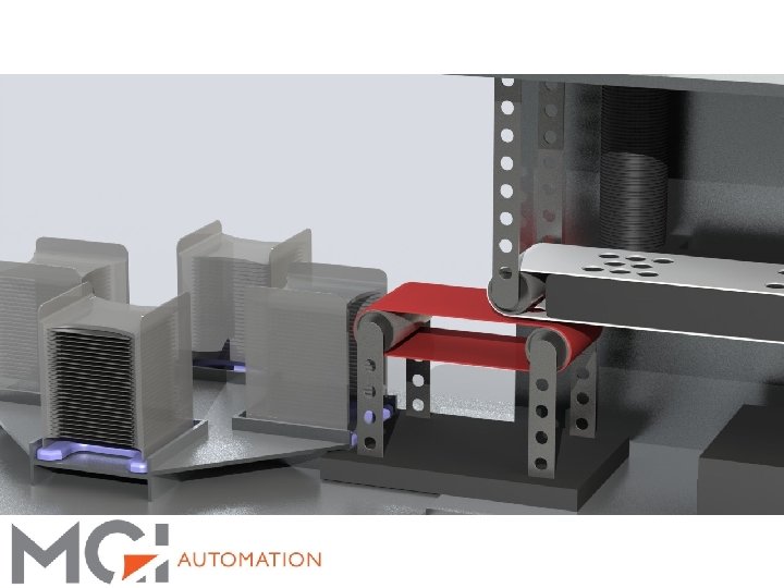
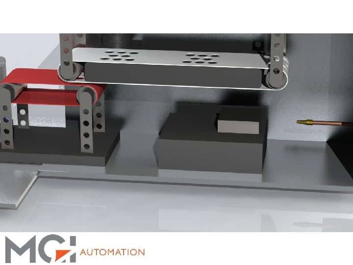
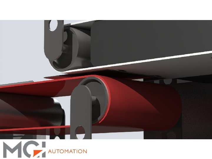
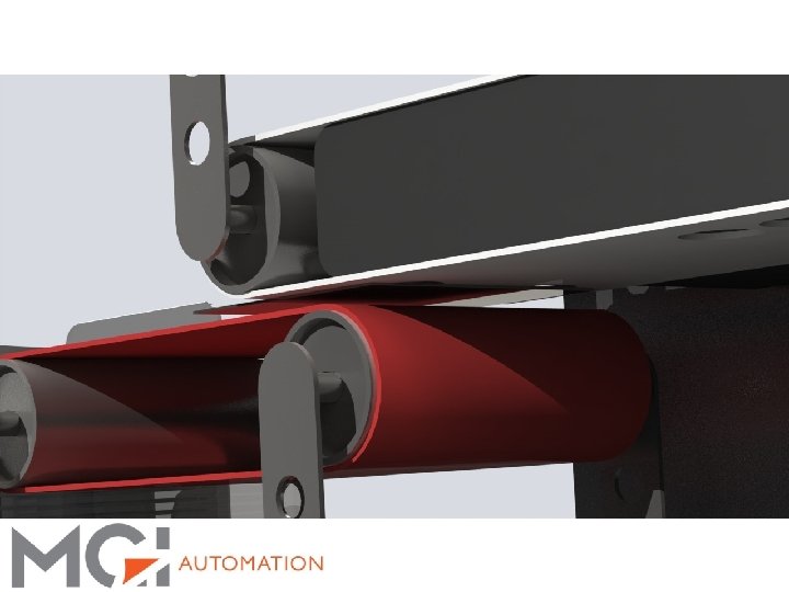
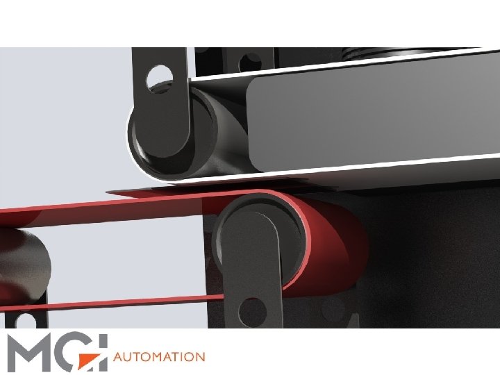
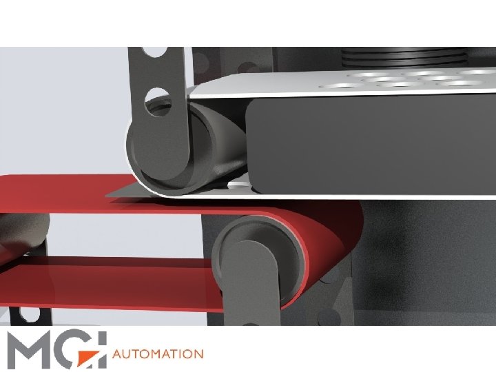
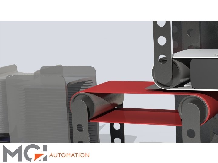
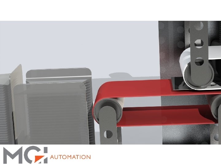
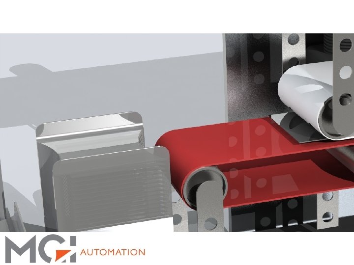
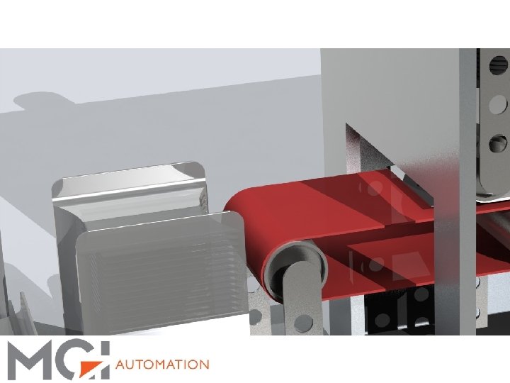
3 S Visualization: Vacuum Belt Concept: § After the stack is sufficiently separated, a vacuum belt gently lifts the top wafer to carry it to the loading belt


3 S Visualization: Wafer Loading: § Wafers are then loaded into cassettes, as shown in the beginning of the presentation


Thank you for your time! For questions or more information, please contact us at: North American Sales Diane Butler dbutler@mgiautomation. com 480. 436. 5026 ext. 4005 480. 622. 9250 – cell European Sales George Rhoades grhoades@mgiautomation. com 480. 436. 5026 ext. 4006 480. 283 -5602 – cell Far East Sales Curt Butler cbutler@mgiautomation. com 480. 436. 5026 ext. 4001 602. 538. 6055 – cell General Contact MGI Automation, LLC 2715 #103 South Hardy Drive Tempe, Arizona 85282 480. 436. 5026 – office
- Slides: 79