Intro to Movement of robots and introduction to

Intro to Movement of robots and introduction to kinematics of robots

• Kinematics: constraints on getting around the environment kinematics The effect of a robot’s geometry on its motion. wheeled platforms from sort of simple to sort of difficult manipulator modeling

Effectors and Actuators • An effector is any device that affects the environment. • A robot's effector is under the control of the robot. • Effectors: – – legs, wheels, arms, fingers. • The role of the controller is to get the effectors to produce the desired effect on the environment, – this is based on the robot's task.

Effectors and Actuators • An actuator is the actual mechanism that enables the effector to execute an action. • Actuators typically include: include – – electric motors, hydraulic cylinders, pneumatic cylinders, etc. • The terms effector and actuator are often used interchangeably to mean "whatever makes the robot take an action. " • This is not really proper use: – Actuators and effectors are not the same thing. – And we'll try to be more precise.
")
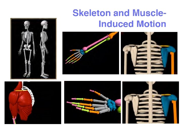
Kinematics for Animals (and humans)

Review: degrees of freedom • Most simple actuators control a single degree of freedom, • i. e. , a single motion (e. g. , up-down, left-right, in-out, etc. ). – A motor shaft controls one rotational degree of freedom, for example. – A sliding part on a plotter controls one translational degree of freedom. • How many degrees of freedom (DOF) a robot has is very important in determining how it can affect its world, – and therefore how well, if at all, it can accomplish its task. • We said many times before that sensors must be matched to the robot's task. • Similarly, effectors must be well matched to the robot's task also. When you design a robot your first task is decide the number of DOF and the geometry.

DOF • In general, a free body in space as 6 DOF: – three for translation (x, y, z), – three for orientation/rotation (roll, pitch, and yaw). • You need to know, for a given effector (and actuator/s): – how many DOF are available to the robot, – how many total DOF any given robot has. • If there is an actuator for every DOF, then all of the DOF are controllable. • Usually not all DOF are controllable, which makes robot control harder. To demonstrate, use a pen in your hand…. .
")
DOF and controllable DOFs • A car has 3 DOF: – position (x, y) and – orientation (theta). • But only 2 DOF are controllable: – driving: through the gas pedal and the forward-reverse gear; – steering: through the steering wheel. • Since there are more DOF than are controllable, there are motions that cannot be done. • Example of such motions is moving sideways (that's why parallel parking is hard).

DOF for animals

One Minute Test • How many degrees of freedom does your hand have, with your forearm fixed in position? • (Hint: It’s not 6) Answer on next slide

Degrees of Freedom in Hand Part Wrist Palm Fingers Thumb Total Do. F Comment 2 1. Side-to-side 2. Up-down 1 1. Open-close a little 4*4 1. 2. 23 2 @ base (Up-down & side-to-side) 1 @ each of two joints 2 @ base (attached to wrist) 2 @ visible joints Hand has 23 degrees of freedom
")
Total and Controllable DOFs • Kinematics: y wheeled platforms vs. robot arms (or legs) x VL VR • We need to make a distinction between what an actuator does (e. g. , pushing the gas pedal) and what the robot does as a result (moving forward). • A car can get to any 2 D position but it may have to follow a very complicated trajectory. • Parallel parking requires a discontinuous trajectory with respect to the velocity. • It means that the car has to stop and go.

What is a HOLONOMIC robot?

Definition of a HOLONOMIC robot • When the number of controllable DOF is equal to the total number of DOF on a robot, the robot is called holonomic. (i. e. the hand built by Uland Wong). Holonomic <= > Controllable DOF = total DOF

DOF versus types of robots Non-Holonomic <= > Controllable DOF < total DOF • If the number of controllable DOF is smaller than total DOF, the robot is non-holonomic. • If the number of controllable DOF is larger than the total DOF, the robot is redundant. (like a human hand, we did not build such robot yet) Redundant <= > Controllable DOF > total DOF

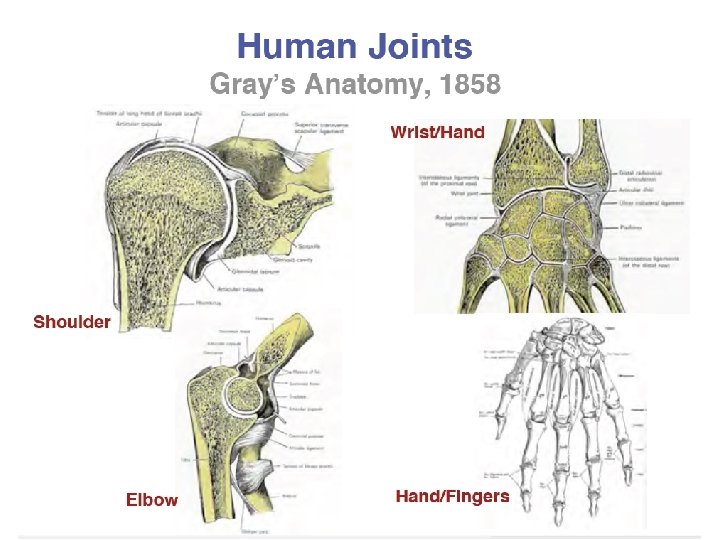
DOF for animals • A human arm has 7 DOF: – 3 in the shoulder, – 1 in the elbow, – 3 in the wrist • All of which can be controlled. • A free object in 3 D space (e. g. , the hand, the finger tip) can have at most 6 DOF! • So there are redundant ways of putting the hand at a particular position in 3 D space. • This is the core of why robot manipulation is very hard! One minute test!
-tall and 4.")
JAPAN HONDA AND SONY ROBOTS • Pino, a 70 -centimeter (2 -foot)-tall and 4. 5 -kilogram (9 -pound) humanoid robot designed by Japan Science and Technology Corporation in Tokyo which can walk on its legs and respond to stimulation through a sensor, shakes hand with Malaysia's Prime Minister Mahathir Mohamad during the opening of the Expo Science & Technology 2001 in Kuala Lumpur, Malaysia, Monday, July 2, 2001. (AP Photo/Andy Wong) Question: how many DOF?
 • This is in any case simplified")
98 degrees (of freedom) • This is in any case simplified

Anatomical Coordinates and Robots that mimick animals

Human Anatomical Coordinates – important in work on humanoid robots • Sagittal Plane • Coronal Plane • Transverse Plane

Animal Anatomical Coordinates • We built robot fishes, horses, dogs and other animals.

Prosthetic Arms and Hands

Knowledge of bio-mechanics is useful to design hands, necks, heads for animatronic robots

Types of kinematic Systems

Robot Arms for Space, All kinds of manipulators

Robot Arms for Space

Serial Robotic Manipulators

Serial Robotic Manipulators • Serial chain of robotic links and joints. – Large workspace – Low stiffness – Cumulative errors from link to link • • • Proximal Link – closer to the base Distal Link – farther from the base Proximal links carry the weight and load of distal links Actuation of proximal joints affects distal links. Limited load-carrying capability at the end effector.


Parallel Robotic Mechanisms

Parallel Robotic Mechanisms • End plate is directly actuated by multiple links and joints. • Multiple links and joints are called a kinematic chain. • The workspace is restricted • Common link-joint configuration • This can serve as Pick-and-Place Robot • Light construction • Stiffness • High load-carrying capacity. • We use it for waist in MCECS BOT.

Manipulation

Manipulation
, the body of the robot is moved to")
Manipulation • In locomotion (mobile robot), the body of the robot is moved to get to a particular position and orientation. • In contrast - a manipulator moves itself – typically to get the end effector (e. g. , the hand, the fingertip) – to the desired 3 D position and orientation. • So imagine having to touch a specific point in 3 D space with the tip of your index finger; – that's what a typical manipulator has to do.

Issues in Manipulation • In addition: manipulators need to: – grasp objects, – move objects. – But those tasks are extensions of the basic reaching discussed above. • The challenge is to get there efficiently and safely. • Because the end effector is attached to the whole arm, we have to worry about the whole arm: – the arm must move so that it does not try to violate its own joint limits, – it must not hit itself or the rest of the robot, or any other obstacles in the environment.

Manipulation - Teleoperation • Thus, doing autonomous manipulation is very challenging. • Manipulation was first used in tele-operation, where human operators would move artificial arms to handle hazardous materials. • Complicated duplicates of human arms, with 7 DOF were built. • It turned out that it was quite difficult for human operators to learn how to tele-operate such arms

Manipulation and Teleoperation: Human Interface • One alternative today is to put the human arm into an exo-skeleton, in order to make the control more direct. • Using joy-sticks, for example, is much harder for high DOF. Exo-skeletons used in “Hollywood Robotics”

Why is using joysticks so hard? • Because even as we saw with locomotion, there is typically no direct and obvious link between: – what the effector needs to do in physical space – and what the actuator does to move it. • In general, the correspondence between actuator motion and the resulting effector motion is called kinematics. • In order to control a manipulator, we have to know its kinematics: – 1. what is attached to what, – 2. how many joints there are, – 3. how many DOF for each joint, – etc.

Basic Problems for Manipulation • Kinematics · Given all the joint angles - where is the tip ? • Inverse Kinematics · Given a tip position - what are the possible joint angles ? • Dynamics · To accelerate the tip by a given amount how much torque should a particular joint motor put out ?

Kinematics versus Inverse Kinematics • We can formalize all of this mathematically. – To get an equation which will tell us how to convert from, say, angles in each of the joints, to the Cartesian positions of the end effector/point is called: • computing the manipulator kinematics – The process of converting the Cartesian (x, y, z) position into a set of joint angles for the arm (thetas) is called: • inverse kinematics. Something for lovers of math and programming! Publishable! LISP

Manipulators
 connected by joints –")
Manipulators • Robot arms, industrial robot – Rigid bodies (links) connected by joints – Joints: revolute or prismatic – Drive: electric or hydraulic – End-effector (tool) mounted on a flange or plate secured to the wrist joint of robot

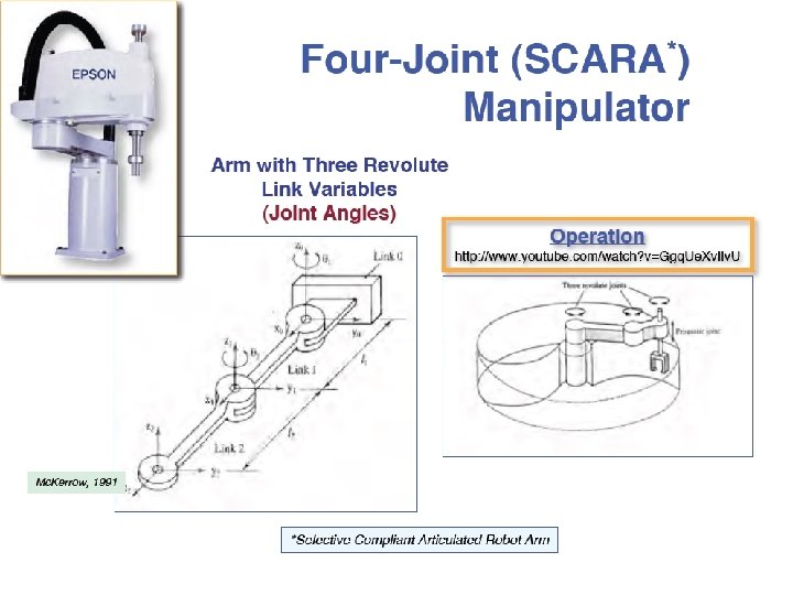
Manipulators: Robot Configurations Cartesian: PPP Cylindrical: RPP Spherical: RRP Hand coordinate: Articulated: RRR SCARA: RRP n: normal vector; s: sliding vector; (Selective Compliance Assembly Robot Arm) a: approach vector, normal to the tool mounting plate 47

Manipulators: Motion Control Methods – Point to point control • a sequence of discrete points • spot welding, pick-and-place, loading & unloading – Continuous path control • follow a prescribed path, controlled-path motion • Spray painting, Arc welding, Gluing
 => Position")
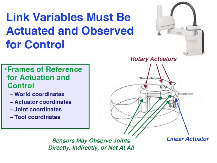
Manipulators: Robot Specifications – Number of Axes • Major axes, (1 -3) => Position the wrist • Minor axes, (4 -6) => Orient the tool • Redundant, (7 -n) => reaching around obstacles, avoiding undesirable configuration – – Degree of Freedom (DOF) Workspace Payload (load capacity) Precision v. s. Repeatability Which one is more important?

Joints. • Joints connect parts of manipulators. • The most common joint types are: • Prismatic Link – revolute link (rotation around a fixed axis) – prismatic link (linear movement) These joints provide the DOF for an effector.

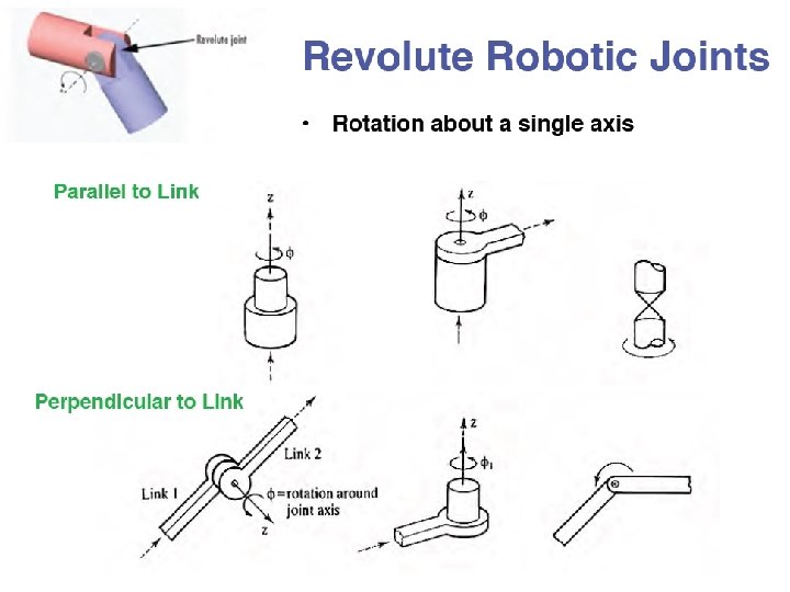
Joints. Revolute Link

Revolute Robotic Joints

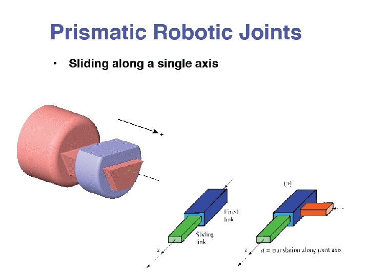
Prismatic Robotic Joints

Other Robotic Joints


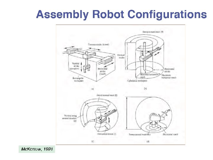
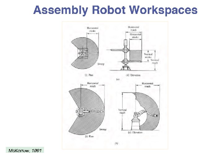
Assembly Robot Configurations and Workspaces

• • Terms for manipulation Links and joints End effector, tool Accuracy vs. Repeatability Workspace Reachability Manipulability Redundancy Configuration Space

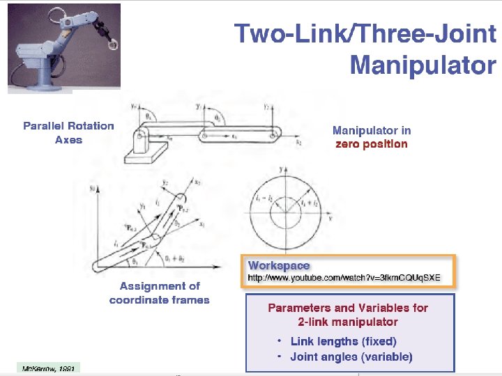
Types of Manipulators Basic distinction: what kinds of joints extend from base to end. “RR” or “ 2 R” “PR” arm All manipulators can be represented as chains of P (prismatic) and R (rotational) joints.

Prismatic Joints Ninja Ambler tomato harvester

Challenges in kinematics design 1. Modeling many degrees of freedom 2. No closed-form solution guaranteed for the inverse kinematics. 3. Trajectory generation under nonholonomic constraints 4. Navigating with obstacles obstacle goal
 for a task.")
Challenges: multiple solutions Multiple solutions (or no solutions) for a task.
 for a task.")
Challenges Multiple solutions (or no solutions) for a task.

Opportunities • Direct kinematic/ inverse kinematic modeling - is the basis for control of the vast majority of industrial robots. • Accurate (inverse) kinematic models are required in order to create believable character animations how would these things bike?

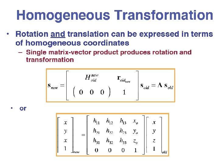
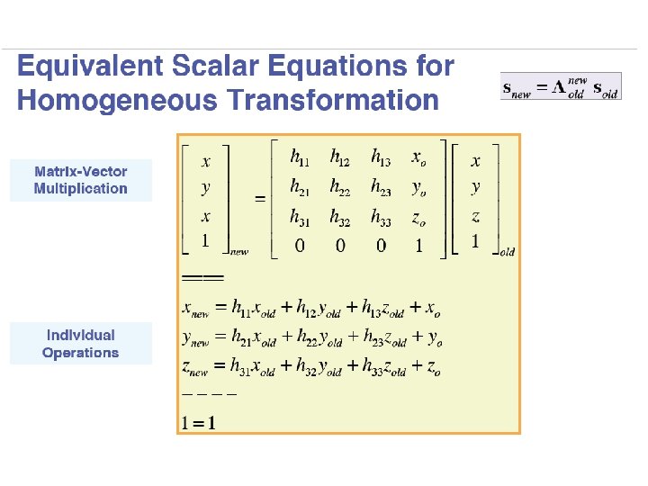
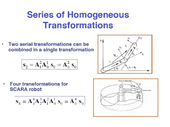
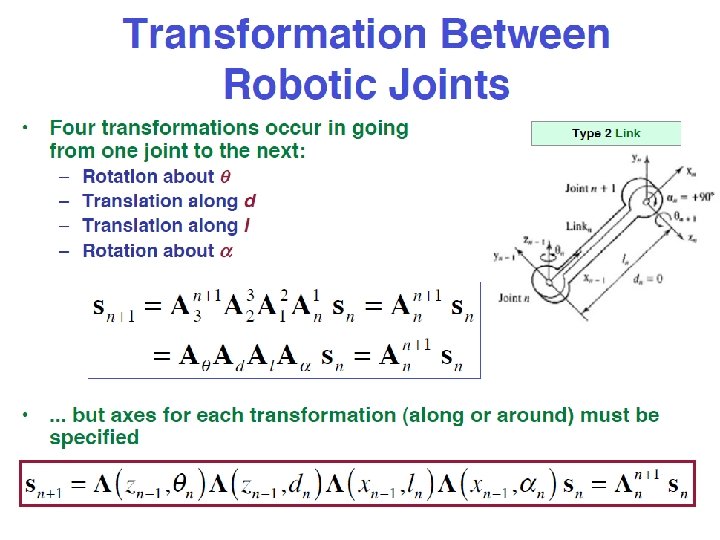
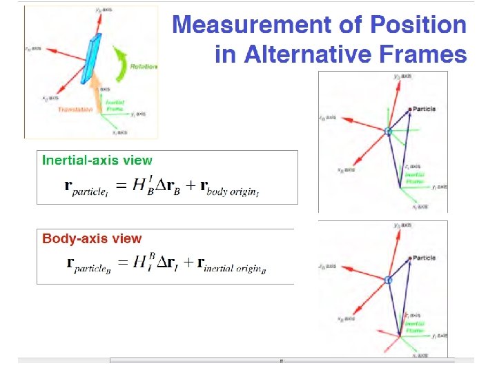
Homogeneous Transformation
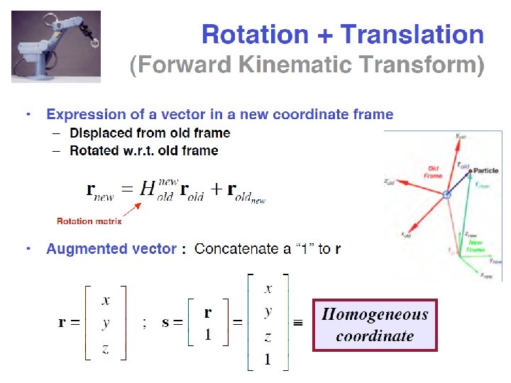

Homogeneous Transformation

Examples of Manipulators

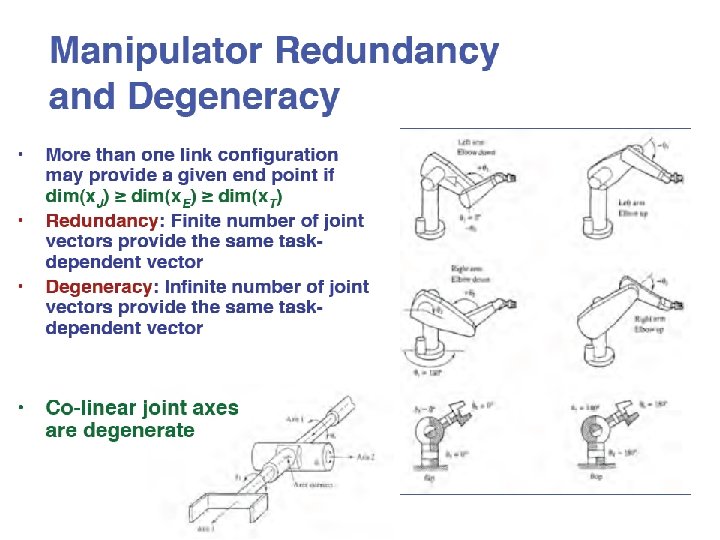
Manipulator Redundancy and Degeneracy


Sources • • Robert Stengel Prof. Maja Mataric Dr. Fred Martin Bryce Tucker and former PSU students A. Ferworn, Prof. Gaurav Sukhatme, USC Robotics Research Laboratory Paul Hannah • Reuven Granot, Technion • Dodds, Harvey Mudd College
- Slides: 88