Intro Light Propagation in Free Space Helmholtz Equation


 Holography • In 1948, Dennis Gabor introduced “A new microscopic principle”, 1")


 Holography or Phase Conjugation • Clearly, the field emerging from the")


- Slides: 53
Intro
Light Propagation in Free Space • Helmholtz Equation • 1 -D Propagation • Plane waves
Plane wave propagation
Light Propagation in Free Space • 3 -D Propagation • Spherical Waves
Huygen’s Principle • Each point reached by the field becomes a secondary source, which emits a new spherical wavelet and so on. • Generally this integral is hard to evaluate
Fresnel Approximation of Wave Propagation • The spherical wavelet at far field is now approximated by
Fresnel Approximation of Wave Propagation • For a given planar field distribution at z = 0, U(u, v), we can calculate the resulting propagated field at distance z, U(x, y, z) by convolving with the Fresnel wavelet
Fourier Transform Properties of Free Space • Fraunhofer approximation is valid when the observation plane is even farther away. And the quadratic phase becomes • The field distribution then is described as a Fourier transform
Fourier Transform Properties of Lenses • Lenses have the capability to perform Fourier Transforms, eliminating the need for large distances of propagation. • Transmission function in the form of
Fourier Transform Properties of Lenses
Fourier Transform Properties of Lenses • Fourier transform of the field diffracted by a sinusoidal grating.
Chap. 5 Light Microscopy
Abbe’s Theory of Imaging • One way to describe an imaging system (e. g. , a microscope) is in terms of a system of two lenses that perform two successive Fourier Transforms. • Magnification is given by • Cascading many imaging systems does not mean unlimited resolution!
Resolution Limit • ‘’The microscope image is the interference effect of a diffraction phenomenon” – Abbe, 1873 • The image field can therefore be decomposed into sinusoids of various frequencies and phase shifts
Resolution Limit • the apertures present in the microscope objective limit the maximum angle associated with the light scattered by the specimen. • The effect of the objective is that of a low-pass filter, with the cut-off frequency in 1 D given by
Resolution Limit • The image is truncated by the pupil function at the frequency domain • The resulting field is then the convolution of the original field and the Fourier Transform of P
Resolution Limit • function g is the Green’s function or PSF of the instrument, and is defined as • The Rayleigh criterion for resolution: maxima separated by at least the first root. • Resolution:
Imaging of Phase Objects •
Dark Field Microscopy • One straightforward way to increase contrast is to remove the low-frequency content of the image, i. e. DC component, before the light is detected. • For coherent illumination, this high pass operation can be easily accomplished by placing an obstruct where the incident plane wave is focused on axis.
Zernike’s Phase Contrast Microscopy •
Zernike’s Phase Contrast Microscopy •
Zernike’s Phase Contrast Microscopy •
Zernike’s Phase Contrast Microscopy
Chap. 6 Holography
Gabor’s (In-Line) Holography • In 1948, Dennis Gabor introduced “A new microscopic principle”, 1 which he termed holography (from Greek holos, meaning “whole” or “entire, ” and grafe, “writing”). • Record amplitude and phase • Film records the Interference of light passing through a semitransparent object consists of the scattered (U 1) and unscattered field (U 0).
In-line Holography • Reading the hologram essentially means illuminating it as if it is a new object (Fig. 6. 2). The field scattered from the hologram is the product between the illuminating plane wave (assumed to be ) and the transmission function • The last two terms contain the scattered complex field and its backscattered counterpart. The observer behind the hologram is able to see the image that resembles the object. • The backscattering field forms a virtual image that overlaps with the focused image.
Off-Axis Holography • Emmitt Leith and Juris Upatnieks developed this off-axis reference hologram, the evolution from Gabor’s inline hologram. • Writing the hologram: • The field distribution across the film, i. e. the Fresnel diffraction pattern is a convolution between the transmission function of the object U, and the Fresnel kernel • The resulting transmission function associated with the hologram is proportional to the intensity, i. e.
Off-Axis Holography •
Nonlinear (Real Time) Holography or Phase Conjugation • Clearly, the field emerging from the material, U 4, is the timereversed version of U 3, i. e. ω4 = -ω3 and k 4 = -k 3, as indicated by the complex conjugation (U 3∗).
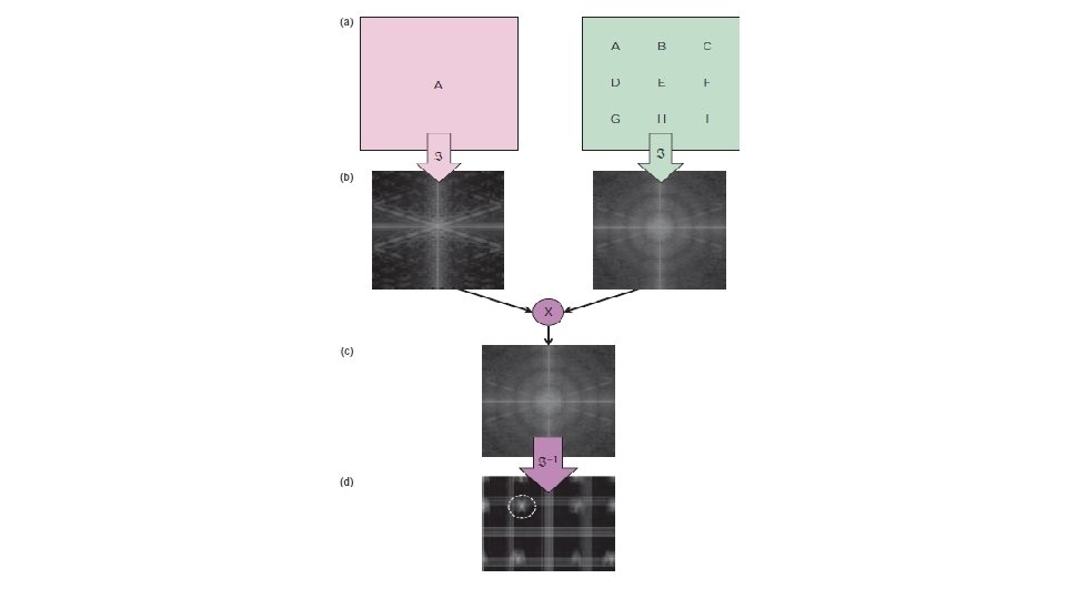
Digital Hologram writing • idea is to calculate the cross-correlation between the known signal of interest and an unknown signal which, as a result, determines (i. e. , recognizes) the presence of the first in the second • The result field on the image plane is characterized by the cross correlation between the image in interest and the image being compared
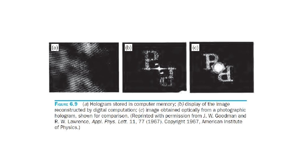
Digital Holography reading • The transparency containing the signal of interest is illuminating by a plane wave. The emerging field, U 0, is Fourier transformed by the lens at its back focal plane, where the 2 D detector array is positioned. The off-axis reference field Ur is incident on the detector at an angle θ. • Fourier Transforms are numerically processed with FFT algorithm
Chap. 8 Principles of Full-Field QPI
Interferometric Imaging •
Temporal Phase Modulation: Phase-Shifting Interferometry • The idea is to introduce a control over the phase difference between two interfering fields, such that the intensity of the resulting signal has the form
Temporal Phase Modulation: Phase-Shifting Interferometry •
Temporal Phase Modulation: Phase-Shifting Interferometry
Spatial Phase Modulation: Off-Axis Interferometry • Off-axis interferometry takes advantage of the spatial phase modulation introduced by the angularly shifted reference plane wave
Spatial Phase Modulation: Off-Axis Interferometry •
Phase Unwrapping •
Figures of Merit in QPI • Temporal Sampling: Acquisition Rate • Must be at least twice the frequency of the signal of interest, according to Nyquist sampling theorem. • In QPI acquisition rate vary from application: from >100 Hz in the case of membrane fluctuations to <1 m. Hz when studying the cell cycle. • Trade-off between acquisition rate and sensitivity. • Off-axis has the advantage of “single shot” over phase-shifting techniques, which acquires at best four time slower than that of the camera.
Figures of Merit in QPI • Spatial Sampling: Transverse Resolution • QPI offer new opportunities in terms of transverse resolution, not clear -cut in the case of coherent imaging. • The phase difference between the two points has a significant effect on the intensity distribution and resolution. • Phase shifting methods are more likely than phase shifting method to preserve the diffraction limited resolution
Figures of Merit in QPI • Temporal Stability: Temporal-Phase Sensitivity • Assess phase stability experimentally: perform successive measurements of a stable sample and describe the phase fluctuation of one point by its standard deviation
Figures of Merit in QPI • Temporal Stability: Temporal-Phase Sensitivity Reducing Noise Level: • Simple yet effective means is to reference the phase image to a point in the field of view that is known to be stable. This reduces the common mode noise, i. e. phase fluctuations that are common to the entire field of view. • A fuller descriptor of the temporal phase noise is obtained by computing numerically the power spectrum of the measured signal. The area of the normalized spectrum gives the variance of the signal
Figures of Merit in QPI •
Figures of Merit in QPI • Temporal Stability: Temporal-Phase Sensitivity • • Passive stabilization Active stabilization Differential measurements Common path interferometry
Figures of Merit in QPI • Spatial Uniformity: Spatial Phase Sensitivity • Analog to the “frame-to-frame” phase noise, there is a “point-to-point” (spatial) phase noise affects measurements.
Figures of Merit in QPI • Spatial Uniformity: Spatial Phase Sensitivity • The standard deviation for the entire field of view, following the time domain definition: • The normalized spectrum density • Thus variance defined as
Figures of Merit in QPI • Spatial Uniformity: Spatial Phase Sensitivity • Again, phase sensitivity can be increased significantly if the measurement is band-passed around a certain spatial frequency • Spatial and Temporal power spectrum
Summary of QPI Approaches and Figures of Merit • There is no technique that performs optimally with respect to all figures of merit identified
Summary of QPI Approaches and Figures of Merit •
Summary of QPI Approaches and Figures of Merit •