Intraoral Projections Intraoral images can be divided into

Intraoral Projections

Intraoral images can be divided into three categories: Periapical projections, which show the entire length of the tooth and the surrounding bone Bitewing projections, which show only the crowns of teeth and the adjacent alveolar crests Occlusal projections, which show an area of teeth and bone larger than periapical images

A full-mouth radiographic series consists of periapical and bitewing projections
 •")
Projections for a Typical Full-Mouth Radiographic Series Anterior Periapical (Use No. 1 Receptor) • Maxillary central incisors: one projection • Maxillary lateral incisors: two projections • Maxillary canines: two projections • Mandibular central and lateral incisors: two projections • Mandibular canines: two projection
 •")
Projections for a Typical Full-Mouth Radiographic Series Posterior Periapical (Use No. 2 Receptor) • Maxillary premolars: two projections • Maxillary distomolar (as needed): two projections • Mandibular premolars: two projections • Mandibular distomolar (as needed): two projections
 • Premolars:")
Projections for a Typical Full-Mouth Radiographic Series Bitewing (Use No. 2 Receptor) • Premolars: two projections • Molars: two projections

Criteria of Quality Radiographs should record the complete areas of interest on the image Radiographs should have the least possible amount of distortion Images should have optimal density and contrast to facilitate interpretation

complete areas of interest on the image Periapical radiographs: full length of the roots and at least 2 mm of periapical bone area of the entire abnormality plus some surrounding normal bone Bitewing examinations: each posterior proximal surface at least once Overlap of adjacent proximal tooth surfaces should be less than one third of the enamel thickness

the least possible amount of distortion Most distortion is caused by improper angulation of the xray beam rather than by the curvature of the structures being examined or inappropriate positioning of the receptor
, the milliamperage")
optimal density and contrast Radiographic exposure settings, including peak kilovoltage (k. Vp), the milliamperage (m. A), and exposure time (s) are crucial parameters that influence density and contrast for both digital- and filmbased radiography

Periapical Radiography • Asses extent of dental caries • Detect presence and assess extent of periapical inflammation • Evaluate consequences of traumatic injuries to the teeth and alveolar bone • Assess periodontal bone loss • Evaluate root morphology

Periapical Radiography • Assess implant osseointegration and peri-implant bone loss • Evaluate unerupted and impacted teeth • Evaluate external and internal root resorption • Assess pulp morphology • Determine length of endodontic instrumentation during treatment
 the paralleling technique")
Two intraoral projection techniques are commonly used for periapical radiography: (1) the paralleling technique (2) the bisecting-angle technique. Both techniques can be applied to digitaland filmbased imaging
, complementary")
receptor any medium used to capture an image, including film, charge-coupled devices (CCDs), complementary metal oxide semiconductor (CMOS) sensors, or storage phosphor plates. The principles for making projection radiographs are the same for each of these receptor type

Paralleling Technique rightangle technique long-cone technique

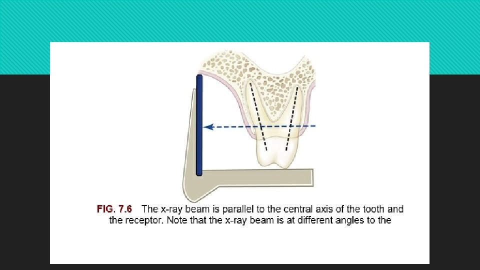
x-ray receptor parallel to the long axis of the teeth and the central ray of the x-ray beam is directed at right angles to the teeth and receptor minimizes geometric distortion and presents the teeth and supporting bone in their true anatomic relationships
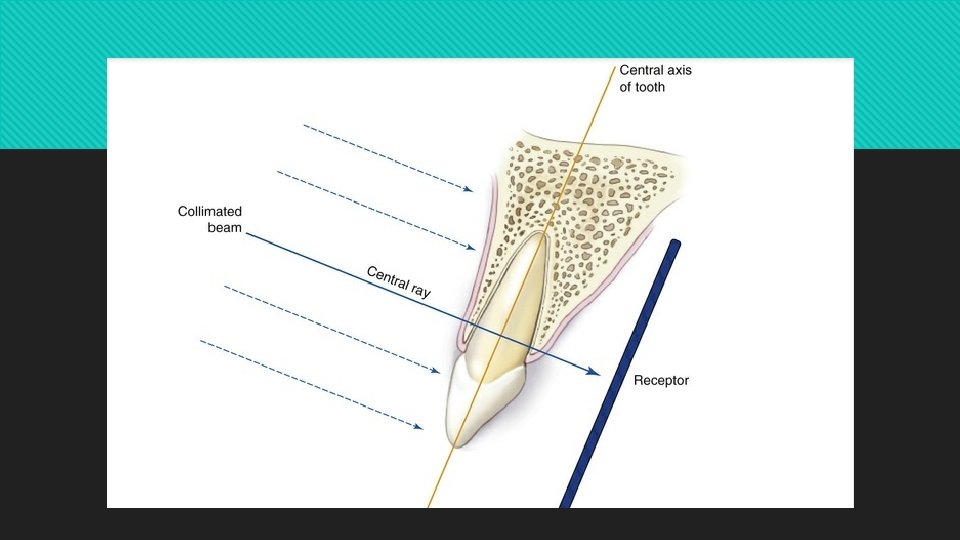

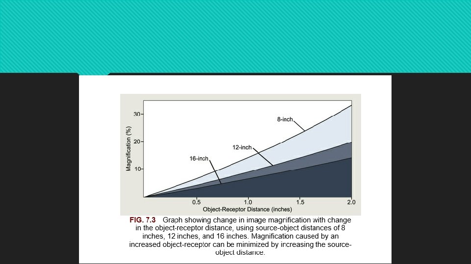
This increases the object-to-receptor distance and results in higher image magnification and poor geometric sharpness. To compensate for the resultant distortion and lack of sharpness, the paralleling technique is used with a relatively long source-to-object distance

Receptor-Holding Instruments

Receptor Placement parallel to the teeth deep into the lingual vestibule or palatal vault; For maxillary projections, the superior border of the receptor generally rests at the height of the palatal vault in the midline. for mandibular projections, the receptor should be used to displace the tongue posteriorly or toward the midline to allow the inferior border of the receptor to rest on the floor of the mouth away from the mucosa on the lingual surface of the mandible.

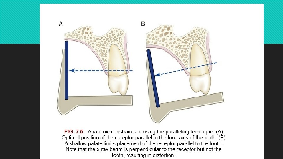
anatomic variations a shallow palate a shallow floor of the mouth, tori. all the roots of a multirooted tooth may not be placed parallel to the receptor, resulting indifferential distortion of the roots

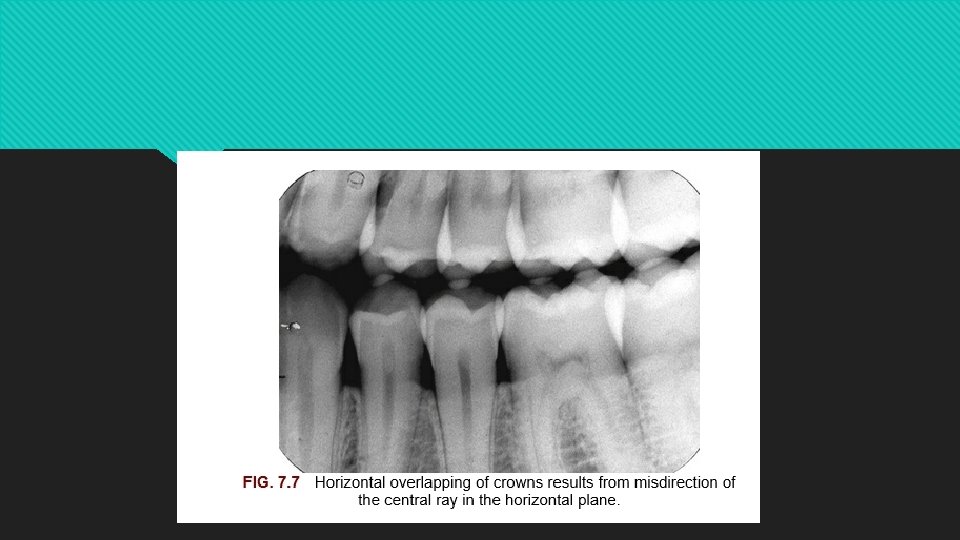
Angulation of the Tube Head to align with the aiming ring. The horizontal direction of the beam primarily influences the degree of overlapping of the images of the crowns at the interproximal space

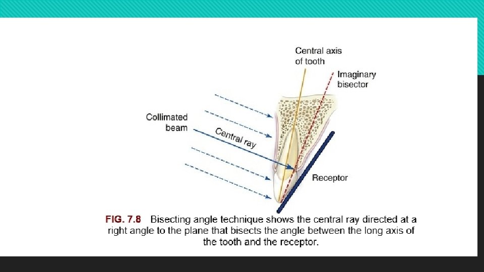
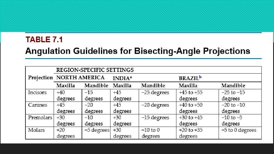
Bisecting Angle Technique Cieszynski's rule of isometry that two triangles are equal when they share one complete side and have two equal angles

Receptor-Holding Instruments receptorholding bisecting angle instrument forefinger

Positioning of the Patient Maxillary projections. The patient should be seated upright in the dental chair with the sagittal plane vertical and the occlusal plane horizontal. Mandibular projections. The patient should be seated upright in the dental chair with the sagittal plane vertical. The head is tilted back slightly to compensate for the changed occlusal plane when the mouth is opened

Receptor Placement behind the area of interest, with the apical end against the mucosa on the lingual or palatal surface The occlusal or incisal edge is oriented against the teeth with an edge of the receptor extending just beyond the teeth

Angulation of the Tube Head Horizontal angulation. Vertical angulation.

General Steps for Making Intraoral Radiographs Prepare unit for exposure Greet and seat the patient Adjust the x-ray unit setting Wash your hands thoroughly and wear appropriate personal protective equipment Examine the oral cavity Position the x-ray tube head Position the receptor Position the x-ray tube Make the exposure

Paralleling Technique

Maxillary Central Incisor Projection

Maxillary Lateral Projection

Maxillary Canine Projection

Maxillary Premolar Projection

Maxillary Molar Projection

Mandibular Centrolateral Projection

Mandibular Canine Projection

Mandibular Premolar Projection

Mandibular Molar Projection

Individual Periapical Projections A typical full-mouth radiographic series consists of 21 images start with the anterior views because they cause less discomfort for the patient.

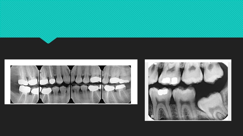
Bitewing Radiography interproximal radiographs the crowns of the maxillary and mandibular teeth and the alveolar crest on the same receptor.

Diagnostic Objectives of Bitewing Radiograph • Detect early interproximal caries before it becomes clinically apparent • Detect secondary caries below restorations • Assess loss of the interdental and furcation bone

Receptor Holding Instrument

Positioning of the Patient upright in the dental chair with the sagittal plane vertical and the occlusal plane horizontal

Angulation of the Tube Head Horizontal angulation. To effectively image the interproximal tooth surface without superimposition, the x-ray beam is directed through the contacts. Vertical angulation. about +10 degrees to project the beam parallel with the occlusal plan

Premolar Bitewing Projection

Molar Bitewing Projection

Occlusal Radiography An occlusal radiograph displays a relatively large segment of a dental arch. It may include the palate or floor of the mouth and a reasonable extent of the contiguous lateral structures

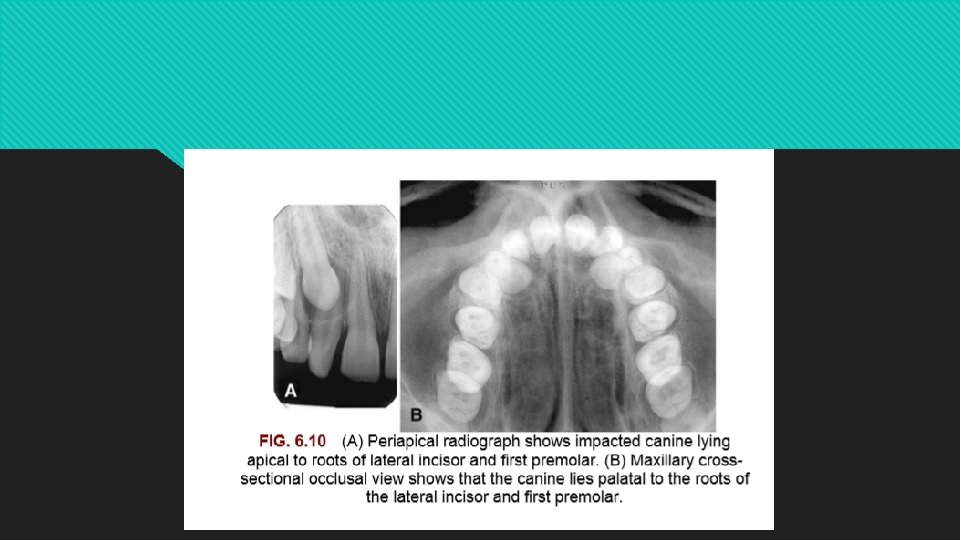
Diagnostic Objectives of Occlusal Radiography • To locate supernumerary, unerupted, and impacted teeth • To localize foreign bodies in the jaws and floor of the mouth • To identify and determine the full extent of disease (e. g. , cysts, osteomyelitis, malignancies) in the jaws, palate, and floor of the mouth • To evaluate and monitor changes in the midpalatal suture during orthodontic palatal expansion. To detect and locate sialoliths in the ducts of sublingual and submandibular glands

• To evaluate the integrity of the anterior, medial, and lateral outlines of the maxillary sinus • To aid in the examination of patients with trismus, who can open their mouths only a few millimeters • To obtain information about the location, nature, extent, and displacement of fractures of the mandible and maxilla

Occlusal receptors are made of film or storage phosphor plates. CCD or CMOS sensors of this size are not manufactured

Anterior Maxillary Occlusal Projection

Lateral Maxillary Occlusal Projection

Anterior Mandibular Occlusal Projection

Lateral Mandibular Occlusal Projection

Object Localization An inherent limitation of plain radiography is the twodimensional nature of the image.

Approaches to Decipher Three. Dimensional Relationships by Radiography • Examine two conventional images projected at right angles to each other. • Use the tube-shift technique employing conventional periapical views. • Image the anatomic region with a three-dimensional imaging modality.

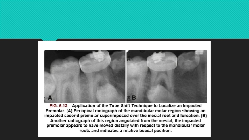
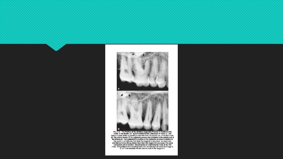
tube-shift technique buccal-object rule and Clark's rule When an object lies lingual to the reference object, its image appears to move in the direction of the tube shift.
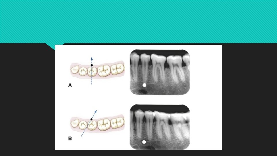

When the object lies buccal to the reference object, its image appears to move in the direction of opposite to the tube shift.
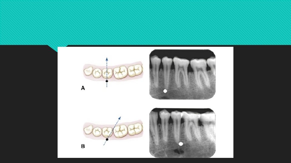

SLOB: same lingual, opposite buccal.

if the object in question appears to move in the same direction with respect to the reference structures as does the x-ray tube, it is on the lingual aspect of the reference object; if it appears to move in the opposite direction as the x-ray tube, it is on the buccal aspect

- Slides: 73