INTERRUPTS PROGRAMMING Interrupts vs Polling An interrupt is


 The program which is associated with the interrupt is")
 The advantage of interrupts is: ◦ The microcontroller can")
,")

 ◦ It gets the address of the")

 ◦ None")
 To enable an interrupt, we take the")
 is raised when the timer rolls over ◦")
 The microcontroller is interrupted in whatever it is doing, and")


 To ensure the activation of the hardware interrupt")


 When the ISRs are finished, TCON. 1 and TCON.")
 is raised when the stop bit is transferred")


")


- Slides: 48
INTERRUPTS PROGRAMMING
Interrupts vs. Polling An interrupt is an external or internal event that interrupts the microcontroller ◦ To inform it that a device needs its service A single microcontroller can serve several devices by two ways ◦ Interrupts Whenever any device needs its service, the device notifies the microcontroller by sending it an interrupt signal Upon receiving an interrupt signal, the microcontroller interrupts whatever it is doing
Interrupts vs. Polling (cont. ) The program which is associated with the interrupt is called the interrupt service routine (ISR) or interrupt handler ◦ Polling The microcontroller continuously monitors the status of a given device ex. JNB TF, target When the conditions met, it performs the service After that, it moves on to monitor the next device until every one is serviced Polling can monitor the status of several devices and serve each of them as certain conditions are met The polling method is not efficient, since it wastes much of the microcontroller’s time by
Interrupts vs. Polling (cont. ) The advantage of interrupts is: ◦ The microcontroller can serve many devices (not all at the same time) Each device can get the attention of the microcontroller based on the assigned priority For the polling method, it is not possible to assign priority since it checks all devices in a round-robin fashion ◦ The microcontroller can also ignore (mask) a device request for service This is not possible for the polling method
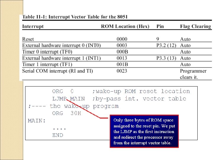
Interrupt Service Routine For every interrupt, there must be an interrupt service routine (ISR), or interrupt handler ◦ When an interrupt is invoked, the microcontroller runs the interrupt service routine ◦ There is a fixed location in memory that holds the address of its ISR The group of memory locations set aside to hold the addresses of ISRs is called interrupt vector table
Steps in Executing an Interrupt Upon activation of an interrupt, the microcontroller goes through: ◦ It finishes the instruction it is executing and saves the address of the next instruction (PC) on the stack ◦ It also saves the current status of all the registers internally (not on the stack) ◦ It jumps to a fixed location in memory, called the interrupt vector table, that holds the address of the ISR
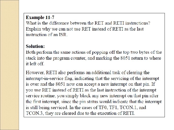
Steps in Executing an Interrupt (cont. ) ◦ It gets the address of the ISR from the interrupt vector table and jumps to ISR It starts to execute the interrupt service subroutine until it reaches the last instruction of the subroutine which is RETI (return from interrupt) ◦ Upon executing the RETI instruction, the microcontroller returns to the place where it was interrupted It gets the program counter (PC) address from the stack by popping the top two bytes of the stack into the PC It starts to execute from that address
Six Interrupts in 8051 Six interrupts are allocated as follows ◦ Reset – power-up reset ◦ Two interrupts are set aside for the timers: One for timer 0 and one for timer 1 ◦ Two interrupts are set aside for hardware external interrupts P 3. 2 and P 3. 3 are for the external hardware interrupts INT 0 (or EX 1), and INT 1 (or EX 2) ◦ Serial communication has a single interrupt that belongs to both receive and transfer
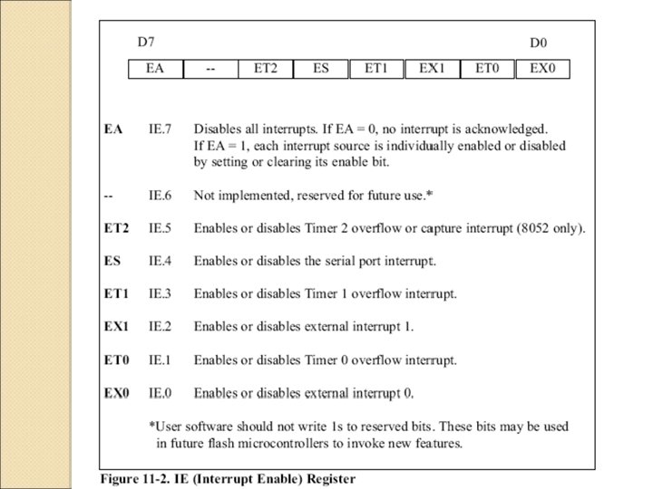
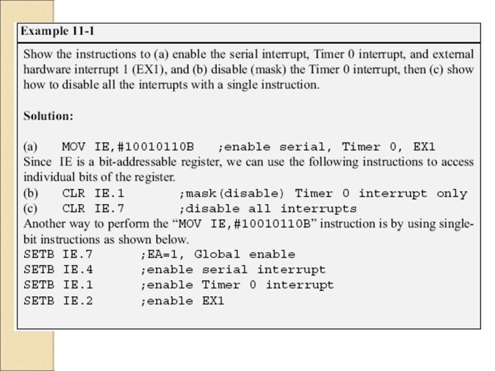
Enabling and Disabling an Interrupt Upon reset, all interrupts are disabled (masked) ◦ None will be responded to by the microcontroller if they are activated The interrupts must be enabled by software in order for the microcontroller to respond to them ◦ There is a register called IE (interrupt enable) that is responsible for enabling (unmasking) and disabling (masking) the interrupts
Enabling and Disabling an Interrupt (cont. ) To enable an interrupt, we take the following steps: ◦ Bit D 7 of the IE register (EA) must be set to high to allow the rest of register to take effect ◦ The value of EA If EA = 1, interrupts are enabled and will be responded to if their corresponding bits in IE are high If EA = 0, no interrupt will be responded to, even if the associated bit in the IE register is high
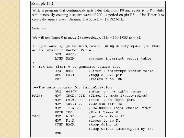
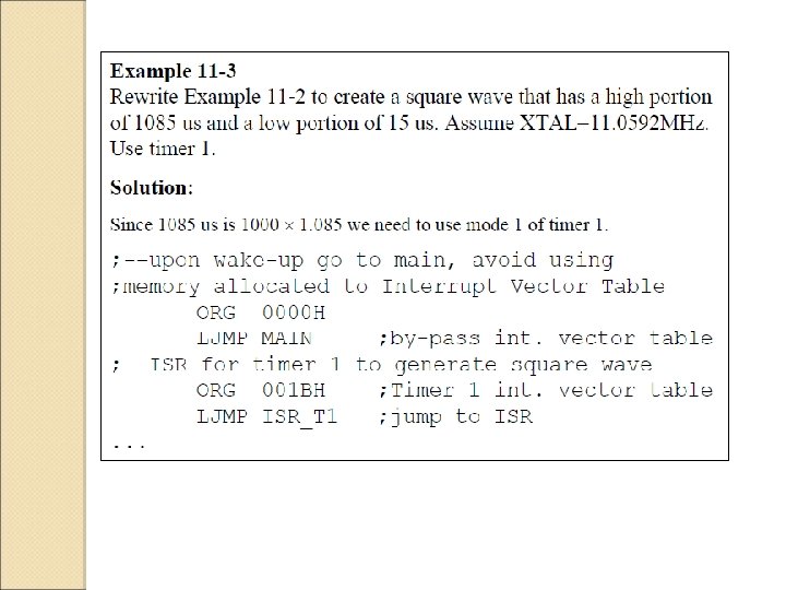
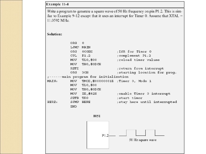
Timer Interrupts The timer flag (TF) is raised when the timer rolls over ◦ In polling TF, we have to wait until the TF is raised The microcontroller is tied down while waiting for TF to be raised, and can not do anything else ◦ Using interrupts to avoid tying down the controller If the timer interrupt in the IE register is enabled, whenever the timer rolls over, TF is raised
Timer Interrupts (cont. ) The microcontroller is interrupted in whatever it is doing, and jumps to the interrupt vector table to service the ISR In this way, the microcontroller can do other until it is notified that the timer has rolled over
SETB P 2. 1
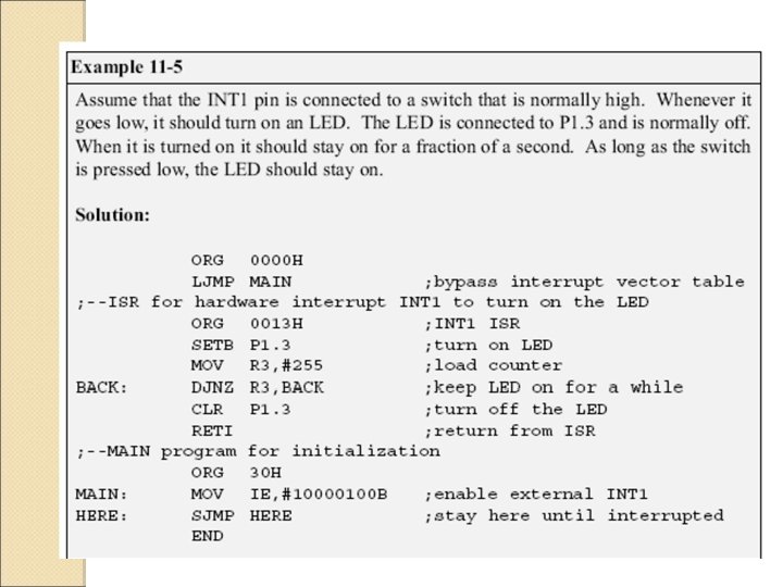
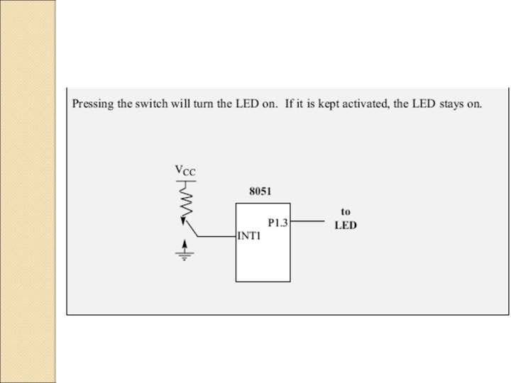
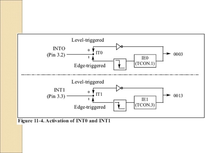
External Hardware Interrupts The 8051 has two external hardware interrupts ◦ Pin 12 (P 3. 2) and pin 13 (P 3. 3) of the 8051 Designated as INT 0 and INT 1 Used as external hardware interrupts ◦ The interrupt vector table locations 0003 H and 0013 H are set aside for INT 0 and INT 1 ◦ There are two activation levels for the external hardware interrupts Level trigged
Level-Triggered Interrupt INT 0 and INT 1 pins are normally high ◦ If a low-level signal is applied to them, it triggers the interrupt The microcontroller stops whatever it is doing and jumps to the interrupt vector table to service that interrupt The low-level signal at the INT pin must be removed before the execution of the last instruction of the ISR, RETI Otherwise, another interrupt will be generated This is called a level-triggered or levelactivated interrupt and is the default mode upon reset
Sampling Low Level-Triggered Interrupt P 3. 2 and P 3. 3 are used for normal I/O ◦ Unless the INT 0 and INT 1 bits in the IE register are enabled After the hardware interrupts are enabled, the controller keeps sampling the INTn pin for a low -level signal once each machine cycle The pin must be held in a low state until the start of the execution of ISR If the INTn pin is brought back to a logic high before the start of the execution of ISR, there will be no interrupt If INTn pin is left at a logic low after the RETI instruction of the ISR, another interrupt will be activated after one instruction is executed
Sampling Low Level-Triggered Interrupt (cont. ) To ensure the activation of the hardware interrupt at the INTn pin, ◦ The duration of the low-level signal is around 4 machine cycles, but no more This is due to the fact that the level-triggered interrupt is not latched Thus the pin must be held in a low state until the start of the ISR execution
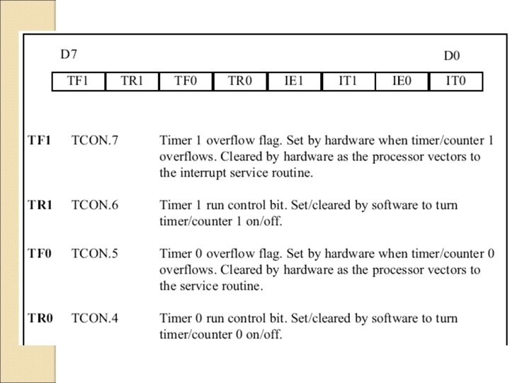
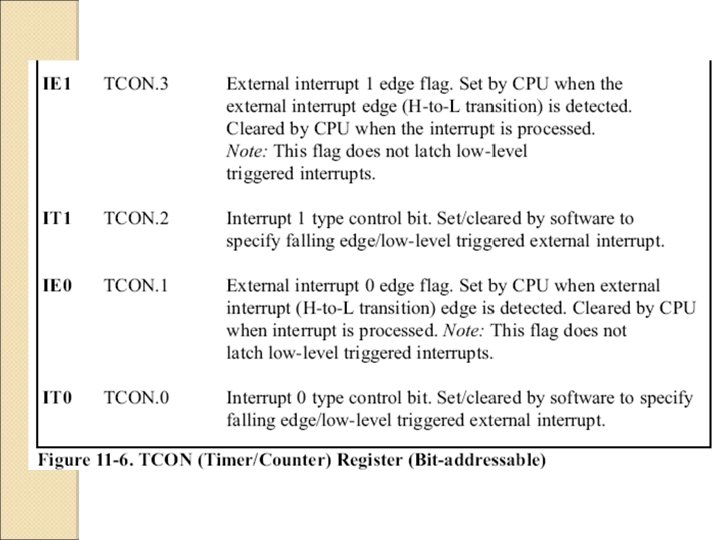
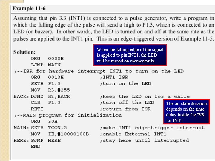
Edge-Triggered Interrupt To make INT 0 and INT 1 edgetriggered interrupts, we must program the bits of the TCON register ◦ The TCON register holds the IT 0 and IT 1 flag bits that determine level- or edgetriggered mode of the hardware interrupt IT 0 and IT 1 are bits D 0 and D 2 of TCON They are also referred to as TCON. 0 and TCON. 2 since the TCON register is bit-addressable
Sampling Edge-Triggered Interrupt The external source must be held high for at least one machine cycle, and then held low for at least one machine cycle ◦ The falling edge of pins INT 0 and INT 1 are latched by the 8051 and are held by the TCON. 1 and TCON. 3 bits of TCON register Function as interrupt-in-service flags It indicates that the interrupt is being serviced now On this INTn pin, no new interrupt will be responded to
Sampling Edge-Triggered Interrupt (cont. ) When the ISRs are finished, TCON. 1 and TCON. 3 are cleared ◦ The interrupt is finished and the 8051 is ready to respond to another interrupt on that pin During the time that the interrupt service routine is being executed, the INTn pin is ignored, no matter how many times it makes a high-to-low transition ◦ RETI clears the corresponding bit in TCON register (TCON. 1 or TCON. 3) There is no need for instruction CLR TCON. 1 before RETI in the ISR associated with INT 0
Serial Communication Interrupt TI (transfer interrupt) is raised when the stop bit is transferred ◦ Indicating that the SBUF register is ready to transfer the next byte RI (received interrupt) is raised when the stop bit is received ◦ Indicating that the received byte needs to be picked up before it is lost (overrun) by new incoming serial data
RI and TI Flags and Interrupts In the 8051 there is only one interrupt set aside for serial communication ◦ Used to both send and receive data ◦ If the interrupt bit in the IE register (IE. 4) is enabled, when RI or TI is raised the 8051 gets interrupted and jumps to memory location 0023 H to execute the ISR In that ISR we must examine the TI and RI flags to see which one caused the interrupt and respond accordingly
Use of Serial COM in 8051 The serial interrupt is used mainly for receiving data and is never used for sending data serially ◦ This is like getting a telephone call in which we need a ring to be notified ◦ If we need to make a phone call there are other ways to remind ourselves and there is no need for ringing ◦ However in receiving the phone call, we must respond immediately no matter what we are doing or we will miss the call
TRANS: RETI END
HERE: JNB CLR SJMP TRANS: RETI END TI, HERE TI BACK
Interrupt Flag Bits The TCON register holds four of the interrupt flags in the 8051 The SCON register has the RI and TI flags
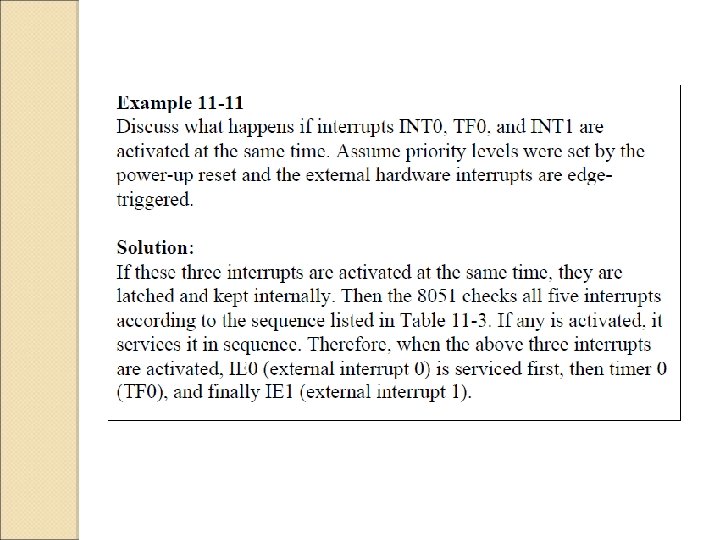
Interrupt Priority When the 8051 is powered up, the priorities are assigned ◦ In reality, the priority scheme is nothing but an internal polling sequence in which the 8051 polls the interrupts in the sequence listed and responds accordingly
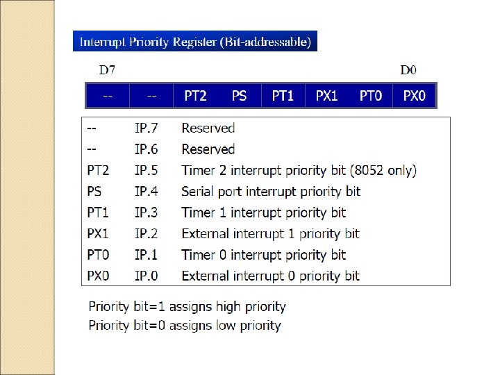
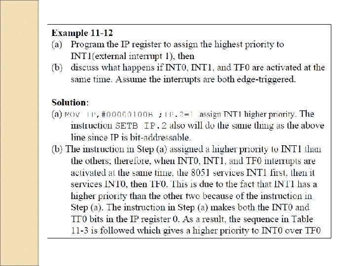
Altering Interrupt Priority We can alter the sequence of interrupt priority by programming a register called IP (interrupt priority) ◦ To give a higher priority to any of the interrupts, we make the corresponding bit in the IP register high ◦ When two or more interrupt bits in the IP register are set to high While these interrupts have a higher priority than others, they are serviced according to the sequence of Table 11 -13
External Interrupt 1 (INT 1)
Interrupt inside an Interrupt In the 8051 a low-priority interrupt can be interrupted by a higher-priority interrupt but not by another low priority interrupt ◦ Although all the interrupts are latched and kept internally, no low-priority interrupt can get the immediate attention of the CPU until the 8051 has finished servicing the high-priority interrupts
Triggering Interrupt by Software To test an ISR by way of simulation can be done with simple instructions to set the interrupts high ◦ Thereby cause the 8051 to jump to the interrupt vector table ◦ ex. If the IE bit for timer 1 is set, an instruction such as SETB TF 1 will interrupt the 8051 in whatever it is doing and will force it to jump to the interrupt vector table We do not need to wait for timer 1 go roll over to have an interrupt