Internet Routing Protocols DHCP and NAT Hwajung Lee


- Slides: 38

Internet Routing Protocols, DHCP, and NAT Hwajung Lee Modified from Slides Courtesy of Cisco Networking Academy and the book titled Communication Networks by Leon-Garcia

Contents • Basic Routing • Single Area Open Shortest Path First (OSPF) • Dynamic Host Configuration Protocol (DHCP) • Network Address Translation (NAT) § Summary

Autonomous Systems • Global Internet viewed as collection of autonomous systems. • Autonomous system (AS) is a set of routers or networks administered by a single organization • Same routing protocol need not be run within the AS • But, to the outside world, an AS should present a consistent picture of what ASs are reachable through it • Stub AS: has only a single connection to the outside world. • Multihomed AS: has multiple connections to the outside world, but refuses to carry transit traffic • Transit AS: has multiple connections to the outside world, and can carry transit and local traffic.

AS Number • For exterior routing, an AS needs a globally unique AS 16 -bit integer number • Stub AS, which is the most common type, does not need an AS number since the prefixes are placed at the provider’s routing table • Transit AS needs an AS number • Request an AS number from one of the five RIRs (Regional Internet Registries) • • • ARIN: American Registry for Internet Numbers RIPE NCC: Réseaux IP Européens Network Coordination Centre APNIC: Asia Pacific Network Information Centre LACNIC: Latin America and Caribbean Network Information Centre AFRINIC: African Network Information Centre

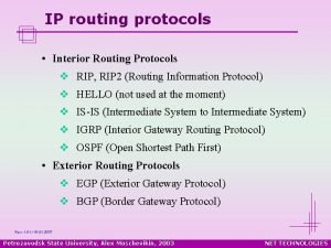
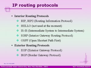
Inter and Intra Domain Routing Interior Gateway Protocol (IGP): routing within AS • RIP, OSPF, IGRP, EIGRP, IS-IS Exterior Gateway Protocol (EGP): routing between AS’s • BGPv 4 Border Gateways perform IGP & EGP routing IGP R EGP IGP R R R AS A AS C R R IGP AS B

Inter and Intra Domain Routing Image Source: www. netacad. com

Inter and Intra Domain Routing

Open Shortest Path First RFC 2328 (v 2) Fixes some of the deficiencies in RIP Enables each router to learn complete network topology Each router monitors the link state to each neighbor and floods the link-state information to other routers • Each router builds an identical link-state database • Allows router to build shortest path tree with router as root • OSPF typically converges faster than RIP when there is a failure in the network • •

OSPF Features • Multiple routes to a given destination, one per type of service • Support for variable-length subnetting by including the subnet mask in the routing message • Distribution of traffic over multiple paths of equal cost • Uses notion of area to partition sites into subsets • Support host-specific routes as well as net-specific routes • Designated router to minimize table maintenance overhead

Flooding • Used in OSPF to distribute link state (LS) information • Forward incoming packet to all ports except where packet came in • Packet eventually reaches destination as long as there is a path between the source and destination • Generates exponential number of packet transmissions • Approaches to limit # of transmissions: • Use a TTL at each packet; won’t flood if TTL is reached • Each router adds its identifier to header of packet before it floods the packet; won’t flood if its identifier is detected • Each packet from a given source is identified with a unique sequence number; won’t flood if sequence number is same

Example OSPF Topology 10. 5. 1. 1 10. 5. 1. 2 10. 5. 1. 3 10. 5. 1. 4 10. 5. 1. 6 10. 5. 1. 5 At steady state: l All routers have same LS database l Know how many routers in network l Interfaces & links between routers l Cost of each link l Occasional Hello messages (10 sec) & LS updates sent (30 min)

OSPF Network • To improve scalability, AS may be partitioned into areas • Area is identified by 32 -bit Area ID • Router in area only knows complete topology inside area & limits the flooding of link-state information to area • Area border routers summarize info from other areas • Each area must be connected to backbone area (0. 0) • Distributes routing info between areas • Internal router has all links to nets within the same area • Area border router has links to more than one area • Backbone router has links connected to the backbone

OSPF Areas To another AS N 1 R 1 N 2 R 2 N 5 R 3 R 6 N 4 R 7 N 6 R 4 R 5 N 3 Area 0. 0. 0. 1 ABR: 3, 6, 8 IR: 1, 2, 7 BR: 3, 4, 5, 6, 8 R 8 Area 0. 0. 0. 2 N 7 Area 0. 0. 0. 3 R = router N = network

Routing in the Distribution and Core Layers Configuring Single-Area OSPF

Routing in the Distribution and Core Layers Verifying Single-Area OSPF

Routing in the Distribution and Core Layers Verifying Single-Area OSPF (cont. )

Routing in the Distribution and Core Layers Verifying Single-Area OSPF (cont. )

DHCPv 4 Operation Introducing DHCPv 4 § DHCPv 4: § assigns IPv 4 addresses and other network configuration information dynamically § useful and timesaving tool for network administrators § dynamically assigns, or leases, an IPv 4 address from a pool of addresses § A Cisco router can be configured to provide DHCPv 4 services. § Administrators configure DHCPv 4 servers so that leases expire. Then the client must ask for another address, although the client is typically reassigned the same address.

DHCP Operation • Host broadcasts DHCP Discover message on its physical network • Server replies with Offer message (IP address + configuration information) • Host selects one offer and broadcasts DHCP Request message • Server allocates IP address for lease time T • Sends DHCP ACK message with T, and threshold times T 1 (=1/2 T) and T 2 (=. 875 T) • At T 1, host attempts to renew lease by sending DHCP Request message to original server • If no reply by T 2, host broadcasts DHCP Request to any server • If no reply by T, host must relinquish IP address and start from the beginning

DHCPv 4 Operation

DHCPv 4 Operation (cont. )

DHCPv 4 Operation DHCPv 4 Message Format

DHCPv 4 Operation DHCPv 4 Discover and Offer Messages

DHCPv 4 Operation DHCPv 4 Discover and Offer Messages (cont. )

Configure DHCPv 4 Server Configure a Basic DHCPv 4 Server A Cisco router running the Cisco IOS software can be configured to act as a DHCPv 4 server. To set up DHCP: 1. Exclude addresses from the pool. 2. Set up the DHCP pool name. 3. Define the range of addresses and subnet mask. Use the default-router command for the default gateway. Optional parameters that can be included in the pool – dns server, domain-name. To disable DHCP, use the no service dhcp command.

NAT Operation NAT Characteristics • IPv 4 Private Address Space • 10. 0 /8, 172. 16. 0. 0 /12, and 192. 168. 0. 0 /16 • What is NAT? • Process to translate network IPv 4 address • Conserve public IPv 4 addresses • Configured at the border router for translation • NAT Terminology • • • Inside address Inside local address Inside global address Outside local address Outside global address

NAT Operation Types of NAT • Static NAT • One-to-one mapping of local and global addresses • Configured by the network administrator and remain constant. • Dynamic NAT • Uses a pool of public addresses and assigns them on a first-come, first-served basis • Requires that enough public addresses for the total number of simultaneous user sessions • Port Address Translation (PAT) • Maps multiple private IPv 4 addresses to a single public IPv 4 address or a few addresses • Also known as NAT overload • Validates that the incoming packets were requested • Uses port numbers to forward the response packets to the correct internal device

NAT Operation NAT Advantages • Advantages of NAT • • Conserves the legally registered addressing scheme Increases the flexibility of connections to the public network Provides consistency for internal network addressing schemes Provides network security • Disadvantages of NAT • • • Performance is degraded End-to-end functionality is degraded End-to-end IP traceability is lost Tunneling is more complicated Initiating TCP connections can be disrupted

Configuring NAT Configuring Static NAT • Configuring Static NAT • Create the mapping between the inside local and outside local addresses • ip nat inside source static local-ip global-ip • Define which interfaces belong to the inside network and which belong to the outside network • ip nat inside • ip nat outside • Analyzing Static NAT • Verifying Static NAT show ip nat translations show ip nat statistics clear ip nat statistics

NAT – Sample Configuration access-list 1 permit 172. 16. 15. 0 0. 0. 0. 255 ip nat pool TEST 209. 165. 200. 225 209. 165. 200. 226 netmask 255. 252 ip nat inside source list 1 pool TEST overload [ip nat inside source list 1 s 0/1/0 overload] ip nat inside source static 172. 16. 15. 18 209. 165. 200. 227 interface s 0/0/0 ip nat inside interface s 0/0/1 ip nat inside interface s 0/1/0 ip nat outside

Configuring NAT Configuring Dynamic NAT • Dynamic NAT Operation • The pool of public IPv 4 addresses (inside global address pool) is available to any device on the inside network on a first-come, first-served basis. • With dynamic NAT, a single inside address is translated to a single outside address. • The pool must be large enough to accommodate all inside devices. • A device is unable to communicate to any external networks if no addresses are available in the pool.

Configuring NAT Configuring Dynamic NAT (Cont. ) • Configuring Dynamic NAT • Create the mapping between the inside local and outside local addresses • ip nat pool name start-ip end-ip {netmask | prefixlength prefix-length} • Create a standard ACL to permit those addresses to be translated • access-list-number permit source [source-wildcard] • Bind the ACL to the pool • ip nat inside source list access-list-number pool name • Identify the inside and outside interfaces • ip nat inside • ip nat outside

NAT – Sample Configuration access-list 1 permit 172. 16. 15. 0 0. 0. 0. 255 ip nat pool TEST 209. 165. 200. 225 209. 165. 200. 226 netmask 255. 252 ip nat inside source list 1 pool TEST ip nat inside source static 172. 16. 15. 18 209. 165. 200. 227 interface s 0/0/0 ip nat inside interface s 0/0/1 ip nat inside interface s 0/1/0 ip nat outside

Configuring NAT Configuring Port Address Translations (PAT) • Configuring PAT: Address Pool • Create the mapping between the inside local and outside local addresses • ip nat pool name start-ip end-ip {netmask | prefixlength prefix-length} • Create a standard ACL to permit those addresses to be translated • access-list-number permit source [source-wildcard] • Bind the ACL to the pool • ip nat inside source list access-list-number pool name overload • Identify the inside and outside interfaces • ip nat inside • ip nat outside

NAT – Sample Configuration access-list 1 permit 172. 16. 15. 0 0. 0. 0. 255 ip nat pool TEST 209. 165. 200. 225 209. 165. 200. 226 netmask 255. 252 ip nat inside source list 1 pool TEST overload [ip nat inside source list 1 s 0/1/0 overload] ip nat inside source static 172. 16. 15. 18 209. 165. 200. 227 interface s 0/0/0 ip nat inside interface s 0/0/1 ip nat inside interface s 0/1/0 ip nat outside

Configuring NAT Configuring Port Address Translations (PAT) (Cont. ) • Configuring PAT: Single Address • Define a standard ACL to permit those addresses to be translated • access-list-number permit source [source-wildcard] • Establish dynamic source translation, specify the ACL, exit interface, and overload option • ip nat inside source list access-list-number interface type name overload • Identify the inside and outside interfaces • ip nat inside • ip nat outside

NAT – Sample Configuration access-list 1 permit 172. 16. 15. 0 0. 0. 0. 255 ip nat pool TEST 209. 165. 200. 225 209. 165. 200. 226 netmask 255. 252 ip nat inside source list 1 pool TEST overload [ip nat inside source list 1 s 0/1/0 overload] ip nat inside source static 172. 16. 15. 18 209. 165. 200. 227 interface s 0/0/0 ip nat inside interface s 0/0/1 ip nat inside interface s 0/1/0 ip nat outside

Summary This chapter described: • Basic Routing • Open Shortest Path First (OSPF) • Dynamic Host Configuration Protocol (DHCP) • Network Address Translation (NAT)
 Bootp que es
 Dhcp and nat
 Dhcp and nat
 Lab 4-1: routing concepts and protocols
 Routing and switching protocols
 Igmpv
Igmpv Routing and switching protocols
 Dhcp routing protocol
 Ccna 2 chapter 3
 Write a detailed note on unicast routing protocols
 Stub link
 Routing protocols administrative distance
 Introduction to dynamic routing protocols
 Routing protocols
 Difference between reservoir routing and channel routing
 Mark tinka
 Hydrologic routing and hydraulic routing
 Comparison of clock routing and power routing
 Hwajung
 Hwajeong
 Hwajung
 Internet security protocols
 Irrpt
Irrpt Lab 3-5: install and configure dhcp and dns servers
 Difference between bootp and dhcp
 Proofs of work and bread pudding protocols
 Introduction to wan
 Cryptography standards and protocols
 Tcp and sctp are both layer protocols
 5 network topologies
 Snmp port number
 Lan standards and protocols
 Data link layer protocols for noisy and noiseless channels
 Plc norms
 Protocols and standards in computer networks
 Chapter 3 network protocols and communications
 Internet or internet
 Dhcp packet tracer
 Ettercap dhcp
