
Internal sensors Josep Amat and Alcia Casals Automatic
- Slides: 36
Internal sensors Josep Amat and Alícia Casals Automatic Control and Computer Engineering Department
Program Chapter 1. Introduction Chapter 2. Robot Morphology Chapter 3. Control Chapter 4. Robot programming Chapter 5. Perception Chapter 6. Mobile robots. Architecture, components and characteristics Chapter 7. Robotics applications. Robotization
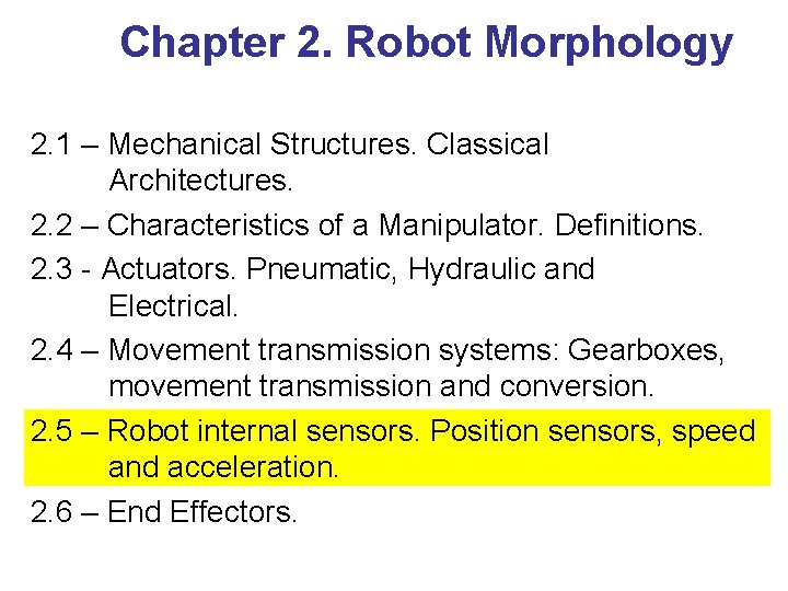
Chapter 2. Robot Morphology 2. 1 – Mechanical Structures. Classical Architectures. 2. 2 – Characteristics of a Manipulator. Definitions. 2. 3 - Actuators. Pneumatic, Hydraulic and Electrical. 2. 4 – Movement transmission systems: Gearboxes, movement transmission and conversion. 2. 5 – Robot internal sensors. Position sensors, speed and acceleration. 2. 6 – End Effectors.
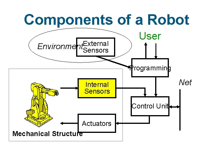
Components of a Robot Environment. External Sensors User Programming Net Internal Sensors Control Unit Actuators Mechanical Structure
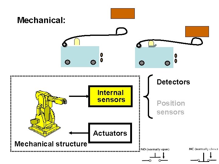
Mechanical: Detectors Internal sensors Actuators Mechanical structure Position sensors
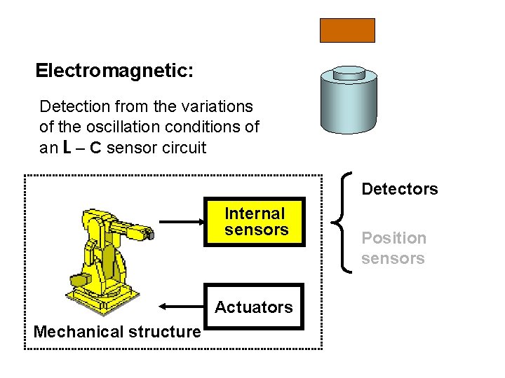
Electromagnetic: Detection from the variations of the oscillation conditions of an L – C sensor circuit Detectors Internal sensors Actuators Mechanical structure Position sensors
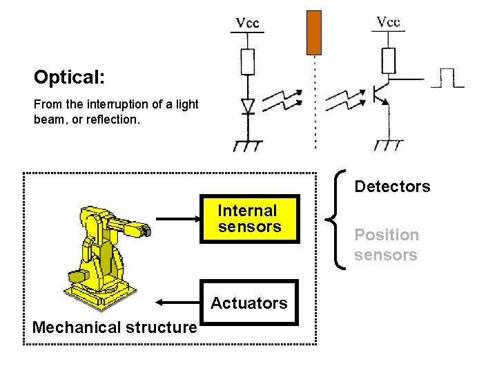
Optical: From the interruption of a light beam, or reflection. Detectors Internal sensors Actuators Mechanical structure Position sensors
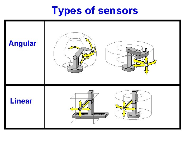
Types of sensors Angular Linear
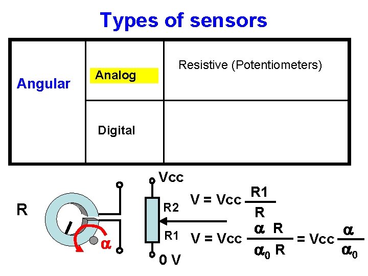
Types of sensors Angular Analog Resistive (Potentiometers) Digital Vcc R R 2 a R 1 0 V V = Vcc R 1 R a V = Vcc a 0 R
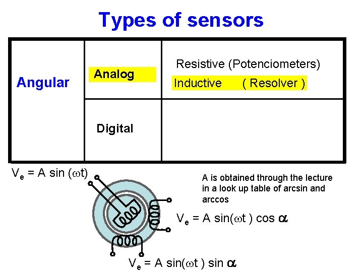
Types of sensors Angular Analog Resistive (Potenciometers) Inductive ( Resolver ) Digital Ve = A sin (wt) A is obtained through the lecture in a look up table of arcsin and arccos Ve = A sin(wt ) cos a Ve = A sin(wt ) sin a
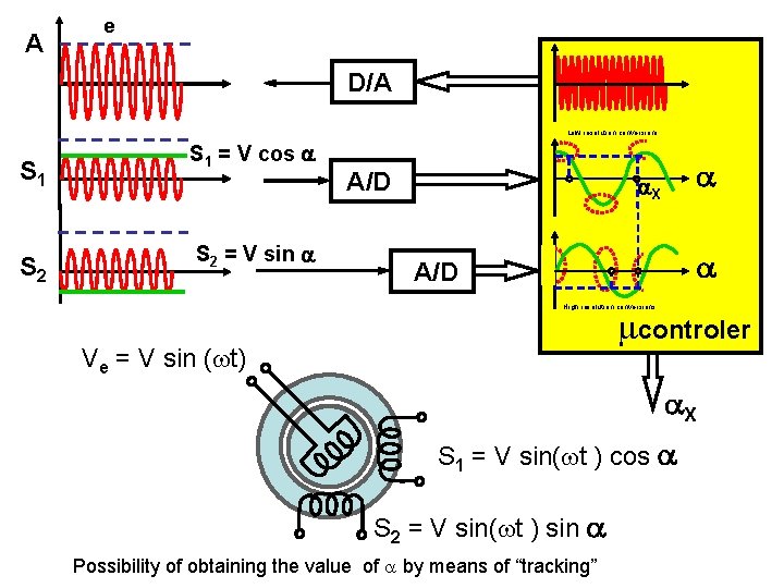
A e D/A Low resolution conversions S 1 S 2 S 1 = V cos a S 2 = V sin a A/D a a. X a A/D High resolution conversions mcontroler Ve = V sin (wt) a. X S 1 = V sin(wt ) cos a S 2 = V sin(wt ) sin a Possibility of obtaining the value of a by means of “tracking”
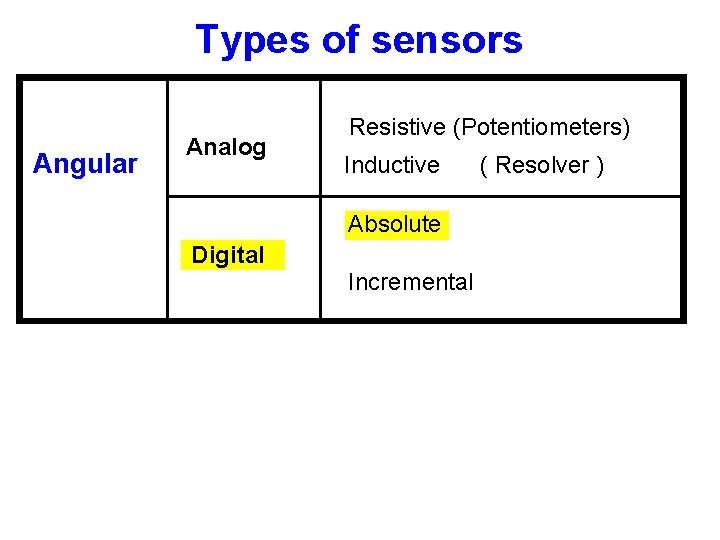
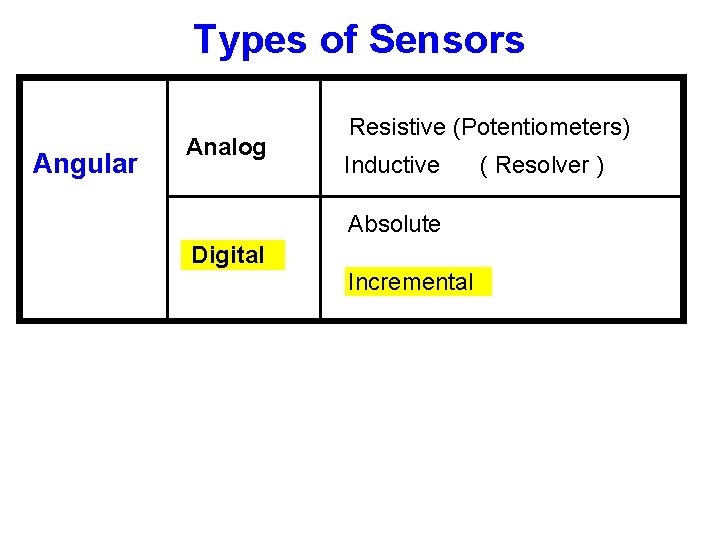
Types of sensors Angular Analog Resistive (Potentiometers) Inductive Absolute Digital Incremental ( Resolver )
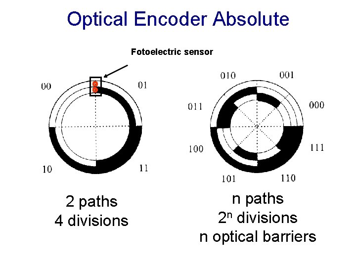
Optical Encoder Absolute Fotoelectric sensor 2 paths 4 divisions n paths 2 n divisions n optical barriers
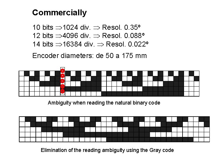
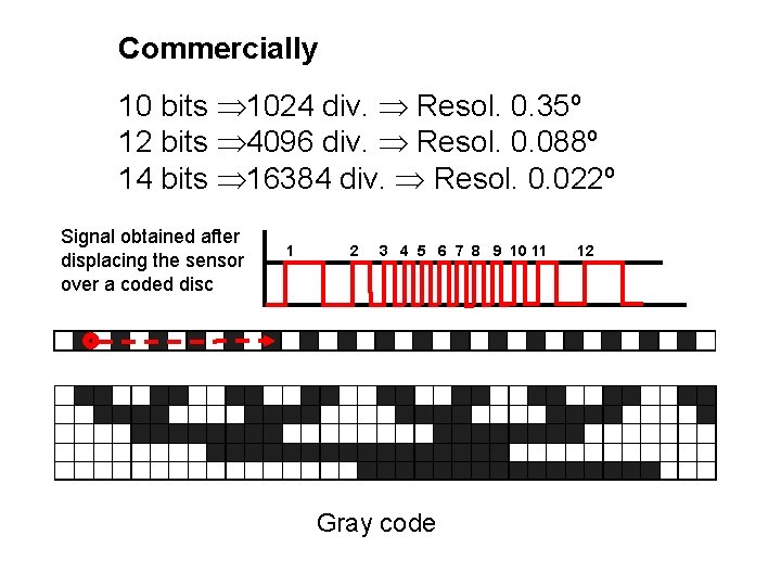
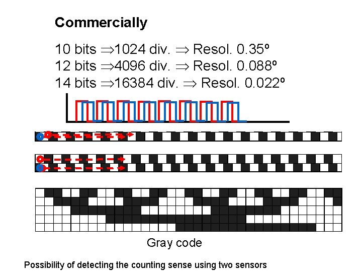
Commercially 10 bits 1024 div. Resol. 0. 35º 12 bits 4096 div. Resol. 0. 088º 14 bits 16384 div. Resol. 0. 022º Encoder diameters: de 50 a 175 mm Ambiguity when reading the natural binary code Elimination of the reading ambiguity using the Gray code
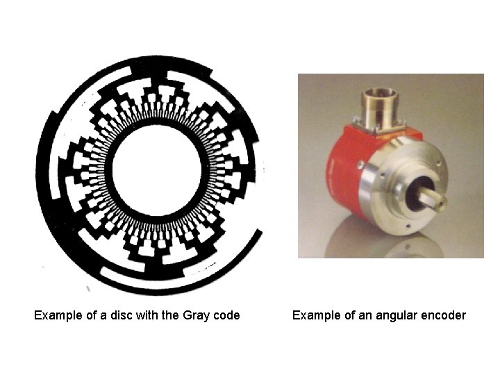
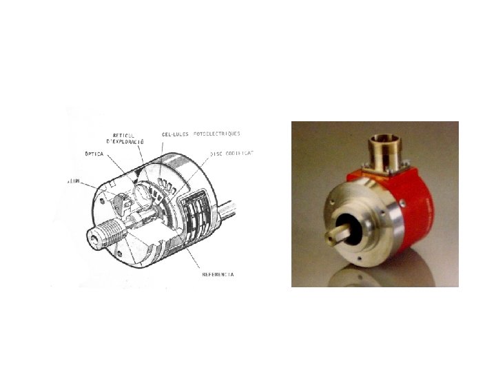
Example of a disc with the Gray code Example of an angular encoder
Types of Sensors Angular Analog Resistive (Potentiometers) Inductive Absolute Digital Incremental ( Resolver )
Commercially 10 bits 1024 div. Resol. 0. 35º 12 bits 4096 div. Resol. 0. 088º 14 bits 16384 div. Resol. 0. 022º Signal obtained after displacing the sensor over a coded disc 1 2 3 4 5 6 7 8 9 10 11 Gray code 12
Commercially 10 bits 1024 div. Resol. 0. 35º 12 bits 4096 div. Resol. 0. 088º 14 bits 16384 div. Resol. 0. 022º Gray code Possibility of detecting the counting sense using two sensors
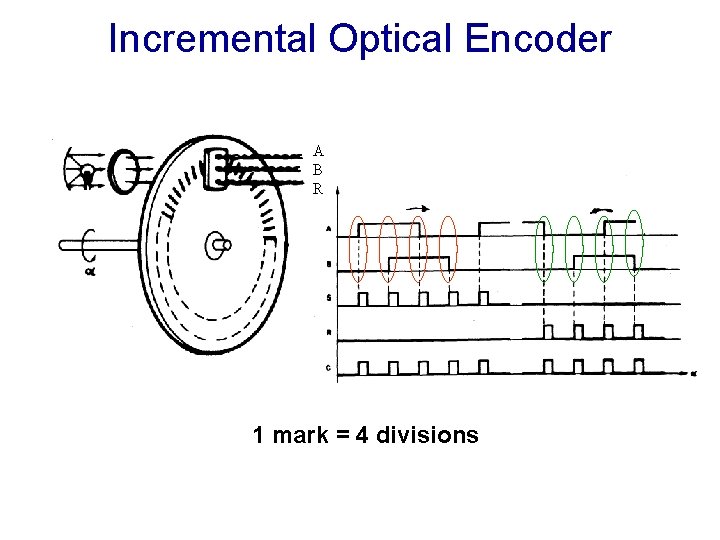
Incremental Optical Encoder A B R 1 mark = 4 divisions
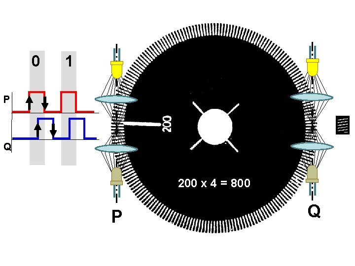
0 1 P Q 200 x 4 = 800 P Q
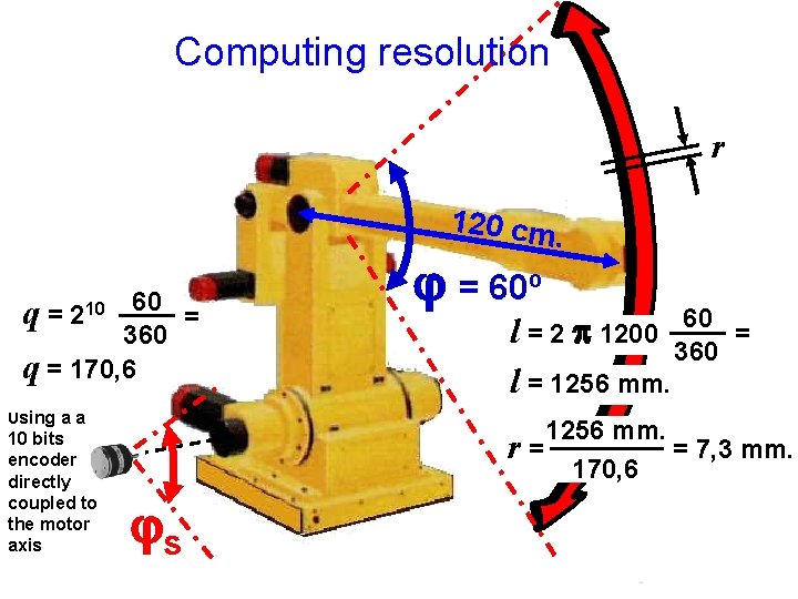
Computing resolution r 120 cm. q = 210 60 = 360 q = 170, 6 Using a a 10 bits encoder directly coupled to the motor axis j = 60º 60 l = 2 p 1200 = 360 l = 1256 mm. r= = 7, 3 mm. 170, 6 js
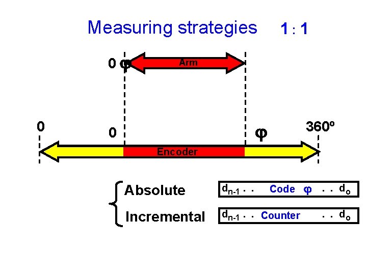
Measuring strategies 0 j 0 1: 1 Arm 360º j 0 Encoder Absolute dn-1. . Incremental dn-1. . Counter Code j. . do
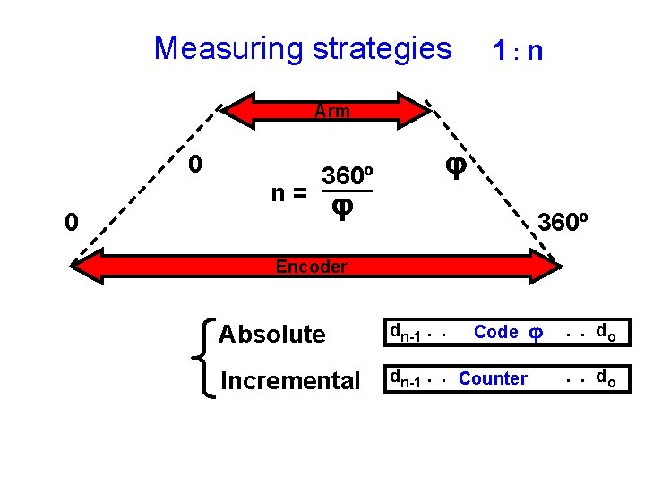
Measuring strategies 1: n Arm 0 n= 360º 0 j j 360º Encoder Absolute dn-1. . Incremental dn-1. . Counter Code j . . do
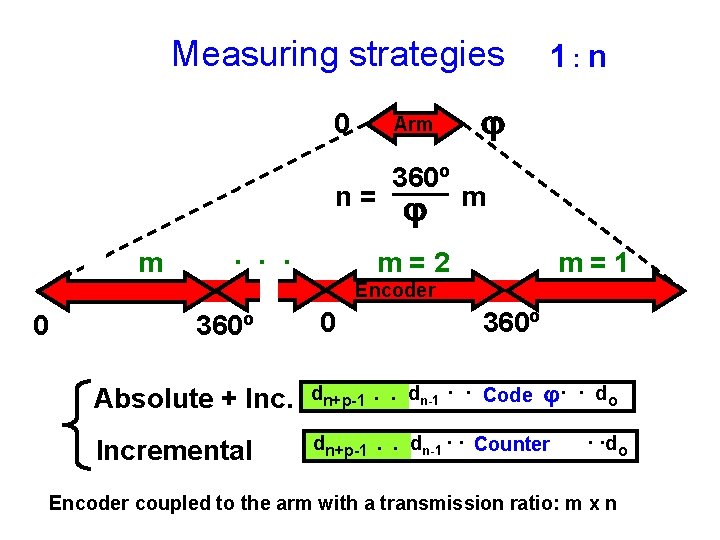
Measuring strategies 0 Arm n= m · · · 360º j 1: n j m m=2 m=1 Encoder 0 360º j · · do Absolute + Inc. dn+p-1. . dn-1 · · Code Incremental dn+p-1. . dn-1 · · Counter · ·do Encoder coupled to the arm with a transmission ratio: m x n
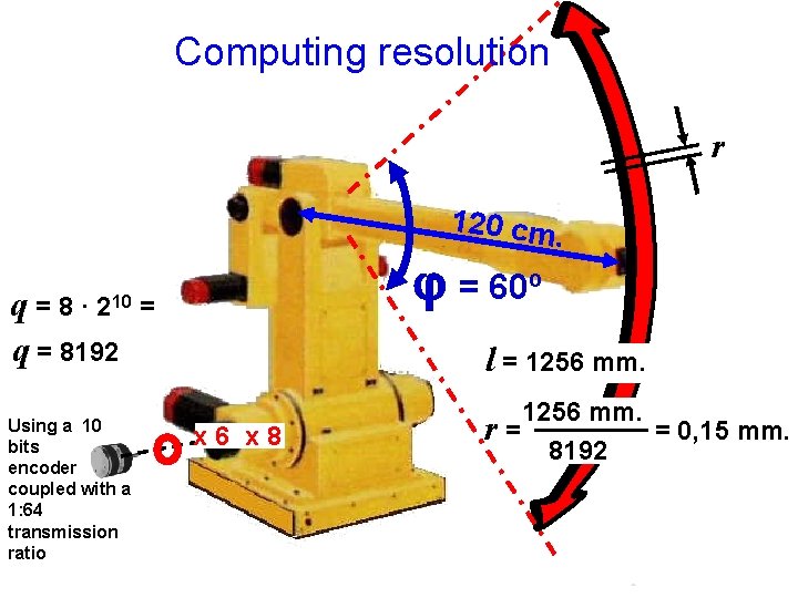
Computing resolution r 120 cm. q=8· q = 8192 210 Using a 10 bits encoder coupled with a 1: 64 transmission ratio j = 60º = l = 1256 mm. x 6 x 8 1256 mm. = 0, 15 mm. r= 8192
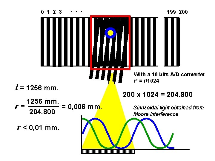
0 1 2 3 · · · l = 1256 mm. r= = 0, 006 mm. 204. 800 r < 0, 01 mm. 199 200 With a 10 bits A/D converter r’ = r/1024 200 x 1024 = 204. 800 Sinusoidal light obtained from Moore interference
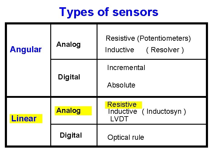
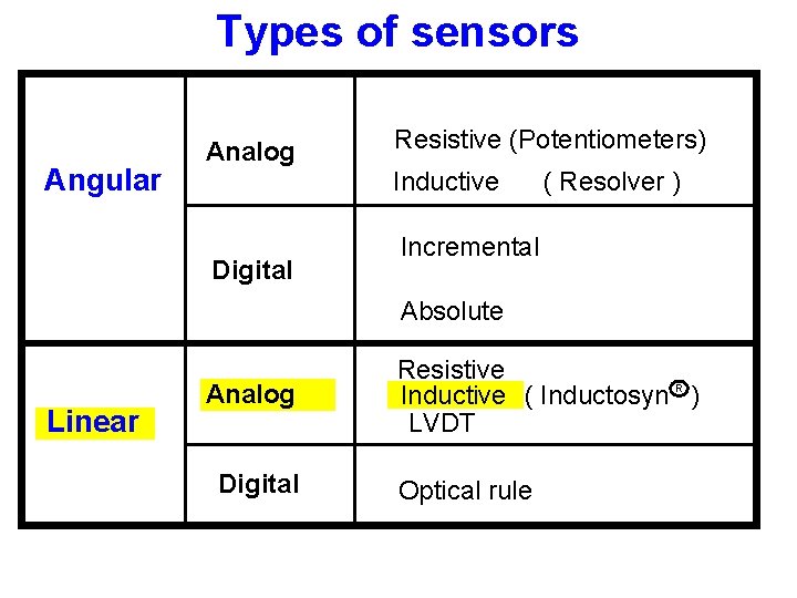
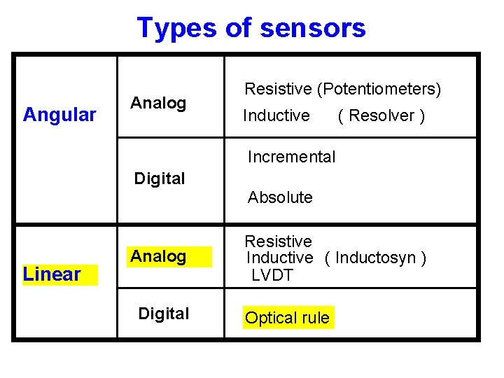
Types of sensors Angular Analog Resistive (Potentiometers) Inductive ( Resolver ) Incremental Digital Absolute Linear Analog Digital Resistive Inductive ( Inductosyn ) LVDT Optical rule
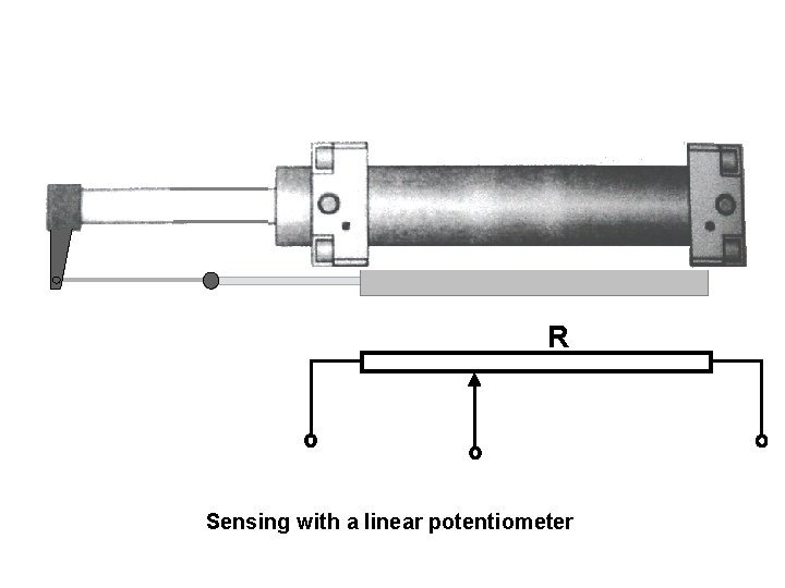
R Sensing with a linear potentiometer
Types of sensors Angular Analog Resistive (Potentiometers) Inductive Digital ( Resolver ) Incremental Absolute Linear Analog Digital Resistive Inductive ( Inductosyn R ) LVDT Optical rule
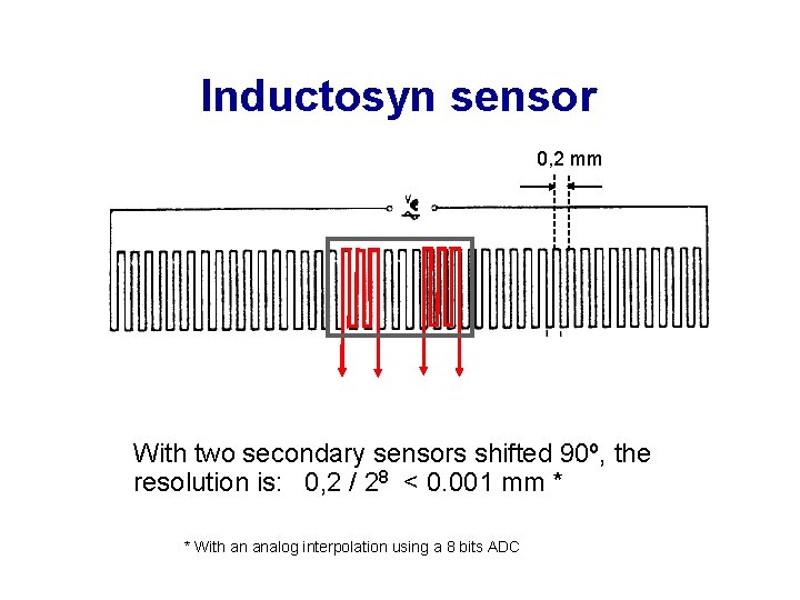
Inductosyn sensor 0, 2 mm With two secondary sensors shifted 90º, the resolution is: 0, 2 / 28 < 0. 001 mm * * With an analog interpolation using a 8 bits ADC
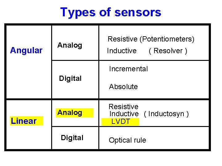
Types of sensors Angular Analog Resistive (Potentiometers) Inductive ( Resolver ) Incremental Digital Absolute Linear Analog Digital Resistive Inductive ( Inductosyn ) LVDT Optical rule
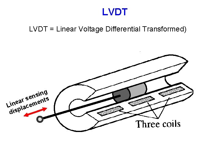
LVDT = Linear Voltage Differential Transformed) ing s n se nts r a e e Lin lacem disp
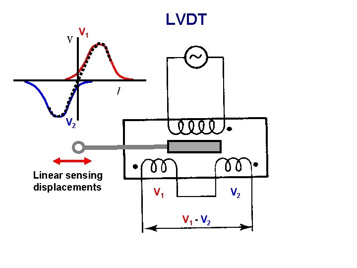
v LVDT V 1 V 2 Linear sensing displacements V 1 V 2 V 1 - V 2
Types of sensors Angular Analog Resistive (Potentiometers) Inductive ( Resolver ) Incremental Digital Absolute Linear Analog Digital Resistive Inductive ( Inductosyn ) LVDT Optical rule
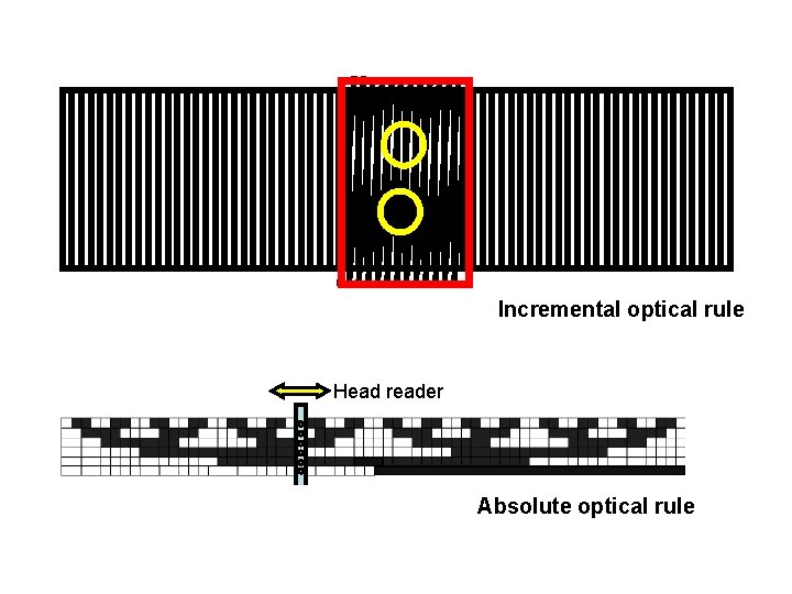
Incremental optical rule Head reader Absolute optical rule