Intermolecular Forces between rather than within molecules dipoledipole
 molecules. Ô dipole-dipole attraction: molecules with dipoles orient")
Intermolecular Forces between (rather than within) molecules. Ô dipole-dipole attraction: molecules with dipoles orient themselves so that “+” and “ ” ends of the dipoles are close to each other. Ô hydrogen bonds: dipole-dipole attraction in which hydrogen is bound to a highly electronegative atom. (F, O, N) Copyright© 2000 by Houghton Mifflin Company. All rights reserved. 1
 The electrostatic interaction of two polar molecules. (b) The interaction")
Figure 10. 2: (a) The electrostatic interaction of two polar molecules. (b) The interaction of many dipoles in a condensed state.
 The polar water molecule. (b) Hydrogen bonding among water molecules.")
Figure 10. 3: (a) The polar water molecule. (b) Hydrogen bonding among water molecules. Copyright© 2000 by Houghton Mifflin Company. All rights reserved. 3

Figure 10. 4: The boiling points of the covalent hydrides of the elements in Groups 4 A, 5 A, 6 A, and 7 A. General trend to increase down the group Small size Large electronegativity Copyright© 2000 by Houghton Mifflin Company. All rights reserved. 4

London Dispersion Forces 4 relatively weak forces that exist among noble gas atoms and nonpolar molecules. (Ar, C 8 H 18) 4 caused by instantaneous dipole, in which electron distribution becomes asymmetrical. 4 the ease with which electron “cloud” of an atom can be distorted is called polarizability. Copyright© 2000 by Houghton Mifflin Company. All rights reserved. 5
 An instantaneous polarization can occur on atom A, creating an")
Figure 10. 5: (a) An instantaneous polarization can occur on atom A, creating an instantaneous dipole. This dipole creates an induced dipole on neighboring atom B. (b) Nonpolar molecules such as H 2 also can develop instantaneous and induced dipoles.

Copyright© 2000 by Houghton Mifflin Company. All rights reserved. 7

Some Properties of a Liquid Surface Tension: The resistance to an increase in its surface area (polar molecules). Capillary Action: Spontaneous rising of a liquid in a narrow tube. Adhesion- stick to walls Cohesion- stick to each other Viscosity: Resistance to flow (molecules with large intermolecular forces). Copyright© 2000 by Houghton Mifflin Company. All rights reserved. 8

Figure 10. 6: A molecule in the interior of a liquid is attracted by the molecules surrounding it, whereas a molecule at the surface of a liquid is attracted only by molecules below it and on each side. Copyright© 2000 by Houghton Mifflin Company. All rights reserved. 9

Figure 10. 7: Nonpolar liquid mercury forms a convex meniscus in a glass tube, whereas polar water forms a concave meniscus. Which has stronger cohesive forces? Copyright© 2000 by Houghton Mifflin Company. All rights reserved. water 10
, amethyst (right). Copyright© 2000 by Houghton")
Figure 10. 8: Two crystalline solids: pyrite (left), amethyst (right). Copyright© 2000 by Houghton Mifflin Company. All rights reserved. 11

Types of Solids Crystalline Solids: highly regular arrangement of their components [table salt (Na. Cl), pyrite (Fe. S 2)]. Amorphous solids: considerable disorder in their structures (glass). Copyright© 2000 by Houghton Mifflin Company. All rights reserved. 12

Representation of Components in a Crystalline Solid Lattice: A 3 -dimensional system of points designating the centers of components (atoms, ions, or molecules) that make up the substance. Copyright© 2000 by Houghton Mifflin Company. All rights reserved. 13

Crystal lattice of alternating positive and negative ions. Ti. O 2 Na. Cl Cs. Cl

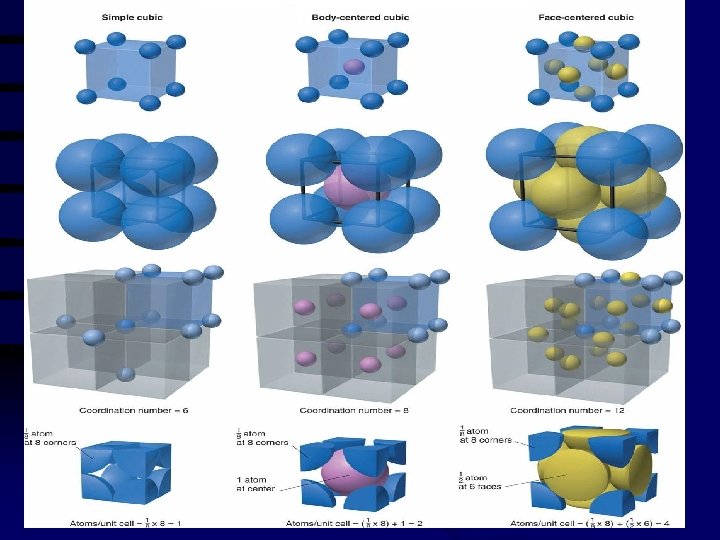
Coordination number of an ion is the number of ions of opposite charge That surround the ion in a crystal Sodium Chloride: Each Na+ is surrounded by 6 Cl- , therefore the Coordination # = 6 Each Cl- is surrounded by 6 Na+ Cubic centered

Metallic Crystals q Metals are made up of closely packed cations rather than neutral atoms. q Chemical bonding results from the attraction between metal ions and the surrounding sea of electrons. q Vacant p and d orbitals in metal's outer energy levels overlap, and allow outer electrons to move about the metal.

Because of this arrangement q Metals are good conductors of heat and electricity q Metals are malleable q Metals are ductile q Metals have high tensile strength q Metals have luster

Packing in Metals Model: Packing uniform, hard spheres to best use available space. This is called closest packing. Each atom has 12 nearest neighbors.

Every atom has 8 neighbors Every atom has 12 neighbors

Metal Alloys v. Substitutional Alloy: some metal atoms replaced by others of similar size.
 in closest packed metal structure are occupied")
Metal Alloys v. Interstitial Alloy: Interstices (holes) in closest packed metal structure are occupied by small atoms.

Figure 10. 9: Three cubic unit cells and the corresponding lattices.
 An atomic solid.")
Figure 10. 12: Examples of three types of crystalline solids. (a) An atomic solid. (b) An ionic solid. (c) A molecular solid. Copyright© 2000 by Houghton Mifflin Company. All rights reserved. 24

Representation of Components in a Crystalline Solid Unit Cell: The smallest repeating unit of the lattice. 4 4 4 simple cubic body-centered cubic face-centered cubic Copyright© 2000 by Houghton Mifflin Company. All rights reserved. 25

Types of Crystalline Solids Ionic Solid: contains ions at the points of the lattice that describe the structure of the solid (Na. Cl). Molecular Solid: discrete covalently bonded molecules at each of its lattice points (sucrose, ice). Atomic Solid: have atoms at the lattice points. metallic, network, and group 8 A solids Copyright© 2000 by Houghton Mifflin Company. All rights reserved. 26

Copyright© 2000 by Houghton Mifflin Company. All rights reserved. 27
 aba packing (b)")
Figure 10. 13: The closest packing arrangement of uniform spheres, (a) aba packing (b) abc packing. Copyright© 2000 by Houghton Mifflin Company. All rights reserved. 28

packed so that the spheres in the third layer are directly over those in the first layer (aba), the unit cell is the hexagonal prism illustrated here in red. Copyright© 2000 by Houghton Mifflin Company. All rights reserved. 29

Figure 10. 15: When spheres are packed in the abc arrangement, the unit cell is face-centered cubic. Copyright© 2000 by Houghton Mifflin Company. All rights reserved. 30

Figure 10. 16: The indicated sphere has 12 nearest neighbors.

Figure 10. 17: The net number of spheres in a face-centered cubic unit cell. Copyright© 2000 by Houghton Mifflin Company. All rights reserved. 32

Crystalline silver contains cubic closest packed silver atoms. Copyright© 2000 by Houghton Mifflin Company. All rights reserved. 33
 Representation of an alkali metal (Group 1 A) with one valence electron. (b)")
(a) Representation of an alkali metal (Group 1 A) with one valence electron. (b) Representation of an alkaline earth metal (Group 2 A) with two valence electrons. Copyright© 2000 by Houghton Mifflin Company. All rights reserved. 34

Packing in Metals Model: Packing uniform, hard spheres to best use available space. This is called closest packing. Each atom has 12 nearest neighbors. 4 hexagonal closest packed (“aba”) 4 cubic closest packed (“abc”) Copyright© 2000 by Houghton Mifflin Company. All rights reserved. 35

Bonding Models for Metals Electron Sea Model: A regular array of metals in a “sea” of electrons. Band (Molecular Orbital) Model: Electrons assumed to travel around metal crystal in MOs formed from valence atomic orbitals of metal atoms. Copyright© 2000 by Houghton Mifflin Company. All rights reserved. 36
 A representation of the energy levels (bands) in a magnesium")
Figure 10. 20: (left) A representation of the energy levels (bands) in a magnesium crystal. (right) Crystals of magnesium grown from a vapor. Copyright© 2000 by Houghton Mifflin Company. All rights reserved. 37

Figure 10. 21: Two types of alloys.

Metal Alloys Substances that have a mixture of elements and metallic properties. 1. Substitutional Alloy: some metal atoms replaced by others of similar size. brass = Cu/Zn (1/3 of Cu replaced by Zn) sterling silver= Ag/Cu pewter=Sn/Cu. Bi. At Copyright© 2000 by Houghton Mifflin Company. All rights reserved. 39
 2. Interstitial Alloy: Interstices (holes) in closest packed metal structure are")
Metal Alloys (continued) 2. Interstitial Alloy: Interstices (holes) in closest packed metal structure are occupied by small atoms. steel = iron + carbon (change from indirectional to directional bonds) 3. Both types: Alloy steels contain a mix of substitutional (carbon) and interstitial (Cr, Mo) alloys. Copyright© 2000 by Houghton Mifflin Company. All rights reserved. 40

Network Solids Composed of strong directional covalent bonds that are best viewed as a “giant molecule”. 4 4 4 brittle do not conduct heat or electricity carbon, silicon-based graphite, diamond, ceramics, glass Copyright© 2000 by Houghton Mifflin Company. All rights reserved. 41
 tetrahedral arrangement hard, colorless, an insulator • Graphite (sp")
• Diamond (sp 3) tetrahedral arrangement hard, colorless, an insulator • Graphite (sp 2) layers of six member rings slippery, black, conductor (delocalization of the π bonds) Copyright© 2000 by Houghton Mifflin Company. All rights reserved. 42

Figure 10. 22: The structures of diamond and graphite. In each case only a small part of the entire structure is shown.
 diamond and")
Figure 10. 23: Partial representation of the molecular orbital energies in (a) diamond and (b) a typical metal. Copyright© 2000 by Houghton Mifflin Company. All rights reserved. 44
 perpendicular to the plane of the carbon")
Figure 10. 24: The p orbitals (a) perpendicular to the plane of the carbon ring system in graphite can combine to form (b) an extensive π-bonding network. Copyright© 2000 by Houghton Mifflin Company. All rights reserved. 45

Figure 10. 25: Graphite consists of layers of carbon atoms. Copyright© 2000 by Houghton Mifflin Company. All rights reserved. 46
 • Silicates- found in rocks,")
Silicon • Silicon-oxygen compound Si. O 4 silica (tetrahedral) • Silicates- found in rocks, soil, and clay. • Silica is heated and cooled rapidly- glass Copyright© 2000 by Houghton Mifflin Company. All rights reserved. 47

Computer-generated model of silica. Copyright© 2000 by Houghton Mifflin Company. All rights reserved. 48
 The structure of quartz (empirical formula Si. O 2). Quartz")
Figure 10. 26: (top) The structure of quartz (empirical formula Si. O 2). Quartz contains chains of Si. O 4 tetrahedra (bottom) that share oxygen atoms.

Figure 10. 27: Examples of silicate anions, all of which are based on Si. O 44 tetrahedra. Copyright© 2000 by Houghton Mifflin Company. All rights reserved. 50
 a quartz crystal and (b) a quartz")
Figure 10. 28: Twodimensional representations of (a) a quartz crystal and (b) a quartz glass.
 and firing at high temp. non")
ceramics • From clay (contain silicates, like glass) and firing at high temp. non metallic, strong, brittle, and resistant to heat and chemicals Glass- homogeneous Ceramics- heterogeneous ( crystal of silicates suspended in a glassy cement) Copyright© 2000 by Houghton Mifflin Company. All rights reserved. 52

Semiconductors A substance in which some electrons can cross the band gap. Conductivity increases w/increase in temp. 4 Conductivity is enhanced by doping with group 3 a or group 5 a elements. 4 N-type (As; has 1 more e-) 4 P-type (B; has 1 less e-) Copyright© 2000 by Houghton Mifflin Company. All rights reserved. 53
 A silicon crystal doped with arsenic, which has one more valence electron than")
(a) A silicon crystal doped with arsenic, which has one more valence electron than silicon. (b) A silicon crystal doped with boron, which has one less electron than silicon.
 an n-type semiconductor and (b) a ptype")
Figure 10. 30: Energy-level diagrams for (a) an n-type semiconductor and (b) a ptype semiconductor. Copyright© 2000 by Houghton Mifflin Company. All rights reserved. 55

Figure 10. 31: The p-n junction involves the contact of a p-type and an n-type semiconductor.

Figure 10. 32: A schematic of two circuits connected by a transistor. The signal in circuit 1 is amplified in circuit 2. Copyright© 2000 by Houghton Mifflin Company. All rights reserved. 57

Figure 10. 33: The steps forming a transistor in a crystal of initially pure silicon.

Molecular Solids • • Ice- lattice is occupied by H 2 O molecules Dry ice- solid CO 2 Sulfur- contain S 8 Phosphorus- P 4 (white phosphorus) • CO 2, I 2, S 8, P 4 (London dispersion) (gas) Copyright© 2000 by Houghton Mifflin Company. All rights reserved. 59

A “steaming” piece of dry ice. Copyright© 2000 by Houghton Mifflin Company. All rights reserved. 60
 contain S 8 molecules. (b) White phosphorus (containing P 4 molecules) is so")
(yellow) contain S 8 molecules. (b) White phosphorus (containing P 4 molecules) is so reactive with the oxygen in air that it must be stored under water.

Copyright© 2000 by Houghton Mifflin Company. All rights reserved. 62

Ionic Solids • Stable, high melting point substances, held together by strong electrostatic forces between oppositely charged ions. • Closest packing model, where the smaller cation fits in the holes. Copyright© 2000 by Houghton Mifflin Company. All rights reserved. 63
 The")
Figure 10. 35: The holes that exist among closest packed uniform spheres. (a) The trigonal hole formed by three spheres in a given plane. (b) The tetrahedral hole formed when a sphere occupies a dimple formed by three spheres in an adjacent layer. (c) The octahedral hole formed by six spheres in two adjacent layers.

• Trigonal hole never reached by ionic solids. Copyright© 2000 by Houghton Mifflin Company. All rights reserved. 65
 The location (X) of a tetrahedral hole in the face-centered")
Figure 10. 36: (a) The location (X) of a tetrahedral hole in the face-centered cubic unit cell. (b) One of the tetrahedral holes. (c) The unit cell for Zn. S where the S 2 - ions (yellow) are closest packed with the Zn 2+ ions (red) in alternating tetrahedral holes. Copyright© 2000 by Houghton Mifflin Company. All rights reserved. 66
 The locations (gray X) of the octahedral holes in the")
Figure 10. 37: (a) The locations (gray X) of the octahedral holes in the face-centered cubic unit cell. (b) Representation of the unit cell for solid Na. Cl.

Copyright© 2000 by Houghton Mifflin Company. All rights reserved. 68

Vapor Pressure a nd Changes of State • Molecules of a liquid escape the liquid’s surface and form a gas- Vaporization or Evaporation. Endothermic (overcome intermolecular forces) Copyright© 2000 by Houghton Mifflin Company. All rights reserved. 69
 Energy required to vaporize 1")
Heat of vaporization, or enthalpy of vaporization (ΔHvap ) Energy required to vaporize 1 mol of liquid at 1 atm. H 2 O has a large heat of vaporization(40. 7 k. J) Copyright© 2000 by Houghton Mifflin Company. All rights reserved. 70

Figure 10. 38: Behavior of a liquid in a closed container. Initial transfer of liquid to the vapor phase. Initially the # of vapor molecules increase and so does the rate of return. (condensation). Eventually equilibrium occurs Copyright© 2000 by Houghton Mifflin Company. All rights reserved. 71

Figure 10. 39: The rates of condensation and evaporation over time for a liquid sealed in a closed container. Copyright© 2000 by Houghton Mifflin Company. All rights reserved. 72

Vapor Pressure. . . is the pressure of the vapor present at equilibrium. . is determined principally by the size of the intermolecular forces in the liquid. . increases significantly with temperature. Volatile liquids have high vapor pressures. Copyright© 2000 by Houghton Mifflin Company. All rights reserved. 73
 The vapor pressure of a liquid can be measured easily")
Figure 10. 40: (a) The vapor pressure of a liquid can be measured easily using a simple barometer of the type shown here. (b) The three liquids, water, ethanol (C 2 H 5 OH), and diethyl ether [(C 2 H 5)2 O], have quite different vapor pressures. Copyright© 2000 by Houghton Mifflin Company. All rights reserved. 74

• In general substances with large molar masses have low vapor pressures (Large dispersion forces) ( the more e- the more polarizable) • H 2 O smaller molar mass but has H-bonding (stronger!!!) Copyright© 2000 by Houghton Mifflin Company. All rights reserved. 75

Figure 10. 41: Diagram showing the reason vapor pressure depends on temperature. Vapor Pressure increases w/increased Temp. Copyright© 2000 by Houghton Mifflin Company. All rights reserved. 76
 The vapor pressure of water, ethanol, and diethyl ether as")
Figure 10. 42: (a) The vapor pressure of water, ethanol, and diethyl ether as a function of temperature. (b) Plots of In(Pvap) versus 1/T (Kelvin temperature) for water, ethanol, and diethyl ether. Copyright© 2000 by Houghton Mifflin Company. All rights reserved. 77

Copyright© 2000 by Houghton Mifflin Company. All rights reserved. 78

Figure 10. 43: Iodine being heated, causing it to sublime onto an evaporating dish cooled by ice. From solid to a gas Copyright© 2000 by Houghton Mifflin Company. All rights reserved. 79
 for a given quantity")
Figure 10. 44: The heating curve (not drawn to scale) for a given quantity of water where energy is added at a constant rate. Copyright© 2000 by Houghton Mifflin Company. All rights reserved. 80

Melting Point Vibration of water molecules increases as T increases. Molecules break loose from lattice points and solid changes to liquid. (Temperature is constant as melting occurs. ) vapor pressure of solid = vapor pressure of liquid Plateau at 0°C. Copyright© 2000 by Houghton Mifflin Company. All rights reserved. 81

Heat of fusion, enthalpy of fusion ΔHfus • Enthalpy change that occurs at MP Copyright© 2000 by Houghton Mifflin Company. All rights reserved. 82

Copyright© 2000 by Houghton Mifflin Company. All rights reserved. 83

Boiling Point At 100°C the liquid water reaches BP. Constant temperature when added energy is used to vaporize the liquid. vapor pressure of liquid = pressure of surrounding atmosphere ***All intermolecular changes (physical) no intermolecular bonds broken. Copyright© 2000 by Houghton Mifflin Company. All rights reserved. 84

Figure 10. 46: Solid and liquid phases in equilibrium with the vapor pressure.

• Normal melting point- T at which the solid and liquid states have the same vapor pressure under conditions were the total pressure is 1 atm. • Normal boiling point- T at which the vapor pressure of the liquid is exactly 1 atm Copyright© 2000 by Houghton Mifflin Company. All rights reserved. 86

Figure 10. 47: Water in a closed system with a pressure of 1 atm exerted on the piston. No bubbles can form within the liquid as long as the vapor pressure is less than 1 atm.

Super cooling • Cooled below O°C at 1 atm and remain in the liquid state. • As it is cooled it may not reach the degree of organization necessary to form ice at O°C. Copyright© 2000 by Houghton Mifflin Company. All rights reserved. 88

Figure 10. 48: The supercooling of water. The extent of supercooling is given by S.

Boiling chip releasing air bubbles acts as a nucleating agent for the bubbles that form when water boils. Copyright© 2000 by Houghton Mifflin Company. All rights reserved. 90

Figure 10. 49: The phase diagram for water. Copyright© 2000 by Houghton Mifflin Company. All rights reserved. 91

Figure 10. 47: Water in a closed system with a pressure of 1 atm exerted on the piston. No bubbles can form within the liquid as long as the vapor pressure is less than 1 atm.
 T=-20°C Piston= 1")
Pressure at 1 atm • • Filled w/ice (no air space) T=-20°C Piston= 1 atm pressure Since T<0, VP of ice is <1 atm, no vapor present As heated ice is only component until T=0 VP(solid)=VP(liquid) melting Still no vapor ; P <1 atm Copyright© 2000 by Houghton Mifflin Company. All rights reserved. 93

• Solid completely to liquid, temp changes • Now only water (still no vapor) • T=100 C ; VP= 1 atm; boiling occurs; change to vapor • Liquid completely to vapor, temp rises. Copyright© 2000 by Houghton Mifflin Company. All rights reserved. 94

Figure 10. 50: Diagrams of various heating experiments on samples of water in a closed system.

Experiment 2 • • • P=2 torr T= -20 Just ice T increases to -10 , sublimation occurs VP of ice = external pressure No liquid because the VP of liquid is always greater than 2 torr Copyright© 2000 by Houghton Mifflin Company. All rights reserved. 96

Experiment 3 • Pressure 4. 58 torr • T= -20, only ice • New phase when T=0. 01°C; Triple Point solid and liquid water have identical VP of 4. 58. All three phases exist. Copyright© 2000 by Houghton Mifflin Company. All rights reserved. 97

Experiment 4 • P=225 atm • T=300°C ; liquid • As T increases the liquid changes to vapor, goes through intermediate “fluid” region. Copyright© 2000 by Houghton Mifflin Company. All rights reserved. 98

Phase Diagram critical temperature: temperature above which the vapor can not be liquefied. critical pressure: pressure required to liquefy AT the critical temperature. critical point: critical temperature and pressure (for water, Tc = 374°C and 218 atm). Copyright© 2000 by Houghton Mifflin Company. All rights reserved. 99

Figure 10. 51: The phase diagram for water. At point X on the phase diagram, water is a solid.

Copyright© 2000 by Houghton Mifflin Company. All rights reserved. 101

Figure 10. 52: The phase diagram for carbon dioxide. Copyright© 2000 by Houghton Mifflin Company. All rights reserved. 102
- Slides: 102