Interference and Coherence More Interferometers Fizeau Wedge Newtons


 A Fabry-Perot interferometer is a pair of parallel reflective surfaces.")

 by the lemma r 2 =")


 The Free Spectral Range is the frequency range")
. Pick a")


")


 with")


- Slides: 38
Interference and Coherence More Interferometers Fizeau Wedge Newton's Rings The Etalon Free spectral range, line width, and finesse Anti-Reflection Coatings Coherence Temporal and Spatial Thanks to Prof. Rick Trebino How tightly can a beam be focused?
The Fizeau Wedge Interferometer The Fizeau wedge yields a complex pattern of variablewidth fringes, but it can be used to measure the wavelength of a laser beam. Partially reflecting surface Highly reflecting surface Keep in mind that the input beam is large, so all reflected beams interfere with each other.
Newton’s Rings Placing two pieces of glass together yields interesting colorful ring patterns. Glass is rarely flat and is usually slightly curved. Constructive interference occurs when the front- and back-surface reflections are in phase, that is, for an integral number, m, wavelengths of path difference. Beam reflected from top glass back surface Incident beam Beam reflected from bottom glass front surface L You see the color l when constructive interference occurs. Back surface of top piece of glass Front surface of bottom piece of glass
Newton’s Rings in Bubbles and Oil Films on Puddles You only see bold colors when m = 1 (possibly 2). Otherwise the variation with l is too fast for the eye to resolve.
Radio-Wave Interference in Audio Settings Radio and acoustic waves can do the same. Theaters with poor acoustics have seats where key audio frequencies cancel out, making understanding dialog difficult.
The Fabry-Perot Interferometer (Etalon) A Fabry-Perot interferometer is a pair of parallel reflective surfaces. An etalon is one consisting of a piece of glass with parallel sides. The transmitted wave is an infinite series of multiply reflected, spatially overlapping beams. L = the total round-trip path length. d = nk 0 L = the round-trip phase delay. r, t = glass-to-air reflection, transmission coefficients. r’, t’ = air-to-glass reflection, transmission coefficients. Transmitted wave: E 0 t Incident wave: E 0 Reflected wave: E 0 r nair = 1 n nair = 1 For simplicity, we consider only normal incidence. Other angles require adding the phase delay through air after the etalon.
Lemmas Recall that: We’ll also need this result: Proof: Dividing both sides by (1 -x): This is true for parallel and perpendicular polarizations.
The transmitted wave field is: The Etalon (cont'd) by the lemma r 2 = R tt’ = 1 – R The transmittance is: Dividing numerator and denominator by (1 -R)2 : where:
Etalon Transmittance vs. Thickness, Wavelength, or Angle Transmittance 1 where: 0. 5 R = 5% F = 0. 2 0 -2 p -p Transmission maxima occur when: d /2 = mp or: 2 pn. L/2 l 0 = mp R = 18% F=1 R = 87% F = 200 0 p 2 p 3 p 4 p where m is an integer. Or: As the reflectance of each surface (R) approaches 1 (F increases), the hightransmission regions become very narrow. Condition for constructive interference at the output
The Etalon Free Spectral Range dl. FSR = Free Spectral Range Adjacent peaks in d = k. L are separated by 2 p: 1 Transmittance Alternative derivation (the more common one): 0. 5 dl. FSR 0 -2 p -p 0 p 2 p 3 p 4 p
Does this look familiar? Recall that a finite train of identical pulses can be written: T = n. L/c 0 = Round-trip time where g(t) is an envelope over the pulse train. E(t) The light field transmitted by the etalon: -3 T -2 T F {E(t)} -6 p/T -4 p/T -T g(t) =g(t) exp(-t/t) f(t) t =t (R, L) 0 T F(w) -2 p/T 2 T 3 T t The peaks become Lorentzians. G(w) 0 2 p/T 4 p/T 6 p/T w
The Etalon Free Spectral Range (FSR) The Free Spectral Range is the frequency range (dw. FSR) or wavelength range (dl 0 FSR) between transmission maxima. F {E(t)} -6 p/T -4 p/T F(w) -2 p/T G(w) 0 2 p/T 4 p/T 6 p/T w
The line width dl. LW is an etalon transmittance peak’s full-width-halfmax (FWHM). Pick a peak (it’s easiest to use the one centered at d = 0), and find the value of d that yields T = ½. Then set this value of d equal to dl. LW/2. Assume that the reflectivity is close to one and that d << 1. The line width is: Transmittance Etalon Line Width dl. LW l The line width is the accuracy with which an etalon can measure wavelength.
The Interferometer or Etalon Finesse The Finesse, F , is the ratio of the free spectral range and the line width: Taking because most etalons are designed for high finesse: The Finesse is the number of wavelengths the interferometer can resolve.
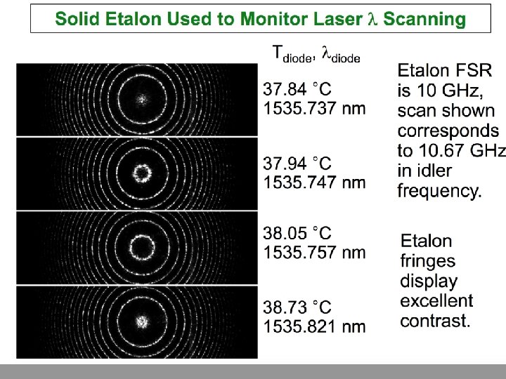
Etalon Output with Plane-Wave Illumination Scanning the input wavelength: Etalon Here, the free spectral range is the entire visible spectrum (this etalon would have to be very thin). Alternatively, one can use an air-spaced Fabry-Perot interferometer, and vary the spacing slightly, which wouldn’t change the FSR much, but would significantly vary the transmitted wavelengths. Or vary the etalon angle, which also changes the effective thickness and hence would do the same.
Focusing Light into an Etalon If we focus light into an etalon, different angles correspond to different path lengths. So different colors will experience constructive interference at different angles. Focused white -light beam Colorful rings! Etalon Multicolor input beam yields many rings. This figure on the left shows only one FSR, but typically many such ranges, or “orders, ” will be evident, like that on the right. Etalons have huge angular dispersion, dqout /dl 0.
More Etalon Rings for Narrowband Light Sources Narrowband UV lamp (many orders are visible) Three (four if you look very carefully) orders are visible. Cadmium lamp in a magnetic field (Zeeman splitting)
How to Use an Interferometer to Measure Wavelength Interferometers/etalons are the most accurate measures of wavelength available due to their huge dispersions. But their Free Spectral Range is limited, so they cannot distinguish between l and l + m dl. FSR, where m is any integer. So: 1. Measure the wavelength to within one Free Spectral Range using a grating or prism spectrometer to avoid the interferometer’s ambiguities. 2. Scan the spacing of the interferometer mirrors or the etalon angle until a transmission maximum occurs. 3. If greater accuracy is required, use another (thicker) interferometer or etalon with a FSR equal to the above line width and with an even smaller line width (i. e. , better accuracy).
Setup for Measuring Wavelength Use increasingly thick, higherspectral-resolution etalons. Thin etalon Thicker etalon FSR ≈ 1 nm FSR ≈ 0. 01 nm dl 0 LW ≈ Grating spectrometer dl 0 LW ≈ 1 nm The same setup can be used to filter white light into narrowband light. 0. 1 nm 0. 001 nm dl 0 LW ≈ 0. 001 nm Grating spectrometer
Other Applications of Fabry-Perot Interferometers and Etalons Money is now coated with interferometric inks to help foil counterfeiters. Notice the shade of the “ 20, ” which is shown from two different angles.
Anti-Reflection Coatings The lenses in the glasses on the right appear to be missing. They’re not! There anti-reflection coatings on both the front and back surface of each lens. Such coatings have been common on photography lenses and are now common on eyeglasses. Even TVs and my new watch are AR-coated!
Anti-Reflection Coatings Consider a beam incident on a glass substrate (n = ns) with a layer of material (n = nl) of thickness, h, on its surface. n 0 nl h ns It can be shown that the reflectance is (for such thin media, we need to go back to Maxwell’s equations): = 0 if So an AR-coating requires: layer and substrate
Multilayer Coatings Air n 0 n. L Typical laser mirrors and camera lenses use many l/4 layers, usually with alternating high and low refractive indices. The reflectance and transmittance vs. wavelength can be tailored to taste! n. H n. L n. H Glass substrate ns
Photonic crystals use interference to guide light—sometimes around corners! Borel, et al. , Opt. Expr. 12, 1996 (2004) Yellow indicates peak field regions. Augustin, et al. , Opt. Expr. , 11, 3284, 2003. Interference controls the path of light. Constructive interference occurs along the desired path.
Interference is easy when the light wave is a monochromatic plane wave. What if it’s not? For perfect sine waves, the two waves are either in phase or they’re not. What about a wave whose frequency drifts with time? E(t) E(t-t) t The waves could be in phase some of the time and out of phase at other times, varying rapidly. Remember that most optical measurements average over many cycles, so these variations will get averaged.
The Temporal Coherence Time A monochromatic plane wave is considered perfectly temporally coherent and hence has an infinite coherence time. The temporal coherence time is how long the beam remains sinusoidal in time at a single wavelength (and amplitude): Wave-fronts Temporal Coherence Time, tc tc Temporal coherence asks: what if we add many waves with different w’s for a given beam direction. x
The Spatial Coherence Length A plane wave is also considered perfectly spatially coherent and so has an infinite spatial coherence length and area. The spatial coherence length is the transverse distance over which the beam wave-fronts remain flat: Wave-fronts Spatial Coherence Length, xc xc x Since there are two transverse dimensions, the spatial coherence area, Ac = xc yc. Spatial coherence asks: what if we add waves of the same frequency but with different directions, that is, ’s.
Spatial and Temporal Coherence Beams can be coherent or only partially coherent (indeed, even incoherent) in both space and time. Only a plane wave is perfectly temporally and spatially coherent. Wave-fronts Spatial and Temporal Coherence xc tc Temporal Coherence; Spatial Incoherence xc tc Spatial Coherence; Temporal Incoherence Spatial and Temporal Incoherence xc tc xc x t, z tc
Spatial and Temporal Coherence: Another Picture The previous view was vs. time/frequency and space. Here we view vs. time/frequency and angle (kx/|k|). Spatial and Temporal Coherence; Spatial Incoherence Spatial Coherence; Temporal Incoherence Spatial and Temporal Incoherence E, x t, z
Two Very Different Light Waves with the Same Temporal Coherence Time Both Frequency Irradiance vs. time Locked phases Short pulse tc = 1/Dn Time Frequency Irradiance vs. time Random phases Light bulb tc = 1/Dn Time waves have the same spectral width. Note that, whether the modes are in phase or not, the irradiance spikes have about the same length: 1/Dn.
Two Very Different Light Waves with the Same Spatial Coherence Length Consider focusing rays in pairs with symmetrically propagating directions and add up all the fields at the focus, each yielding fringes with a spacing of l/2 sin(q), where q is the ray angle relative to the axis. Recall that: where: Allow the lens to become infinite in diameter in order to achieve the finest structure fringes and hence the smallest possible spot size at the focus. So q will range from 0 to 90º, and k’ will range from 0 to k.
Beams Crossing at an Angle with a Delay x Delaying one beam by d. L adds a phase delay k d. L to it. q z Delaying one of the beams with respect to the other shifts the fringes by k d. L.
The Tightest Possible Focus To find the focused field in this ideal case, integrate k’ from 0 to k: The tightest possible focused irradiance: The focused field and intensity FWHM ≈ l/2 E(x) l I(x) -l/2 x The focused irradiance can have a width no smaller than ≈ l/2.
Spatial Coherence: Interference in Space of Many Beams from a Perfect Lens We added up all the spatial fringes from crossing beams at the focus of an infinitely large perfect lens and found that, at best, we could focus a beam to a diameter of ~l/2 (= 2 p/Dkx): Irradiance Spatial E coherence where Dkx = 2 k = 2(2 p/l) = xc = 2 p/Dkx length: the total range of kx’s (the xc = 1/Dkx min is 0, and the max is 2 k) x The interference is coherent and constructive at x = 0, yielding a minimal-sized beam there of width 2 p/Dkx = 1/Dkx. And it is coherent and destructive elsewhere. Analogous to the coherence time!
Interference of Beams in Space from a Lousy Lens Now, what if the lens is very badly made, and all the spatial fringes are randomly out of phase with each other? The fringes now shift in phase by random amounts: Irradiance E xc = 1/Dkx x Analogous to the temporal case, the fluctuations are on a length scale similar to the perfect in-phase case, but are much less intense and there are many more spikes. Also analogously, the coherence length is: ~ 1/Dkx, where Dkx is the range of off-axis k’s (for this beam and also the perfect focus).
Stellar Interferometry Stars are too small to resolve using normal telescopes, but interferometry can see them by measuring their coherence properties. Stellar interferometers measure the spatial coherence using multiple detectors. They operate in the radio (where the signals are combined electronically) and, more recently, in the visible (where the beams are combined optically).
How to Make Spatially and Temporally Coherent Light from a Light Bulb A light bulb is neither spatially nor temporally coherent. temporally