Interfacing Data Converters DA converters Design an OP


: •")


, unmask")


- Slides: 21
Interfacing Data Converters
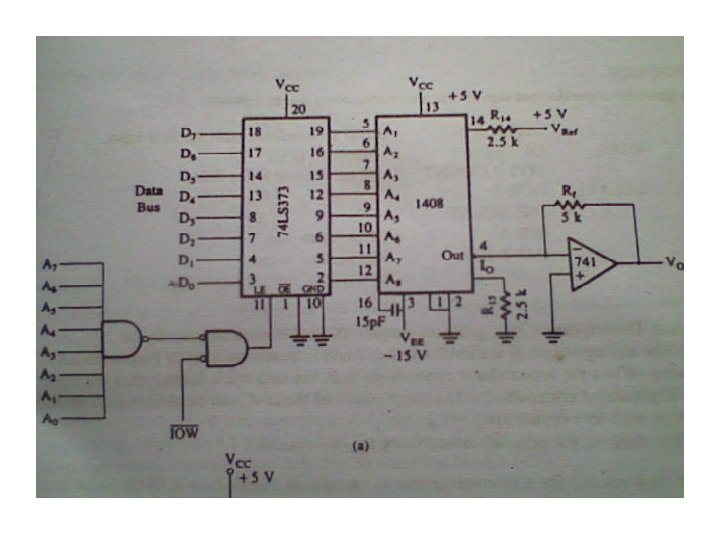
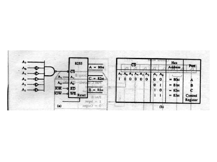
D/A converters • Design an O/P port with the address FFh to interface the 1408 D/A converter that is calibrated for 0 to 10 V range. • Write a program to generate a ramp. • calibrate the ciruit for bipolar range 5 V. • calculate the o/p for input 1000 0000.
• 1408 is TTL and CMOS compatible logic ckt. • 8 inputs • Labeling of LSB, MSB of data bus and the 1408 is opposite. (A 1 is MSB fo 1408) • 2 m. A reference current for full scale input. and two power supplies +5 and -15. • reference current is determined by R 14. • Output Io =
• Fo full scale input (D 7 to D 0 all =1): • The output is 1 LSB less than full scale reference source. The full-scale o/p voltage= 2 m. A(255/256)x 5 k =9. 961 V. • So, the ckt is designed for 0 to +10 V range.
program MVI A, 00 H DTOA: OUT FFH MVI B, COUNT DELAY: DCR B JNZ DELAY INR A JMP DTOA • Delay is necessary ; load AC with first i/p ; output to DAC ; Set B for delay ; next input ; go back to o/p – time needed for µP to execute an o/p loop is likely to be less than the settling time of DAC. – slope of the ramp can be varied by changing the delay.
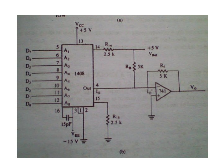
D/A in bipolar range • A 5 K resistor is connected between reference voltage Vref and the o/p in 4. • This will add 1 m. A to the o/p in opposite direction. therefore at input full scale the ouput voltage will be (2 m. A – 1 m. A)x. Rf = +5 V. I O’
• at input 0000 o/p is -5 V • at input 1000 0000 o/p is
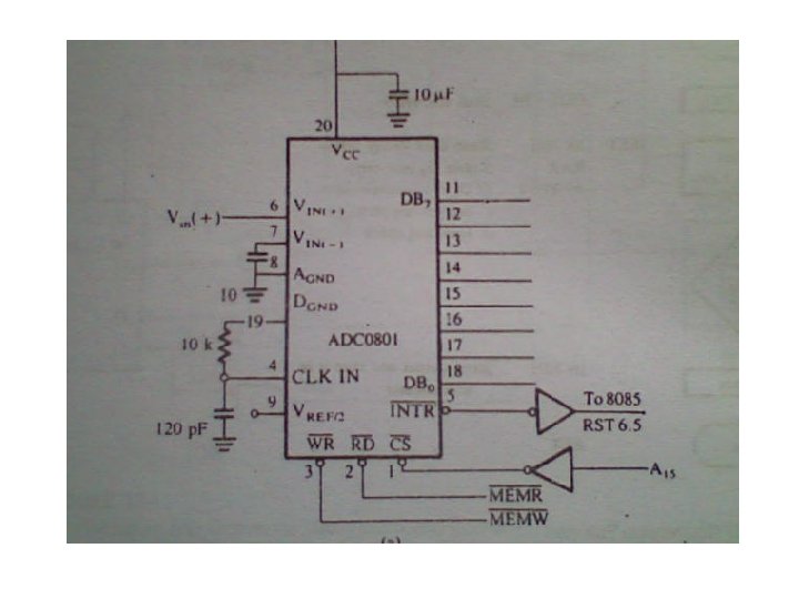
A/D converter • interface ADC 0801 using memory mapped IO and interrupt RST 6. 5. • Write interrupt service routine to read o/p data of the converter, store it in memory and continue to collect data for the specified number of times.
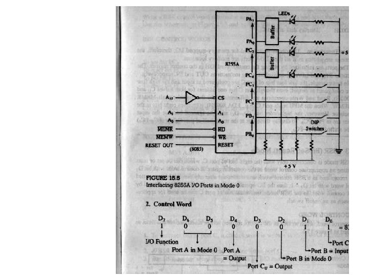
• ADC 0801 is CMOS 8 bit successive approcximation A/D converter. • output is 0 to +5 V. single supply. • two inputs for differential analog inputs • requires clock at input CLK IN. frequency range is 100 k. Hz to 800 k. Hz. has internal clock ckt. whose freq can is calculated = 1/(1. 1 RC) • it has 3 control signal: CS’, WR’ and RD’
• when WR’ makes transition from high to low, the internal SAR is reset, and the o/p lines go into high impedance. when WR’ makes transition from low to high, the conversion begins. When the conversion is complete, the INTR’ is asserted, and the data is placed on the o/p lines. • INTR’ is used to run a subroutine which reads data by asserting RD’ lines low. INTR’ si then reset. • Full scale o/p can be restricted to lower range of the inputs by using pin 9 (Vref/2).
Main program • the main program initializes the stack, enable the interrupt (EI), unmask RST 6. 5 (SIM), and initiate a conversion by writing to port 8000 H. The main program should include the initialization of the memory location for storing data ad the counter to count the readings. LXI SP, FFFFH LXI H, 7000 H MVI B, COUNT ; count bytes are to be read EI MVI A, 08 H ; load bit pattern to enable 7. 5, 6. 5, 5. 5 interrupts SIM STA 8000 H ; initiates the conversion
subroutine Service routing for RST 6. 5 at location 0034 H LDA 8000 H MOV M, A INX H DCR B STA 8000 H EI RNZ HLT ; read data ; store in memory ; points to next memory location ; next count ; Start next conversion ; Enable interrupt again ; return to main if B not zero ; End