Interfacing ADC and DAC with 8085 using 8255


 • Data")


![• Ex: 1. If data =00 H [0000], Vref= 10 V V 0=](https://slidetodoc.com/presentation_image_h/09a1243633a878b6ea3042c9ae132029/image-14.jpg "• Ex: 1. If data =00 H [0000], Vref= 10 V V 0=")


- Slides: 16
Interfacing ADC and DAC with 8085 using 8255
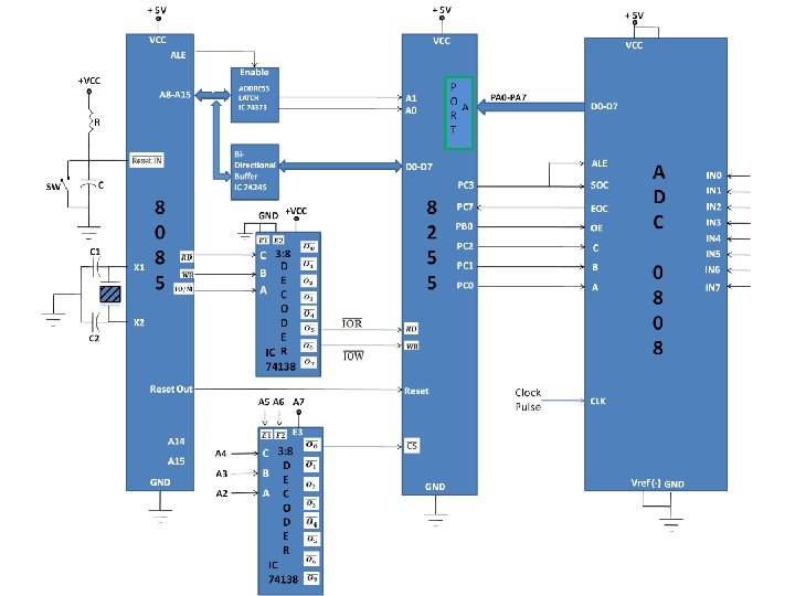
INTERFACING ADC WITH 8085 USING 8255
Interfacing ADC with 8085 using 8255 • Interface 8255 with 8085 that are explained before. • The ADC 0808 is 8 -channel 8 -bit ADC chip. • It has 8 analog inputs i. e. IN 0 -IN 7. • One of these channels is selected by sending address to a address line of ADC. The logic level and selected channel is as shown:
• The analog signal is connected to channel 3. • The digital equivalent data D 0 -D 7 is connected to PA 0 -PA 7 of Port A. • The PC 0, PC 1 and PC 2 lines of Port C are connected to channel select address lines of 8255. • PC 3 is connected to SOC (Start of conversion) and ALE signal (Input signal). • EOC (End of conversion) which is an output signal of 8255 connected to PC 7 of Port C.
Interfacing ADC with 8085 using 8255 • The PB 0 of Port B is connected to OE (Output Enable) input signal of ADC. • The control word format for above interface Is given as: • Control word= 98 H
Interfacing ADC with 8085 using 8255 • Data from channel selection: A high to low signal is applied for obtaining data from ADC. • Step – 1 • Data to Port C Address=0 BH (SOC= HIGH)
Interfacing ADC with 8085 using 8255 • Step – 2 • Data to Port C Address=03 H (SOC= LOW)
Interfacing ADC with 8085 using 8255 • Step – 3 Output Enable(OE) • Data to Port B Address=01 H (OE= HIGH)
PROGRAM CODE
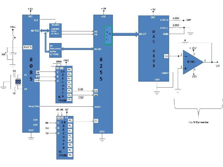
INTERFACING DAC WITH 8085 USING 8255
• Follow the initial 3 steps of interfacing of 8255 with 8085 that are explained before. • The DAC 0808 is 8 -bit digital to analog convertor IC. • It converts digital data into equivalent analog current. • Therefore I to V converter is used to convert analog output current of DAC to equivalent analog voltage. • PA 0 -PA 7 pins of Port A are connected to D 0 -D 7 pins of DAC. • In above DAC dual power supply of +/- 10 V is applied with reference voltage 10 V as shown in diagram. • According to theory of DAC Equivalent analog output is given as: V 0=Vref
• Ex: 1. If data =00 H [0000], Vref= 10 V V 0= 0 Volts. 2. If data is 80 H [10000000], Vref= 10 V V 0= 5 Volts.
• The control word format of 8255 for above interfacing is given as: • Control word = 80 H
PROGRAM CODE