Interaction Models 2 Activity Diagrams Extracted from textbook
: Activity Diagrams Extracted from textbook: Object Oriented Modeling and Design with")
Interaction Models (2): Activity Diagrams Extracted from textbook: Object Oriented Modeling and Design with UML M. Blaha, J. Rumbaugh

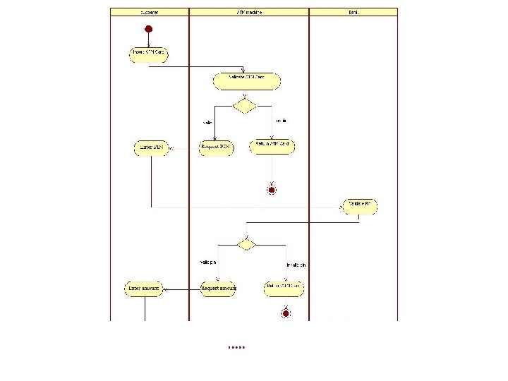
• An activity diagram shows the sequence of steps that make up a complex process such an algorithm or a workflow. • An activity diagram shows flow of control. It is like a traditional flowchart in that it shows the flow of control from one step to another step. • However, unlike a traditional flowchart, activity diagrams can show both sequential and concurrent flow of control. • Activity diagrams are most useful during the early stages of designing algorithms and workflows.
 • The steps of an activity diagrams are operations, specifically activities from")
Activity (1) • The steps of an activity diagrams are operations, specifically activities from the state model. • The purpose of an activity diagram is to show the steps within a complex activity and the sequencing constraints among them. • Some activities run forever until an outside event interrupt them. • But most activities eventually complete their work and terminate by themselves. The completion of an activity indicates that the next activity can be star ted
 • An activity may be decomposed into finer activities. • It is")
Activity (2) • An activity may be decomposed into finer activities. • It is important that the activities on an activity diagram be at the same level of details (level of abstraction).

 • If there is more than one successor to an activity, ach")
Branches (1) • If there is more than one successor to an activity, ach arrow ay be modeled with a condition in square brackets, for example: [failure] • All subsequent conditions are tested when an activity completes: – If one condition is satisfied its arrow indicates the next activity to perform. – If no condition is satisfied, the diagram is badly formed and the system will hang unless it is interrupted at some higher level – If multiple conditions are satisfied , only one successor executes but no guarantee which one it will be.
 • A diamond shows a branch into multiple successors but it means")
Branches (2) • A diamond shows a branch into multiple successors but it means the same thing as arrows leaving an activity symbol directly: – One incoming arrows, two or more outgoing arrows : Decision node – Several incoming arrows, one outgoing arrow: Merge node

Initiation/Termination • Initiation: – A solid circle with an outgoing arrow shows the starting point of an activity diagram. – When an activity diagram is activated , control starts at the solid circle and proceeds via the outgoing arrow towards the first activity. • Termination: – A solid circle surrounded by a hallow circle shows the termination point. It only has incoming arrows. – When control reaches this symbol, the overall activity is complete and execution of the activity diagrams ends.
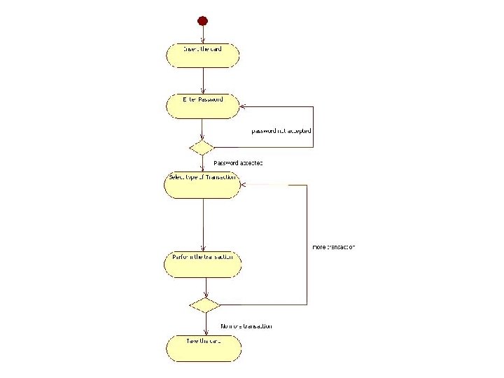

Concurrent Activities • Organizations and computer systems can perform more than one activity at the same time. • Example: one activity may be followed by another activity then split into several concurrent activities (a fork of control), and finally be combined into a single activity (a merge control) • A fork or merge is shown by a synchronization bar: – On a synchronization, control must be present on all the incoming activities, and control passes to all of the outgoing activities.

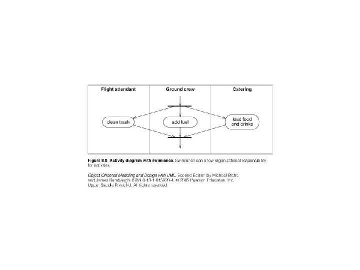
Special AD constructs • Swimlanes: – In a business model it is often useful to know which human organization is responsible for an activity. – Examples: sales, marketing, purchasing, production, engineering… – You can show such a partitioning with an activity diagram by diving it into columns: Each column is called a swimlane. – Often this kind of AD is called: Role Activity Diagram
- Slides: 13