
Inter Integrated Circuit I 2 C Cell Phone

- Slides: 10
Inter Integrated Circuit (I 2 C) Cell Phone Group members: Sean Womack Shunyue Yuan Chongwen Lu Zhuozhen Cai
What is I 2 C? The Inter Integrated Circuit (I 2 C) is a synchronous, multimaster, multi-slave, serial communication bus. An I 2 C includes: Two bidirectional open drain lines: SCL and SDA. ● ● Serial Clock Line (SCL) – align data by sending out 0/1, always controlled by the master. Serial Data Line (SDA) – transfer data https: //en. wikipedia. org/w/index. php? curid=44355704 Two roles for nodes: master and slave. ● ● Master node – generate the clock and initiate communication with slaves. Slave node – receive the clock and respond when addressed by the master. And a pull-up resistor. An example schematic of I 2 C https: //commons. wikimedia. org/w/index. php? curid=1472017
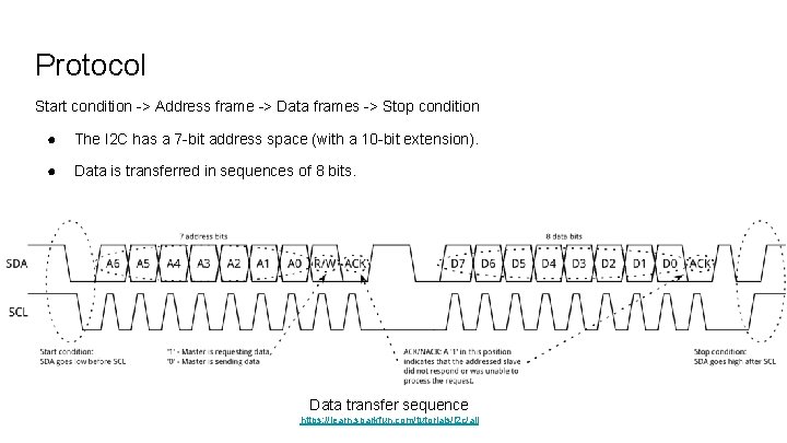
Protocol Start condition -> Address frame -> Data frames -> Stop condition ● The I 2 C has a 7 -bit address space (with a 10 -bit extension). ● Data is transferred in sequences of 8 bits. Data transfer sequence https: //learn. sparkfun. com/tutorials/i 2 c/all
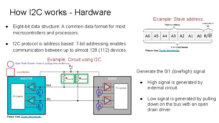
How I 2 C works - Hardware ● Eight-bit data structure: A common data format for most microcontrollers and processors. ● I 2 C protocol is address based: 7 -bit addressing enables communication between up to almost 128 (112) devices. Example: Slave address. Picture from Texas Instruments. Example: Circuit using I 2 C Generate the 0/1 (low/high) signal Picture from Texas Instruments. ● High signal is generated by external circuit. ● Low signal is generated by pulling down on the bus with an open drain driver.
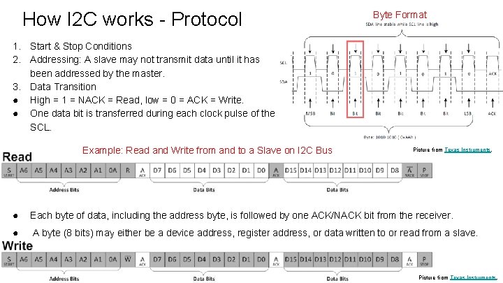
How I 2 C works - Protocol Byte Format 1. Start & Stop Conditions 2. Addressing: A slave may not transmit data until it has been addressed by the master. 3. Data Transition ● High = 1 = NACK = Read, low = 0 = ACK = Write. ● One data bit is transferred during each clock pulse of the SCL. Example: Read and Write from and to a Slave on I 2 C Bus Picture from Texas Instruments. ● Each byte of data, including the address byte, is followed by one ACK/NACK bit from the receiver. ● A byte (8 bits) may either be a device address, register address, or data written to or read from a slave. Picture from Texas Instruments.
Why to use I 2 C? Widely used for attaching lower-speed peripheral ICs to processors and microcontrollers in short-distance, intra-board communication ● Advantages ○ ○ ○ Flexibility: multi-master and multi-slave communication → add functionalities Simplicity: requires only two bidirectional wires, fewer pins and fewer PCB tracks Addressing feature: each device on the bus is independently addressed by software. … ● Limitations ○ Low speed, short distance, high power requirement, and need more space.
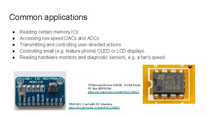
Common applications ● ● ● Reading certain memory ICs Accessing low-speed DACs and ADCs Transmitting and controlling user-directed actions Controlling small (e. g. feature phone) OLED or LCD displays. Reading hardware monitors and diagnostic sensors, e. g. a fan's speed. STMicroelectronics 24 C 08 - 8 Kbit Serial I²C Bus EEPROM https: //en. wikipedia. org/wiki/I%C 2%B 2 C 16 bit ADC Card with I 2 C Interface https: //en. wikipedia. org/wiki/I%C 2%B 2 C
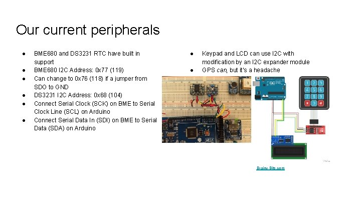
Our current peripherals ● ● ● BME 680 and DS 3231 RTC have built in support BME 680 I 2 C Address: 0 x 77 (119) Can change to 0 x 76 (118) if a jumper from SDO to GND DS 3231 I 2 C Address: 0 x 68 (104) Connect Serial Clock (SCK) on BME to Serial Clock Line (SCL) on Arduino Connect Serial Data In (SDI) on BME to Serial Data (SDA) on Arduino ● ● Keypad and LCD can use I 2 C with modification by an I 2 C expander module GPS can, but it’s a headache Brainy-Bits. com
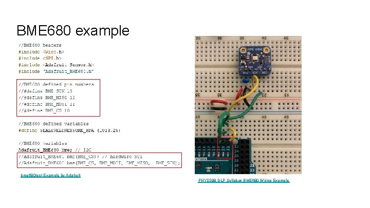
BME 680 example bme 680 test Example by Adafruit PHYS 398 DLP Syllabus BME 680 Wiring Example
References 1. 2. 3. 4. 5. 6. 7. I²C Wikipedia I 2 C - learn. sparkfun. com Adafruit Learn (BME 680) Advantages and Limitations of I 2 C Communication How I 2 C Communication Works & How To Use It with Arduino. (2015). TI Precision Labs - I 2 C: Hardware Overview. (2019), Texas Instruments. TI Precision Labs - I 2 C: Protocol Overview. (2019), Texas Instruments.