
Intensity Limitations Collimation in PS 2 SPS LHC
- Slides: 35
Intensity Limitations: Collimation in PS 2, SPS, LHC R. Assmann, CERN, AB/ABP Acknowledgements to the colleagues in the LHC Collimation Working Group which worked out and presented most of the results shown here: http: //www. cern. ch/lhc-collimation LUMI 05 Valencia, Spain October 20 th, 2006 RWA, 20/10/2006 1
Collimation Design Goals • High power, high intensity accelerators use collimators always to intercept and concentrate beam losses in well defined locations. • Depending on the accelerators several different design goals can apply: – Background control: Improve signal to noise ratio in particle and nuclear physics experiments (classical role in colliders). – Cleaning: Protect super-conducting magnets against direct beam losses and beam-induced quenches (e. g. LHC). – Protection: Shield sensitive equipment against beam-induced damage (instantaneous and long-term). – Radiation control: Localize and shield beam-induced radiation such to provide hands-on maintenance for rest of accelerator (e. g. SNS), control environmental impact, …. • For every accelerator all of these issues must be analyzed in detail. RWA, 20/10/2006 2
PS 2 and SPS Issues • Issues can be cleaning (if super-conducting), protection and radiation control. • Stored beam energy is much lower than in the LHC (~100 times): protection and cleaning are in principle easier than in the LHC. • However, important challenges compared to the LHC come from cycling: – Potentially much less stable beam (no stored beam equilibrium) potentially higher and faster losses… – If SC: Quench limit for cycling super-conducting magnets is less known (R&D issue). – Normalized aperture is changing during the cycle rapidly moving collimators, scrapers, … might be required (scraping before LHC injection). – Radiation problems can be more severe than in LHC: lower stored energy but many more cycles per day! • There should be no fundamental problem in collimation for PS 2 and SPS. Challenging but possible if collimation included into design from the start! Space! • Detailed analysis required to discuss about potential intensity limitations. I would suspect mostly limitations from radiation issues, if any at all. RWA, 20/10/2006 3
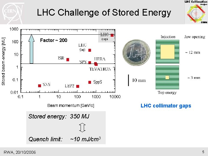
LHC Intensity Limitations • Focus of my talk on the predicted LHC limitations from collimation. • All the issues mentioned before were analyzed and studied for the LHC over the last 4 years: – Overall beam loss assumptions (1 st step). – Prediction of local losses. – Optimization of the collimation cleaning efficiency to protect SC magnets against quenches (including triplets background). – Placement and design of collimators to protect all equipment against damage. – Analysis and optimization of radiation impact (dose to personnel, environmental impact, radiation to electronics, …). • Gained an overall factor ~200 in performance reach (collimator robustness, absorption of cleaning-induced showers, losses in SC triplets, radiation to electronics, air activation, …). • Today concentrate on limitations after all this optimization… RWA, 20/10/2006 4
LHC Challenge of Stored Energy Factor ~ 200 LHC collimator gaps Stored energy: 350 MJ Quench limit: RWA, 20/10/2006 ~10 m. J/cm 3 5
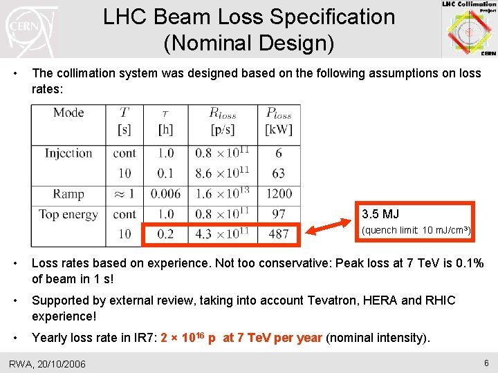
LHC Beam Loss Specification (Nominal Design) • The collimation system was designed based on the following assumptions on loss rates: 3. 5 MJ (quench limit: 10 m. J/cm 3) • Loss rates based on experience. Not too conservative: Peak loss at 7 Te. V is 0. 1% of beam in 1 s! • Supported by external review, taking into account Tevatron, HERA and RHIC experience! • Yearly loss rate in IR 7: 2 × 10¹⁶ p at 7 Te. V per year (nominal intensity). RWA, 20/10/2006 6
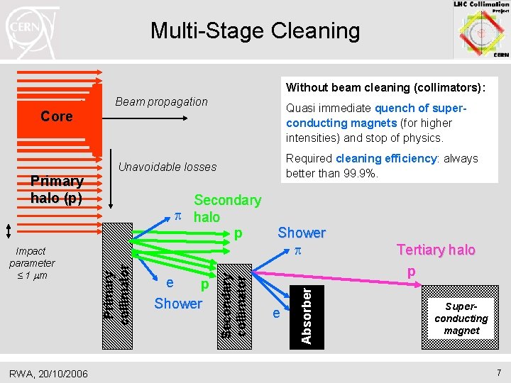
Multi-Stage Cleaning Without beam cleaning (collimators): Beam propagation Quasi immediate quench of superconducting magnets (for higher intensities) and stop of physics. Core RWA, 20/10/2006 Shower p e Absorber e p Shower Secondary collimator Impact parameter ≤ 1 mm Secondary p halo p Primary collimator Primary halo (p) Required cleaning efficiency: always better than 99. 9%. Unavoidable losses Tertiary halo p Superconducting magnet 7
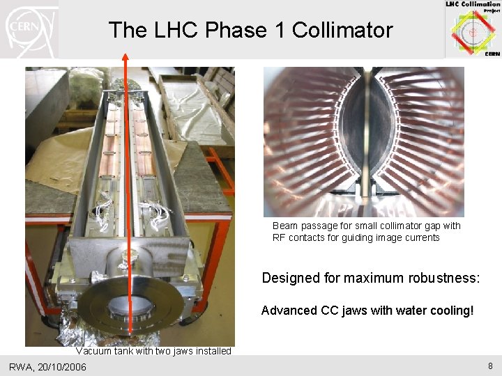
The LHC Phase 1 Collimator Beam passage for small collimator gap with RF contacts for guiding image currents Designed for maximum robustness: Advanced CC jaws with water cooling! Vacuum tank with two jaws installed RWA, 20/10/2006 8
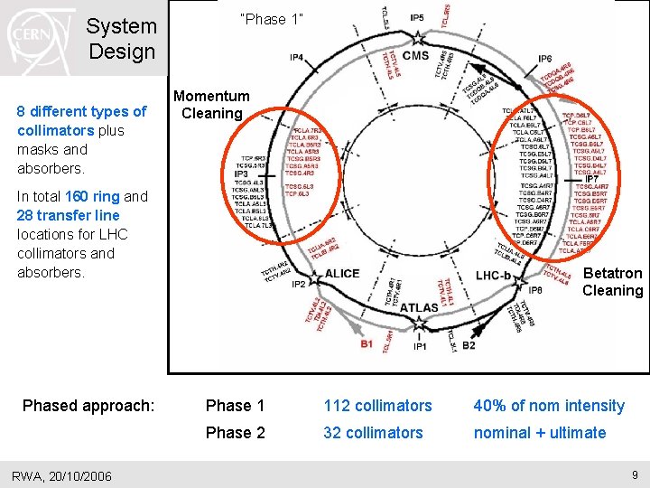
System Design 8 different types of collimators plus masks and absorbers. “Phase 1” Momentum Cleaning In total 160 ring and 28 transfer line locations for LHC collimators and absorbers. Phased approach: RWA, 20/10/2006 Betatron Cleaning Phase 1 112 collimators 40% of nom intensity Phase 2 32 collimators nominal + ultimate 9
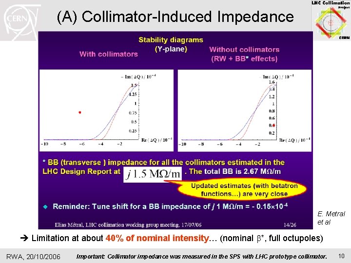
(A) Collimator-Induced Impedance E. Metral et al Limitation at about 40% of nominal intensity… (nominal b*, full octupoles) RWA, 20/10/2006 Important: Collimator impedance was measured in the SPS with LHC prototype collimator. 10
Potential Solutions Impedance Potential solutions are being considered: • Metallic secondary collimators (phase 2 design at SLAC and later CERN) lower electrical resistivity of collimator “wall”. • Increased chromaticity stabilize beams. • Low noise transverse feedback at 7 Te. V stabilize beams. • Triplet upgrade with larger aperture. Collimator gaps at 7 Te. V are a direct function of the triplet aperture and the b* larger gaps for all collimators. • Crystal-based collimation with increased particle deflection larger gaps for secondary collimators. • Non-linear collimation scheme larger gaps for secondary collimators. All approaches must be looked at, even if they now seem challenging! LARP/SLAC takes first steps towards construction of phase 2 collimator. RWA, 20/10/2006 11
Impedance and Chromaticity E. Metral et al RWA, 20/10/2006 12
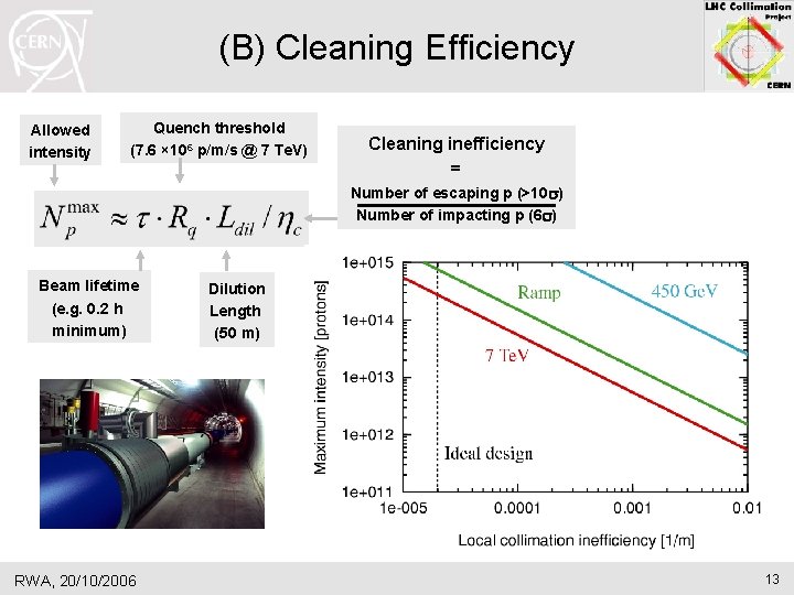
(B) Cleaning Efficiency Allowed intensity Quench threshold (7. 6 × 10⁶ p/m/s @ 7 Te. V) Cleaning inefficiency = Number of escaping p (>10 s) Number of impacting p (6 s) Beam lifetime (e. g. 0. 2 h minimum) RWA, 20/10/2006 Dilution Length (50 m) 13
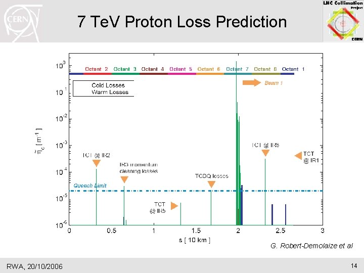
7 Te. V Proton Loss Prediction G. Robert-Demolaize et al RWA, 20/10/2006 14
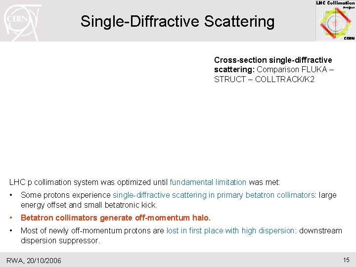
Single-Diffractive Scattering Cross-section single-diffractive scattering: Comparison FLUKA – STRUCT – COLLTRACK/K 2 LHC p collimation system was optimized until fundamental limitation was met: • Some protons experience single-diffractive scattering in primary betatron collimators: large energy offset and small betatronic kick. • Betatron collimators generate off-momentum halo. • Most of newly off-momentum protons are lost in first place with high dispersion: downstream dispersion suppressor. RWA, 20/10/2006 15
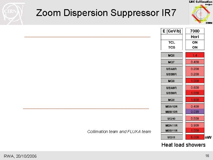
Zoom Dispersion Suppressor IR 7 Collimation team and FLUKA team m. W Heat load showers RWA, 20/10/2006 16
Predicted Limits from Betatron Cleaning Ph. D G. Robert-Demolaize • Quite a good margin at injection energy: Higher intensities can be handled. • Limitations at 7 Te. V to below nominal intensity. • Predictions are a function of minimum beam lifetime (peak loss of 0. 1% in 1 s) and the quench limit of SC magnets. Significant uncertainties! • Prediction is for ideal cleaning performance. Showers not included (Q 11)! RWA, 20/10/2006 17
Study Quench Limit I Dariusz Bocian RWA, 20/10/2006 18
Study Quench Limit II Dariusz Bocian RWA, 20/10/2006 19
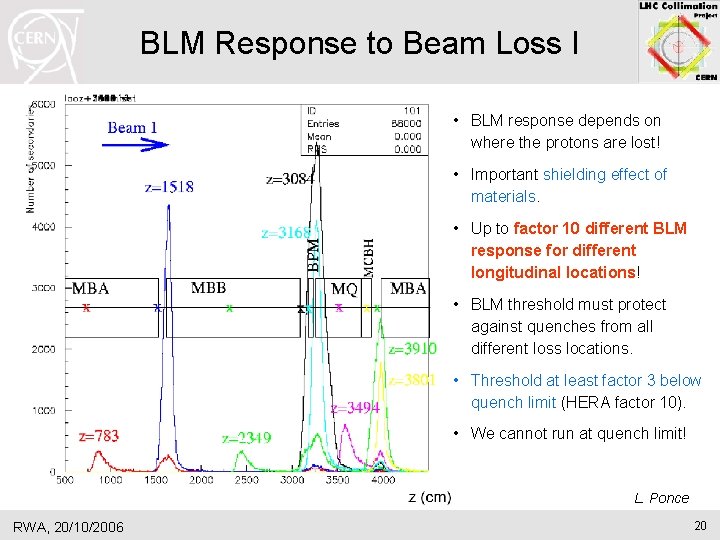
BLM Response to Beam Loss I • BLM response depends on where the protons are lost! • Important shielding effect of materials. • Up to factor 10 different BLM response for different longitudinal locations! • BLM threshold must protect against quenches from all different loss locations. • Threshold at least factor 3 below quench limit (HERA factor 10). • We cannot run at quench limit! L. Ponce RWA, 20/10/2006 20
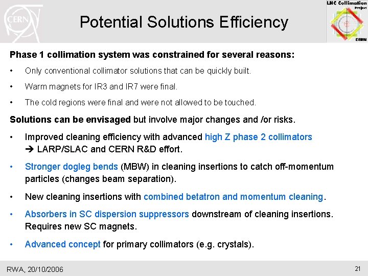
Potential Solutions Efficiency Phase 1 collimation system was constrained for several reasons: • Only conventional collimator solutions that can be quickly built. • Warm magnets for IR 3 and IR 7 were final. • The cold regions were final and were not allowed to be touched. Solutions can be envisaged but involve major changes and /or risks. • Improved cleaning efficiency with advanced high Z phase 2 collimators LARP/SLAC and CERN R&D effort. • Stronger dogleg bends (MBW) in cleaning insertions to catch off-momentum particles (changes beam separation). • New cleaning insertions with combined betatron and momentum cleaning. • Absorbers in SC dispersion suppressors downstream of cleaning insertions. Requires new SC magnets. • Advanced concept for primary collimators (e. g. crystals). RWA, 20/10/2006 21
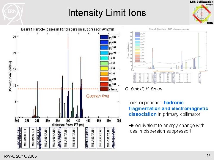
Intensity Limit Ions G. Bellodi, H. Braun Quench limit Ions experience hadronic fragmentation and electromagnetic dissociation in primary collimator equivalent to energy change with loss in dispersion suppressor! RWA, 20/10/2006 22
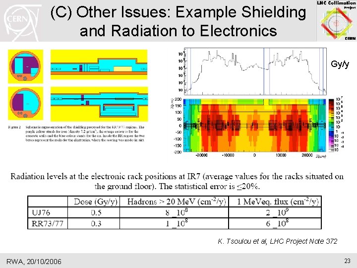
(C) Other Issues: Example Shielding and Radiation to Electronics Gy/y K. Tsoulou et al, LHC Project Note 372 RWA, 20/10/2006 23
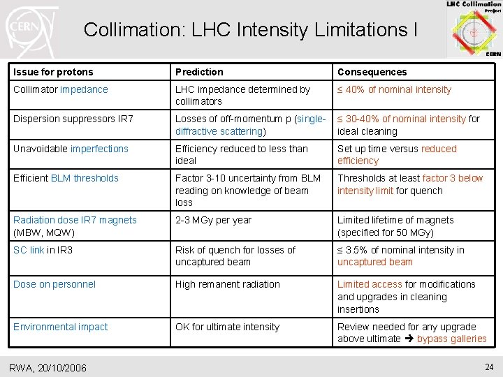
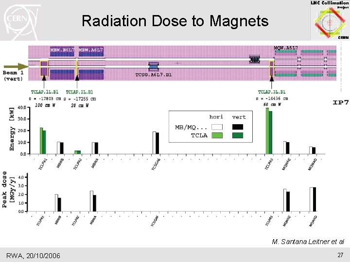
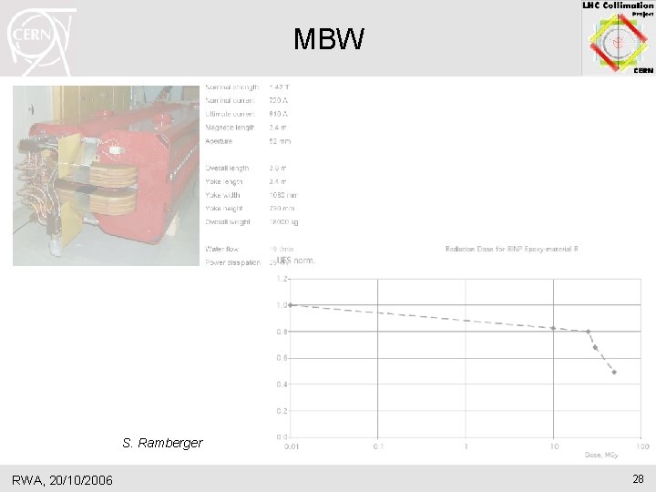
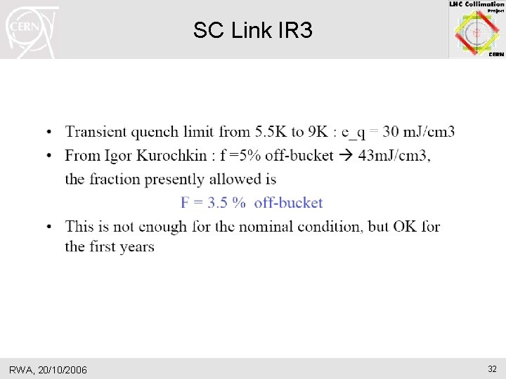
Collimation: LHC Intensity Limitations I Issue for protons Prediction Consequences Collimator impedance LHC impedance determined by collimators ≤ 40% of nominal intensity Dispersion suppressors IR 7 Losses of off-momentum p (singlediffractive scattering) ≤ 30 -40% of nominal intensity for ideal cleaning Unavoidable imperfections Efficiency reduced to less than ideal Set up time versus reduced efficiency Efficient BLM thresholds Factor 3 -10 uncertainty from BLM reading on knowledge of beam loss Thresholds at least factor 3 below intensity limit for quench Radiation dose IR 7 magnets (MBW, MQW) 2 -3 MGy per year Limited lifetime of magnets (specified for 50 MGy) SC link in IR 3 Risk of quench for losses of uncaptured beam ≤ 3. 5% of nominal intensity in uncaptured beam Dose on personnel High remanent radiation Limited access for modifications and upgrades in cleaning insertions Environmental impact OK for ultimate intensity Review needed for any upgrade above ultimate bypass galleries RWA, 20/10/2006 24
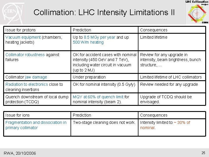
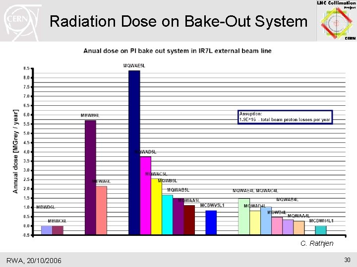
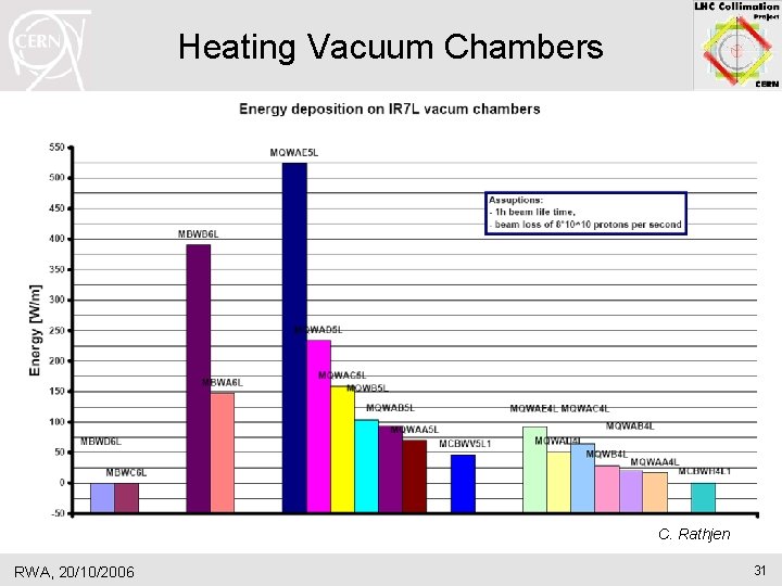
Collimation: LHC Intensity Limitations II Issue for protons Prediction Consequences Vacuum equipment (chambers, heating jackets) Up to 8. 5 MGy per year and up 500 W/m heating Limited lifetime Collimator robustness against failures OK for accident cases with nominal Review for any upgrade in intensity (450 Ge. V and 7 Te. V), intensity, beam brightness, bunch including water circuit in vacuum structure, … (up to 2 MJ) Collimator jaw damage Under preparation Limited lifetime of LHC collimators Radiation to electronics close to cleaning insertions OK for nominal intensity (0. 5 Gy/y) Review needed for any upgrade Quench downstream of local dump protection (TCDQ) MQY at 60% of quench limit for nominal intensity (beam 2). Upgrade of TCDQ should be envisaged. Issue for ions Prediction Consequences Fragmentation and dissociation in primary collimator Two-stage cleaning does not work. Intensity limited to ~ 30% of nominal. RWA, 20/10/2006 25
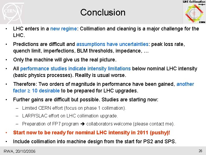
Conclusion • LHC enters in a new regime: Collimation and cleaning is a major challenge for the LHC. • Predictions are difficult and assumptions have uncertainties: peak loss rate, quench limit, imperfections, BLM thresholds, impedance, … • Only the machine will give us the real picture. • All performance studies indicate intensity limitations below nominal LHC intensity (basic physics processes). Reality is usual worse. • Therefore: Two orders of magnitude in performance have been gained, another factor ≥ 10 desirable to be prepared for LHC upgrades. • Further gains are difficult but possible. Studies are starting now: – Limited CERN effort (focus on phase 1 collimation). – LARP/SLAC effort on LHC collimation upgrade. – Preparation of FP 7 program collaborators welcome (please contact me). • Start now to be ready for nominal LHC intensity in 2011 (pushy)! • Include collimation into machine design from the start for PS 2 and SPS. RWA, 20/10/2006 26
Radiation Dose to Magnets M. Santana Leitner et al RWA, 20/10/2006 27
MBW S. Ramberger RWA, 20/10/2006 28
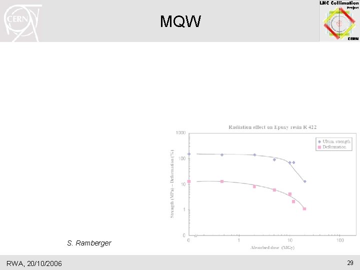
MQW S. Ramberger RWA, 20/10/2006 29
Radiation Dose on Bake-Out System C. Rathjen RWA, 20/10/2006 30
Heating Vacuum Chambers C. Rathjen RWA, 20/10/2006 31
SC Link IR 3 RWA, 20/10/2006 32
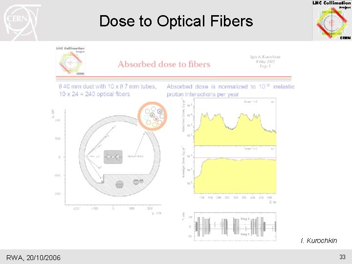
Dose to Optical Fibers I. Kurochkin RWA, 20/10/2006 33
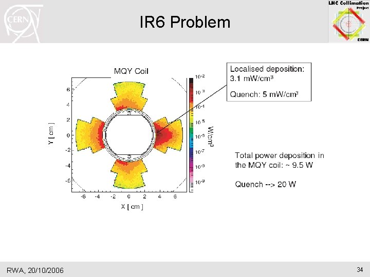
IR 6 Problem RWA, 20/10/2006 34
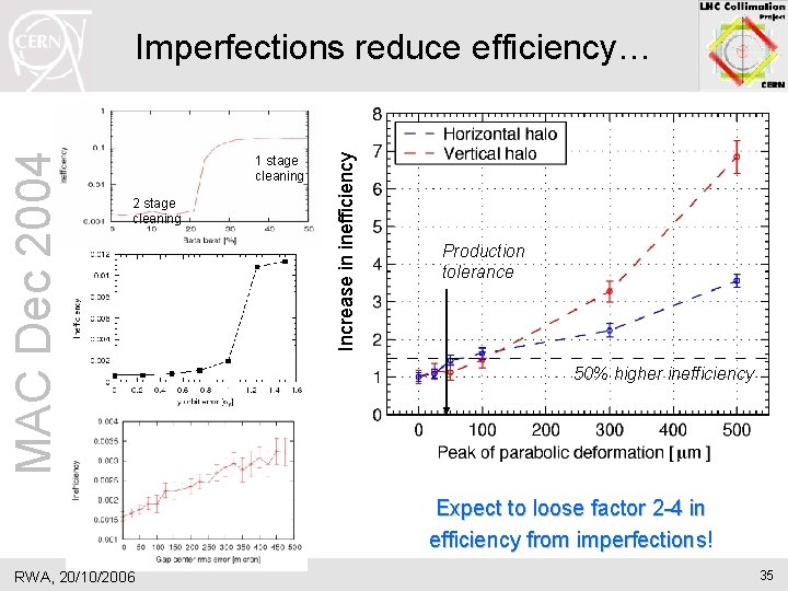
1 stage cleaning 2 stage cleaning Increase in inefficiency MAC Dec 2004 Imperfections reduce efficiency… Production tolerance 50% higher inefficiency Expect to loose factor 2 -4 in efficiency from imperfections! RWA, 20/10/2006 35