Intel Core i 7 Processor Nahalem 731 M

")
 Processor Performance 4")


 n n")
 n n n Desktop Computing n")


 Defects per")


 • Serves as an interface between software and hardware. •")

: 1 -address add A")


 Addressing Mode Register direct Immediate Displacement Register indirect Indexed")


 add dest, src 1, src")


 Accumulator + Index Registers (Manchester Mark")


 48 Reg DMem Ifetch Reg DMem Reg ALU O")


 57 Reg DMem Ifetch Reg ALU O r d")
 Instruction fetch 0 M u x")
 Instruction decode 0 M u x")
 Execution 0 M u x 1 IF/ID")
 Memory 0 M u x 1 IF/ID")
 Writeback 0 M u x 1 IF/ID")
 64 Instr 2 Instr 3")
 65 Instr 1 Instr 2 Stall")
 or r 8, r 1,")


")


 102")
- Slides: 102
Intel Core i 7 Processor Nahalem, 731 M xtor, 263 mm 2, 45 nm process, ~2008 2
CPU die comparison CPU Technology Cores Process AMD Epyc Rome (64 bit, SIMD, caches) 7 & 12 nm 32? Apple A 13 (iphone 11+) 7 nm 4 Haswell GT 3 4 C 22 nm Haswell GT 2 4 C GPU Transistor Die Size Count mm 2 39. 5 B 1088(!) GT 2 8. 5 B ~99 4 GT 3 ? ~264 22 nm 4 GT 2 1. 4 B 177 Haswell ULT GT 3 2 C 22 nm 2 GT 3 1. 3 B 181 Intel Ivy Bridge 4 C 22 nm 4 GT 2 1. 2 B 160 Intel Sandy Bridge E 6 C 32 nm 6 N/A 2. 27 B 435 Intel Sandy Bridge 4 C 32 nm 4 GT 2 995 M 216 Πηγές: cpu-world. com, anandtech. com, Wikipedia, κλπ. 3
(Single) Processor Performance 4
Outline n n What is Computer Architecture? Computer Instruction Sets – the fundamental abstraction n n 5 review and set up Dramatic Technology Advance Beneath the illusion – nothing is as it appears Computer Architecture Renaissance
What is “Computer Architecture”? Applications Operating System Compiler Instr. Set Proc. Firmware I/O system Instruction Set Architecture Datapath & Control Digital Design Circuit Design Layout & fab Semiconductor Materials Coordination of many levels of abstraction n Under a rapidly changing set of forces n Design, Measurement, and Evaluation n 6
Forces on Computer Architecture Technology Programming Languages Applications Computer Architecture Operating Systems 7 History
The Instruction Set: a Critical Interface software instruction set hardware n Properties of a good abstraction n n 8 Lasts through many generations (portability) Used in many different ways (generality) Provides convenient functionality to higher levels Permits an efficient implementation at lower levels
Single Processor Performance Move to multi-processor RISC 9
Current Trends in Architecture n Cannot continue to leverage Instruction-Level parallelism (ILP) n n New models for performance: n n 10 Single processor performance improvement ended in 2003 Data-level parallelism (DLP) Thread-level parallelism (TLP) Request-level parallelism (RLP) These require explicit restructuring of the application
Classes of Computers n Personal Mobile Device (PMD) n n n Desktop Computing n n Used for “Software as a Service (Saa. S)”, Paa. S, Iaa. S, etc. Emphasis on availability ($6 M/hour-downtime at Amazon. com!) and price-performance (power=80% of TCO!) Sub-class: Supercomputers, emphasis: floating-point performance and fast internal networks, and big data analytics Embedded (Io. T? ) Computers (19 billion in 2010) n 11 Emphasis on availability (very costly downtime!), scalability, throughput (20 million) Clusters / Warehouse Scale Computers n n Emphasis on price-performance (0. 35 billion) Servers n n e. g. smart phones, tablet computers (1. 8 billion sold 2010) Emphasis on energy efficiency and real-time Emphasis: price
Re-Defining Computer Architecture n “Old” view of computer architecture: n n Instruction Set Architecture (ISA) design i. e. decisions regarding: n n “Real” computer architecture: n n 12 Registers#, memory addressing, addressing modes, instruction operands, available operations, control flow instructions, instruction encoding Specific requirements of the target machine Design to maximize performance within constraints: cost, power, and availability Includes ISA, microarchitecture, hardware Security? Quality of Service?
Trends in Technology n Integrated circuit technology n n n DRAM capacity: 25 -40%/year (slowing) Flash capacity: 50 -60%/year n n 15 -20 X cheaper/bit than DRAM Magnetic disk technology: 40%/year n n 13 Transistor density: 35%/year Die size: 10 -20%/year Integration overall: 40 -55%/year 15 -25 X cheaper/bit then Flash 300 -500 X cheaper/bit than DRAM
Bandwidth and Latency n n 14 Bandwidth or throughput n Total work done in a given time n 10, 000 -25, 000 X improvement for processors over the 1 st milestone n 300 -1200 X improvement for memory and disks over the 1 st milestone Latency or response time n Time between start and completion of an event n 30 -80 X improvement for processors over the 1 st milestone n 6 -8 X improvement for memory and disks over the 1 st milestone
Bandwidth and Latency Log-log plot of bandwidth and latency milestones 15
Transistors and Wires n Feature size n n n Minimum size of transistor or wire in x or y dimension 10 microns in 1971 to. 032 microns in 2011 Transistor performance scales linearly n n n 16 Wire delay does not improve with feature size! Integration density scales quadratically Linear performance and quadratic density growth present a challenge and opportunity, creating the need for computer architect!
Power and Energy n n Problem: Get power in, get power out Thermal Design Power (TDP) n n n 17 Characterizes sustained power consumption Used as target for power supply and cooling system Lower than peak power, higher than average power consumption Envelop? Clock rate can be reduced dynamically to limit power consumption Energy per task is often a better measurement
Dynamic Energy and Power n Dynamic energy n n Transistor switch from 0 -> 1 or 1 -> 0 f x Capacitive load x Voltage 2 n n For f= ½ we get ½ x Capacitive load x Voltage 2 n n ½ x Capacitive load x Voltage 2 x Frequency switched n 18 Typical assumption for activity factor is ½ Dynamic power n n f is activity factor Again, assumes activity factor is ½ Reducing clock rate reduces power, not energy
Power n n 19 Intel 80386 consumed ~ 2 W 3. 3 GHz Intel Core i 7 consumes 130 W Heat must be dissipated from 1. 5 x 1. 5 cm chip This is the limit of what can be cooled by air
Reducing Power n Techniques for reducing power: n n n Do nothing Dynamic Voltage Scaling (DVS) Dynamic Frequency Scaling (DFS) Dynamic Voltage-Frequency Scaling (DVFS) Low power state for DRAM, disks n n 20 Sleep modes Overclocking, then turn off cores (!!!)
Static Power n Static power consumption n n The new primary evaluation for design innovation n n 21 Currentstatic x Voltage Scales with number of transistors To reduce: power gating Race-to-halt Tasks per joule Performance per watt
Trends in Cost driven down by learning curve n Yield n DRAM: price closely tracks cost n Microprocessors: price depends on volume n 22 10% less for each doubling of volume
Integrated Circuit Cost n n n 23 Integrated circuit Bose-Einstein formula (!) Defects per unit area = 0. 016 -0. 057 defects per square cm (2010) N = process-complexity factor = 11. 5 -15. 5 (40 nm, 2010) The manufacturing process dictates the wafer cost, wafer yield and defects per unit area The architect’s design affects the die area, which in turn affects the defects and cost per die
Dependability n Systems alternate between two states of service with respect to Service Level Agreements/Objectives (SLA/SLO): n n n Module reliability: n n 24 Service accomplishment, where service is delivered as specified by SLA Service interruption, where the delivered service is different from the SLA Mean time to failure (MTTF) Mean time to repair (MTTR) Mean time between failures (MTBF) = MTTF + MTTR Availability = MTTF / MTBF
Measuring Performance n Typical performance metrics: n n n Speedup of X relative to Y n n n Wall clock time: includes all system overheads CPU time: only computation time Benchmarks n n 25 Execution time. Y / Execution time. X Execution time n n Response time Throughput Kernels (e. g. matrix multiply) Toy programs (e. g. sorting) Synthetic benchmarks (e. g. Dhrystone) Benchmark suites (e. g. SPEC 06 fp, TPC-C)
Principles of Computer Design n Take Advantage of Parallelism n n Principle of Locality n n Reuse of data and instructions Focus on the Common Case!!! n 26 e. g. multiple processors, disks, memory banks, pipelining, multiple functional units Amdahl’s Law
Amdahl’s Law Best you could ever hope to get: 27 F=0. 1 => S ~= 1. 1 F=0. 5 => S = 2 F=0. 9 => S = 10
Principles of Computer Design n 28 The Processor Performance Equation
Principles of Computer Design n 29 Different instruction types having different CPIs
Instruction Set Architecture (ISA) • Serves as an interface between software and hardware. • Provides a mechanism by which the software tells the hardware what should be done. High level language code : C, C++, Java, Fortran, compiler Assembly language code: architecture specific statements assembler Machine language code: architecture specific bit patterns software instruction set hardware 30
Instruction Set Design Issues n Instruction set design issues include: n n n 31 Where are operands stored? n registers, memory, stack, accumulator How many explicit operands are there? n 0, 1, 2, or 3 How is the operand location specified? n register, immediate, indirect, . . . What type & size of operands are supported? n byte, int, float, double, string, vector. . . What operations are supported? n add, sub, mul, move, compare. . .
Classifying ISAs Accumulator (before 1960, e. g. 68 HC 11): 1 -address add A Stack (1960 s to 1970 s): 0 -address add acc ¬ acc + mem[A] tos ¬ tos + next Memory-Memory (1970 s to 1980 s): 2 -address 3 -address add A, B, C mem[A] ¬ mem[A] + mem[B] mem[A] ¬ mem[B] + mem[C] Register-Memory (1970 s to present, e. g. 80 x 86): 2 -address add R 1, A load R 1, A R 1 ¬ R 1 + mem[A] R 1 ¬ mem[A] Register-Register (Load/Store/RISC) (‘ 60 s to present, e. g. MIPS): 3 -address 32 add R 1, R 2, R 3 load R 1, R 2 store R 1, R 2 R 1 ¬ R 2 + R 3 R 1 ¬ mem[R 2] mem[R 1] ¬ R 2
Operand Locations in Four ISA Classes GPR 33
Code Sequence C = A + B for 4 ISAs Stack Accumulator Push A Push B Add Pop C Load A Add B Store C memory acc = acc + mem[C] 34 Register (register-memory) Load R 1, A Add R 1, B Store C, R 1 memory R 1 = R 1 + mem[C] Register (loadstore) Load R 1, A Load R 2, B Add R 3, R 1, R 2 Store C, R 3 = R 1 + R 2
Types of Addressing Modes (VAX) Addressing Mode Register direct Immediate Displacement Register indirect Indexed Direct Memory Indirect Autoincrement Example Action 1. Add R 4, R 3 R 4 <- R 4 + R 3 2. Add R 4, #3 R 4 <- R 4 + 3 3. Add R 4, 100(R 1) R 4 <- R 4 + M[100 + R 1] 4. Add R 4, (R 1) R 4 <- R 4 + M[R 1] 5. Add R 4, (R 1 + R 2) R 4 <- R 4 + M[R 1 + R 2] 6. Add R 4, (1000) R 4 <- R 4 + M[1000] 7. Add R 4, @(R 3) R 4 <- R 4 + M[M[R 3]] 8. Add R 4, (R 2)+ R 4 <- R 4 + M[R 2] R 2 <- R 2 + d 9. Autodecrement Add R 4, (R 2)R 4 <- R 4 + M[R 2] R 2 <- R 2 - d 10. Scaled Add R 4, 100(R 2)[R 3] R 4 <- R 4 + M[100 + R 2 + R 3*d] n [Clark and Emer]: modes 1 -4 => 93% of all operands on the VAX!!! 35
Types of Operations n n n n 36 Arithmetic and Logic: Data Transfer: Control System Floating Point Decimal String Graphics AND, ADD MOVE, LOAD, STORE BRANCH, JUMP, CALL OS CALL, VM ADDF, MULF, DIVF ADDD, CONVERT MOVE, COMPARE (DE)COMPRESS
MIPS Instructions n n n All instructions exactly 32 bits wide Different formats for different purposes Similarities in formats ease implementation 31 31 31 37 6 bits 5 bits op rs rt rd 6 bits 5 bits 16 bits op rs rt offset 6 bits shamt funct 6 bits 26 bits op address 0 0 R-Format I-Format J-Format 0
MIPS Instruction Types n Arithmetic & Logical - manipulate data in registers add $s 1, $s 2, $s 3 or $s 3, $s 4, $s 5 n Data Transfer - move register data to/from memory load & store lw $s 1, 100($s 2) sw $s 1, 100($s 2) n $s 1 = $s 2 + $s 3 = $s 4 OR $s 5 $s 1 = Memory[$s 2 + 100] = $s 1 Branch - alter program flow beq $s 1, $s 2, 25 4*25 if ($s 1==$s 1) PC = PC + 4 + else PC = PC + 4 38
MIPS Arithmetic & Logical Instructions n Instruction usage (assembly) add dest, src 1, src 2 sub dest, src 1, src 2 and dest, src 1, src 2 n Instruction characteristics n n Always 3 operands: destination + 2 sources Operand order is fixed Operands are always general purpose registers Design Principles: n n 39 dest=src 1 + src 2 dest=src 1 - src 2 dest=src 1 AND src 2 Design Principle 1: Simplicity favors regularity Design Principle 2: Smaller is faster
Arithmetic & Logical Instructions 31 n n n 40 5 bits op rs rt rd 5 bits 6 bits shamt funct 0 Used for arithmetic, logical, shift instructions n n 6 bits op: Basic operation of the instruction (opcode) rs: first register source operand rt: second register source operand rd: register destination operand shamt: shift amount (more about this later) funct: function - specific type of operation Also called “R-Format” or “R-Type” Instructions
Arithmetic & Logical Instructions n n Machine language for add $8, $17, $18 See reference card for op, funct values 31 6 bits 5 bits op rs rt rd 0 17 18 8 5 bits 6 bits shamt funct 0 32 000000 10001 10010 01000 00000 100000 41 0 Decimal Binary
MIPS Data Transfer Instructions n n Transfer data between registers and memory Instruction format (assembly) lw $dest, offset($addr) sw $src, offset($addr) n Uses: n n 42 load word store word Accessing a variable in main memory Accessing an array element
Evolution of Instruction Sets Single Accumulator (EDSAC 1950) Accumulator + Index Registers (Manchester Mark I, IBM 700 series 1953) Separation of Programming Model from Implementation High-level Language Based (Stack) (B 5000 1963) Concept of a Family (IBM 360 1964) General Purpose Register Machines Complex Instruction Sets (Vax, Intel 432 1977 -80) Intel x 86 Load/Store Architecture (CDC 6600, Cray 1 1963 -76) RISC (MIPS, Sparc, HP-PA, IBM RS 6000, 1987) ARM, Risc. V 43
Components of Performance CPU time = Seconds Program Cycles x Instruction CPI Program Instr. count Χ Compiler Χ Χ Instruction Set Architecture (ISA) Οργάνωση X Χ Χ X Χ Τεχνολογία 44 = Instructions x Program Seconds Cycle Clock rate CPI Χ Inst count Cycle time
What’s a Clock Cycle? Latch or register n n 45 combinational logic Old days: 10 FO 4 levels of gates (fan-out-of-four) Today: determined by numerous time-of-flight issues + gate delays n clock propagation, wire lengths, drivers n Still ~10 -20…
Integrated Approach What really matters is the functioning of the complete system, I. e. hardware, runtime system, compiler, and operating system In networking, this is called the “End to End argument” n Computer architecture is not just about transistors, individual instructions, or particular implementations n Original RISC projects replaced complex instructions with a compiler + simple instructions 46
How to achieve better performance? n ISA is a contract! n But: underneath the ISA illusion…. n n Do more things at once (i. e. in parallel) Do the things that you do faster This is what computer architecture is all about! 47
Example Pipelining Time (clock cycles) 48 Reg DMem Ifetch Reg DMem Reg ALU O r d e r Ifetch ALU I n s t r. ALU Cycle 1 Cycle 2 Cycle 3 Cycle 4 Cycle 5 Cycle 6 Cycle 7 Ifetch Reg Reg DMem Reg
The Memory Abstraction n n Association of <name, value> pairs n typically named as byte addresses n often values aligned on multiples of size Sequence of Reads and Writes Write binds a value to an address Read of addr returns most recently written value bound to that address command (R/W) address (name) data (W) data (R) done 49
Levels of the Memory Hierarchy Capacity Access Time Cost CPU Registers 100 s Bytes << 1 s ns Cache 10 s-100 s K Bytes ~1 ns $1 s/ MByte Main Memory M Bytes 100 ns- 300 ns $< 1/ MByte Disk 10 s G Bytes, 10 ms (10, 000 ns) $0. 001/ MByte Tape infinite sec-min $0. 0014/ MByte Upper Level Staging Xfer Unit faster Registers Instr. Operands prog. /compiler 1 -8 bytes Cache Blocks cache cntl 8 -128 bytes Memory OS Pages. NVRAM (SCM, 512 -4 K SSD) bytes Disk Files Tape user/operator Mbytes Lower Level circa 1995 numbers 50 Larger
The Principle of Locality n The Principle of Locality: n n Two Different Types of Locality: n n n Program access a relatively small portion of the address space at any instant of time Temporal Locality (Locality in Time): If an item is referenced, it will tend to be referenced again soon (e. g. , loops, reuse) Spatial Locality (Locality in Space): If an item is referenced, items whose addresses are close by tend to be referenced soon (e. g. , straightline code, array access) Last 30 years, HW relied on locality for speed P 51 $ MEM
The Cache Design Space n Several interacting dimensions n n n Cache Size cache size block size associativity replacement policy write-through vs write-back Associativity Block Size n The optimal choice is a compromise n depends on access characteristics n n 52 workload use (I-cache, D-cache, TLB) depends on technology / cost Simplicity often wins Bad Good Factor A Less Factor B More
Is it all about memory system design? 53
Is it all about memory system design? Nahalem, ~2008 54
Memory Abstraction and Parallelism n n Maintaining the illusion of sequential access to memory What happens when multiple processors access the same memory at once? n Do they see a consistent picture? Pn P 1 $ $ Mem Interconnection network Mem n n 55 Mem Processing and processors embedded in the memory? Does/should the SW know about hierarchy? NUMA! $
5 -Stage Pipelined Datapath Instruction Fetch Execute Addr. Calc Instr. Decode Reg. Fetch Next SEQ PC Adder Zero? RS 1 Imm IR ← Mem[PC] PC ← PC + 4 RD A ← Reg[IRrs] B ← Reg[IRrt] 56 RD rslt ← A op. IRop B RD Mem[rslt] MUX Sign Extend MEM/WB Data Memory EX/MEM MUX ALU MUX ID/EX Reg File IF/ID Memory Address RS 2 WB Data 4 Write Back MUX Next PC Memory Access Reg[IRrd]←WB
Διάγραμμα χρονισμού Time (clock cycles) 57 Reg DMem Ifetch Reg ALU O r d e r Ifetch ALU I n s t r. Cycle 6 Cycle 7 ALU Cycle 1 Cycle 2 Cycle 3 Cycle 4 Cycle 5 Reg Reg DMem Reg
Παράδειγμα για την εντολή lw: Instruction Fetch (IF) Instruction fetch 0 M u x 1 IF/ID EX/MEM ID/EX MEM/WB Add Add result 4 PC Address Instruction memory Instruction Shift left 2 Read register 1 Read data 1 Read register 2 Registers Read Write data 2 register Write data 0 M u x 1 Zero ALU result Address Data memory Write data 16 58 Sign extend 32 Read data 1 M u x 0
Παράδειγμα για την εντολή lw: Instruction Decode (ID) Instruction decode 0 M u x 1 IF/ID EX/MEM ID/EX MEM/WB Add Add result 4 PC Address Instruction memory Instruction Shift left 2 Read register 1 Read data 1 Read register 2 Registers Read Write data 2 register Write data 0 M u x 1 Zero ALU result Address Data memory Write data 16 59 Sign extend 32 Read data 1 M u x 0
Παράδειγμα για την εντολή lw: Execution (EX) Execution 0 M u x 1 IF/ID EX/MEM ID/EX MEM/WB Add Add result 4 PC Address Instruction memory Instruction Shift left 2 Read register 1 Read data 1 Read register 2 Registers Read Write data 2 register Write data 0 M u x 1 Zero ALU result Address Data memory Write data 16 60 Sign extend 32 Read data 1 M u x 0
Παράδειγμα για την εντολή lw: Memory (MEM) Memory 0 M u x 1 IF/ID EX/MEM ID/EX MEM/WB Add Add result 4 PC Address Instruction memory Instruction Shift left 2 Read register 1 Read data 1 Read register 2 Registers Read Write data 2 register Write data 0 M u x 1 Zero ALU result Address Data memory Write data 16 61 Sign extend 32 Read data 1 M u x 0
Παράδειγμα για την εντολή lw: Writeback (WB) Writeback 0 M u x 1 IF/ID EX/MEM ID/EX MEM/WB Add Add result 4 PC Address Instruction memory Instruction Shift left 2 Read register 1 Read data 1 Read register 2 Registers Read Write data 2 register Write data 0 M u x 1 Zero ALU result Address Data memory Write data 16 62 Sign extend 32 Read data 1 M u x 0
Structural hazard: ένα διαθέσιμο memory port Time (clock cycles) 64 Instr 2 Instr 3 Instr 4 DMem Ifetch Reg ALU Instr 1 Reg ALU Ifetch ALU O r d e r Load ALU I n s t r. ALU Cycle 1 Cycle 2 Cycle 3 Cycle 4 Cycle 5 Cycle 6 Cycle 7 Reg Reg DMem Reg
Structural hazard: επίλυση με stall Time (clock cycles) 65 Instr 1 Instr 2 Stall Instr 3 Reg DMem Ifetch Reg ALU Ifetch Bubble Reg Bubble Ifetch Reg DMem Bubble Reg Bubble ALU O r d e r Load ALU I n s t r. ALU Cycle 1 Cycle 2 Cycle 3 Cycle 4 Cycle 5 Cycle 6 Cycle 7 Bubble DMem Reg
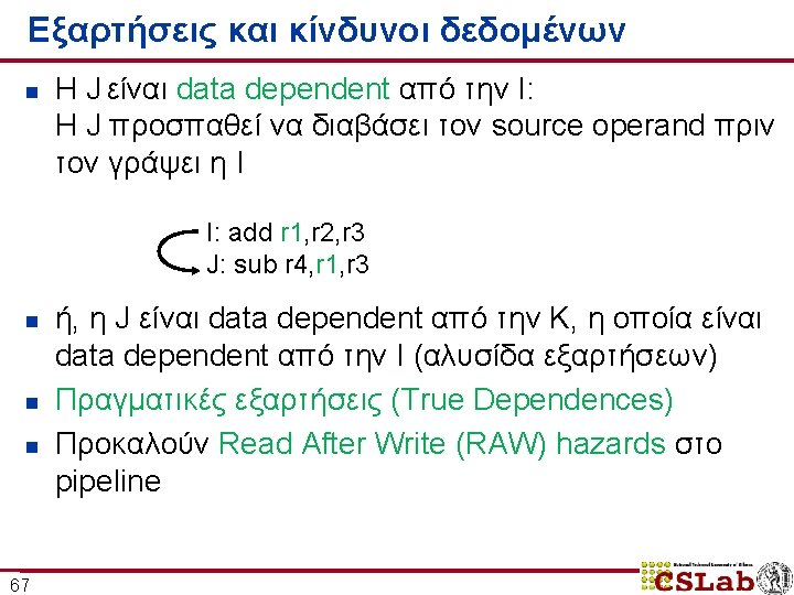
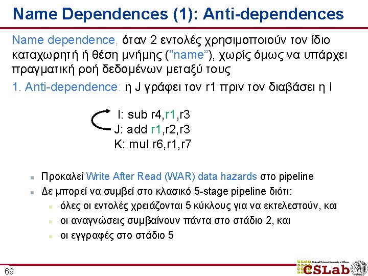
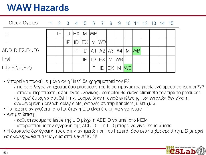
Παράδειγμα data hazard στον r 1 Time (clock cycles) or r 8, r 1, r 9 xor r 10, r 11 66 Reg DMem Ifetch Reg ALU and r 6, r 1, r 7 WB ALU O r d e r sub r 4, r 1, r 3 Ifetch MEM ALU add r 1, r 2, r 3 EX ALU I n s t r. ID/RF ALU IF Reg Reg DMem Reg
Προώθηση DMem Ifetch Reg ALU and r 6, r 1, r 7 Reg ALU sub r 4, r 1, r 3 Ifetch ALU O r d e r add r 1, r 2, r 3 ALU I n s t r. ALU Time (clock cycles) or r 8, r 1, r 9 xor r 10, r 11 • μειώνονται τα RAW hazards 71 Reg Reg DMem Reg
Αλλαγές στο hardware για την υποστήριξη προώθησης Next. PC mux Immediate Προώθηση ΕΧ->ΕΧ, ΜΕΜ->ΕΧ 72 MEM/WR EX/MEM ALU mux ID/EX Registers Data Memory
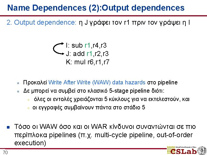
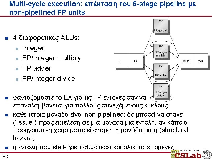
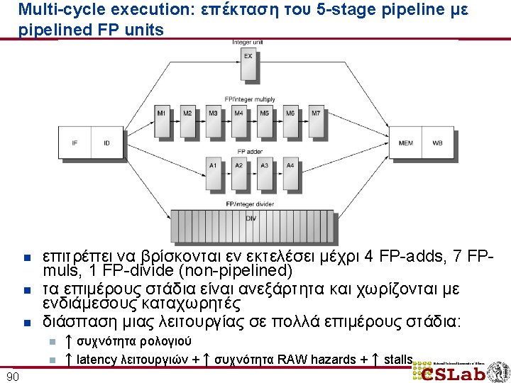
Προώθηση ΜΕΜ->ΜΕΜ or r 8, r 6, r 9 xor r 10, r 9, r 11 73 DMem Ifetch Reg ALU sw r 4, 12(r 1) Reg ALU lw r 4, 0(r 1) Ifetch ALU O r d e r add r 1, r 2, r 3 ALU I n s t r. ALU Time (clock cycles) Reg Reg DMem Reg
Η προώθηση δεν δουλεύει πάντα! and r 6, r 1, r 7 74 or r 8, r 1, r 9 Reg DMem Ifetch Reg Reg DMem ALU O r d e r sub r 4, r 1, r 6 Ifetch ALU lw r 1, 0(r 2) ALU I n s t r. ALU Time (clock cycles) Reg DMem Reg
Η προώθηση δεν δουλεύει πάντα! and r 6, r 1, r 7 75 or r 8, r 1, r 9 Reg DMem Ifetch Reg Bubble DMem Ifetch Bubble Reg Bubble Ifetch Reg Reg DMem ALU O r d e r sub r 4, r 1, r 6 Ifetch ALU lw r 1, 0(r 2) ALU I n s t r. ALU Time (clock cycles) Reg DMem
Αναδιάταξη εντολών για αποφυγή RAW hazards Πώς μπορούμε να παράγουμε γρηγορότερο κώδικα assembly για τις ακόλουθες πράξεις? a = b + c; d = e – f; Slow code: LW LW ADD SW LW LW SUB SW 76 Rb, b Rc, c Ra, Rb, Rc a, Ra Re, e Rf, f Rd, Re, Rf d, Rd Fast code: LW LW LW ADD LW SW SUB SW Rb, b Rc, c Re, e Ra, Rb, Rc Rf, f a, Ra Rd, Re, Rf d, Rd
36: xor r 10, r 11 77 Ifetch Reg DMem Ifetch Reg ALU 18: or r 6, r 1, r 7 Reg ALU 14: and r 2, r 3, r 5 Ifetch ALU 10: beq r 1, r 3, 36 ALU Κίνδυνοι ελέγχου στις εντολές διακλάδωσης: stalls 2 σταδίων DMem Reg Reg DMem Reg
Τροποποιήσεις στο pipeline Instruction Fetch Next SEQ PC Write Back Adder Zero? RS 1 WB Data MUX Sign Extend RD MEM/WB Data Memory EX/MEM ALU MUX ID/EX Reg File IF/ID Memory Address RS 2 Imm 79 Memory Access MUX Next PC 4 Execute Addr. Calc Instr. Decode Reg. Fetch RD RD
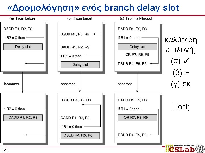
Αντιμετώπιση control hazards: 4 εναλλακτικές #4: Delayed Branches branch instruction sequential successor 1 sequential successor 2. . . . sequential successorn branch target if taken n 81 Branch delay μήκους n: οι εντολές εκτελούνται είτε το branch είναι Taken είτε όχι delay ενός slot: επιτρέπει απόφαση και υπολογισμό διεύθυνσης-στόχου στο 5 -stage pipeline χωρίς stalls
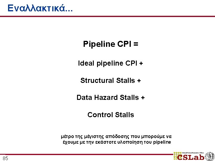
Εναλλακτικά. . . Pipeline CPI = υπερβαθμωτή εκτέλεση Ideal pipeline CPI + register renaming δυναμική εκτέλεση loop unrolling static scheduling, software pipelining 86 προώθηση Structural Stalls + Data Hazard Stalls + Control Stalls πρόβλεψη διακλαδώσεων υποθετική εκτέλεση delayed branches, branch scheduling
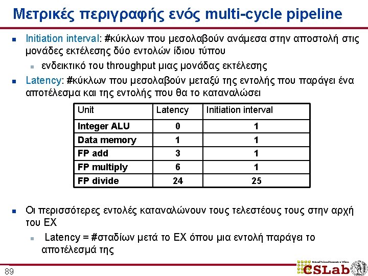
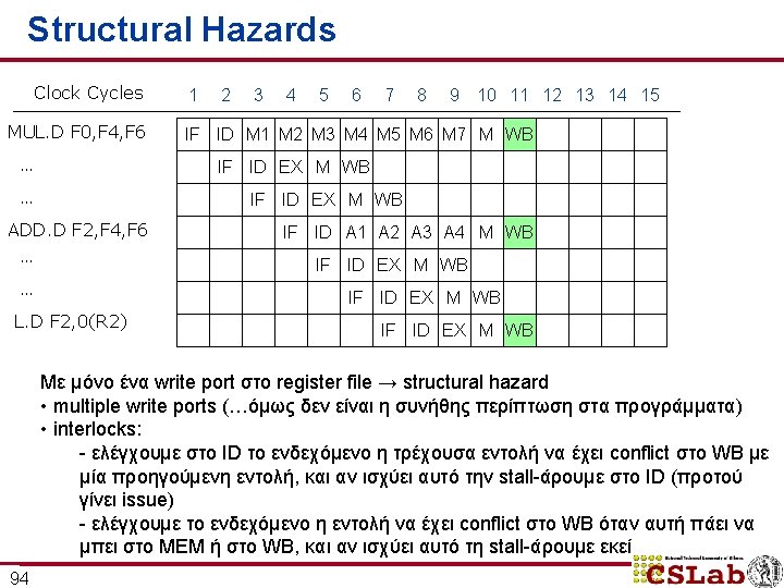
Παράδειγμα Clock Cycles MUL. D ADD. D L. D S. D 91 1 2 3 4 5 6 7 8 9 10 11 12 13 14 15 16 17 18 IF ID M 1 M 2 M 3 M 4 M 5 M 6 M 7 M WB IF ID A 1 A 2 A 3 A 4 M WB IF ID EX M WB
RAW hazards και αύξηση των stalls Clock Cycles L. D F 4, 0(R 2) 1 2 3 5 6 7 8 9 10 11 12 13 14 15 16 17 18 IF ID EX M WB MUL. D F 0, F 4, F 6 IF ID ADD. D F 2, F 0, F 8 IF S. D F 2, 0(R 2) 4 S M 1 M 2 M 3 M 4 M 5 M 6 M 7 M WB S ID S S S A 1 A 2 A 3 A 4 M WB IF S S S ID EX S S S • full bypassing/forwarding • η S. D πρέπει να καθυστερήσει έναν κύκλο παραπάνω για να αποφύγουμε το conflict στο ΜΕΜ της ADD. D 93 M WB
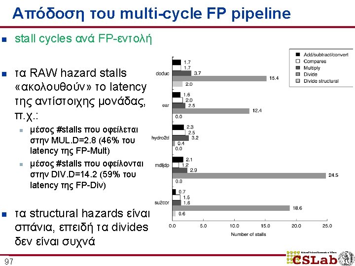
Απόδοση του multi-cycle FP pipeline n n n 98 stalls ανά εντολή + breakdown από 0. 65 μέχρι 1. 21 stalls ανά εντολή κυριαρχούν τα RAW hazard stalls ( «FP result stalls» )
Case-study: MIPS R 4000 Pipeline Instruction Memory RF Reg EX ALU IS IF DF DS Data Memory TC WB Reg Branch target and condition eval. n n n Deeper Pipeline (superpipelining): επιτρέπει υψηλότερα clock rates Fully pipelined memory accesses (2 cycle delays για loads) Predicted-Not-Taken πολιτική n n 99 Not-taken (fall-through) branch : 1 delay slot Taken branch: 1 delay slot + 2 idle cycles
Case-study: MIPS R 4000 Pipeline IF IS Instruction Memory complete ICache access 100 decode, register read, hazard checking, ICache hit detection RF 1 st half of DCache access EX Reg ALU PC selection, initiation of ICache access effective address calculation, ALU operation, branchtarget computation, condition evaluation DF Dcache hit detection DS Data Memory complete DCache access TC WB Reg register write-back
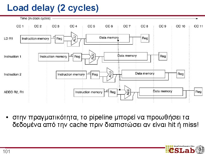
Branch delay (3 cycles) 102