INSTRUMENTATION CONTROL ENGG DEPTT GOVERNMENT POLYTECHNIC GANDHINAGAR BIOMEDICAL
")
INSTRUMENTATION & CONTROL ENGG. DEPTT. GOVERNMENT POLYTECHNIC, GANDHINAGAR BIOMEDICAL INSTRUMENTATION (361703)

1. Bio-electric Amplifiers 1. 1 Bioelectricity. 1. 2 Bioelectric amplifiers and their properties.

1. 1 Bioelectricity • Muscles and nerves are the two internal source which generate electric signal in human body. • Bioelectric potentials are generated at cellular level and source of these potential is ionic in nature. • A cell consist of ionic conductor separated from outer part by semi permeable membrane , through which some ions can pass. • Sodium (Na+), potassium(K+) and chloride (Cl-) are main ions involved in process of producing cell potentials.

• Cell membrane allows entry of K+ and Cl- but Na+ is not allowed and is surrounds across the membrane. • This results in concentration of sodium ion more on outside the cell. • A cell has negative charge along the inner surface of its membrane and positive charge along the outer portion. • The unequal charge distribution is result of electrochemical reactions and process occurring within living cell and potential measured is called resting potential.

• The cell in such condition is said to be polarized. A decrease in resting membrane potential difference is called depolarization. • The distribution of positively charged ions on outer surface and negatively charged ions inside cell membrane results in difference of potential across it and cell acts as biological battery. • The internal resting potential within a cell is -90 mv approx with reference to outside of cell. • When cell is excited or stimulated the outer side of cell membrane becomes negative with respect to interior. This process is called depolarization and cell potential changes to +20 mv approx.

• Reploarization takes place in short time when cell regains its normal state in which inside of membrane is again negative with respect to outside. • Repolarization is necessary in order to reestablish the resting potential. http: //t 3. gstatic. com/images? q=tbn: ANd 9 Gc. Qg 5 HEip 6 v 7 Zn. Xz. H 7 Fllo. Ii 9 SOz. Jk. NPoh 0 Ks. Eqk. AY 986 u. Sv-68 n

• The excitation wave in muscle causes its contraction. • Every contraction of muscle results in production if an electric voltage. • These voltages are called action potentials because they are generated by action of muscles. • After complete contraction, repolarization takes place resulting in relaxation of muscle and its returning to original state.

1. 2 Bioelectric Amplifiers and its properties Ref. Book Name : Handbook of Biomedical Instrumentation , Khandpur) • The bioelectric signals are in millivolt which are required to be amplified. • The following are the amplifiers used for it. �Differential amplifier �Instrumentation amplifier �Carrier amplifier �Chopper amplifier �Isolation amplifier

1. 2. 1 Differential Amplifier • These type have three input terminals out of which one is arranged at reference potential and other two are live terminals. • the two transistors with their respective collector resisters( R 1 and R 2) form a bridge circuit. • If the two resistors and characteristic of two transistors are identical, the bridge is balanced and potential difference- across the output terminal is zero.

V 1 Vout V 2 Rg http: //faculty. ksu. edu. sa/tuleimat/Documents/Part%202%20 Amplifiers%20%20 Applications. ppt

• If we apply signal at terminals 1 and 2 which are equal in amplitude but opposite in phase with reference to the ground. This signal is known as differential mode signal. • Because of this signal if the collector current of t 1 increases, the collector current of t 2 decreases by the same amount and viceversa. • This results in difference voltage between the two output terminals that is proportional to the gain of transistors.

• But if the signal applied to each input terminal is equal in amplitude and is in same phase called common-mode input signal. • The change in current flow through both transistors will be same, the bridge will remain balanced and voltage between output terminals will remain zero. • Thus, the circuit provides high gain for differential mode signal and no output for common mode signals.

1. 2. 2 Instrumentation Amplifier • Instrumentation amplifier is a precision differential voltage gain device. • It consist of 3 op-amps and 7 resistors. • The amplifier A 1 and A 2 works as a buffer amplifier. And A 3 will act as differential amplifer. • Basically, connecting a buffered amplifier to basic differential amplifier makes an instrumentation amplifier.

http: //www. ece. msstate. edu/courses/design/2007/autopilot/SD 2_final_document. pdf

• A 3 op-amp and its four equal R form a differential amplifier with gain of 1. • The variable resistor Rvar is varied to balance out any common mode voltage. • V 1 is applied to positive input terminal and V 2 to negative input terminal. • The output of both the op-amps is amplified and fed to A 3. • V 0 is proportional to difference between the two input voltages.

1. 2. 3 Carrier Amplifier • A carrier type of amplifier is used to obtain zero frequency response of dc amplifier and stability of capacitance coupled amplifier. • It consist of oscillator and capacitance amplifier. • The oscillator is used to energize transducer with an alternating carrier voltage. • Therefore output of transducer will be amplitude (AM) signal.

amplifier rectifier Strain gauge transducer Phase sensitive detector Carrier oscillator Direct writing recorder

• The modulated AC signal is then fed to multi- stage capacitance coupled amplifier. • The first stage produces amplification of AM signal. • The second stage only respond to signal frequency of carrier. • After amplification, signal is demodulated in phase- sensitive demodulated circuit. • This helps to extract amplified signal voltage after filter circuit. • The voltage produced by demodulator is given to recorder.

1. 2. 4 Chopper Amplifier • This type of amplifier make use of chopping device, which converts slowly varying direct current to an alternating form with amplitude proportional to input direct current and with phase dependent on polarity of original signal. • The alternating voltage is then amplified by ac amplifier whose output is rectified back to get an amplifier direct current. • This is done to reduce drift problem using for narrow bandwidth.

input c 1 2 nd stage amplifier output R 1 R 3 C 3 Low pass filter R 2 Ac amplifier demodulator R 2 C 2 oscillator

• The amplifier gets low dc offset voltage and bias current by chopping low frequency components if input signal then amplifying this chopped signal in ac amplifier A 1. • Output of ac amplifier is then demodulated. • The low frequency components are derived form input signal by passing it through low-pass filter. • The filter output is then amplified in second stage amplifier A 2. • The output is the differential amplification of high frequency and low

1. 2. 5 Isolation Amplifier • Isolation amplifier are used for providing protection against leakage currents. • They break the ohmic continuity of electric signals between input and output of amplifier. • Three methods are used in it 1. Transformer isolation 2. Optical isolation 3. Capacitive isolation

1. 2. 5. 1 Transformer isolation • It uses either frequency-modulated or pulse-width modulated carrier signal with 30 k. Hz as carrier signal. • It consist of internal dc to dc converter having 20 KHz oscillator, transformer, rectifier and filter to supply isolated power. http: //farm 1. static. flickr. com/119/311074942_ee 65522 dfb. jpg

1. 2. 5. 2 Optically isolated amplifier • Here isolation is achieved by optically. • A separate battery operated circuit supplies power to the patient circuit and signal of interest is converted into light by bight source LED. • The light falls on phototransistor on output side, which converts light signal into electrical signal. http: //farm 1. static. flickr. com/119/311074942_ee 65522 dfb. jpg

1. 2. 5. 3 Capactively coupled isolated amplifier • It uses digital encoding of input voltage and frequency modulation to send the signal across differential capactive barrier. • Separate power supply is needed on both sides of barrier. Input signal modulator demodulator Capacitive isolation Output signal

2. 0 Medical Electrodes and transducers: • 2. 1 ECG, EEG, EMG medical electrodes. • 2. 2 Working Principle of following Biomedical Transducers: − 2. 2. 1 Body Temperature transducers. − 2. 2. 2 Blood Pressure Transducer − 2. 2. 3 Blood Flow Transducer − 2. 2. 4 Pulse Transducers − 2. 2. 5 Respiration Transducer

2. 1 Electrodes for ECG Ref. Book Name : Handbook of Biomedical Instrumentation , Khandpur) 1. Limb electrodes: • They are rectangular or circular surface electrodes. • They are applied to the surface of the body with electrode jelly. • They offer 2 to 5 K Ω. • The electrodes are held in position by elastic strap. • They are called limb electrodes as they are best suitable for application in four limbs of body. http: //een. iust. ac. ir/profs/Behnam/Med. Eng. Princ/Electrodes_Ch% 205. ppt

2. Floating electrodes • The interface can be stabilized by use of floating electrodes in which metal electrode does not make direct contact with the skin. • The principle of this electrode is to eliminated movement artifact by avoiding any direct contact of the metal with skin. • The only conductive path between metal and skin is electrolyte paste or jelly which forms an electrolyte brigde.
")
Commonly Used Biopotential Electrodes Insulating package Double-sided Adhesive-tape ring Electrolyte gel in recess (b) (a) snap Metal disk Snap coated with Ag-Ag. Cl External Gel-coated sponge Plastic cup Plastic disk Foam pad Tack Reusable Disposable Dead cellular material Capillary loops. Germinating layer (c) Floating Electrodes http: //een. iust. ac. ir/profs/Behnam/Med. Eng. Princ/Electrodes_Ch%205. ppt

3. Pre gelled disposable electrode • The main design feature of these electrodes which helps in reducing the possibility of artifacts, drift and baseline wandering is the provision of high- absorbency buffer layer with isotonic electrolyte. • This layer absorbs the effect of movement of electrode in relationship to the skin and create polarization similar to half-potential. http: //een. iust. ac. ir/profs/Behnam/Med. Eng. Princ/Electrodes_Ch%205. ppt

• It consist if large disk of plastic foam material with silver plated disk on one side attached to silver-plated snap. • A lead wire with snap is then snapped on to the electrode and used to connect the assemble to monitoring system. • The silver plated disk serves as electrode and may be coated with Agcl layer. • A layer of electrolyte gel covers the disk. • The electrode side of foam is covered with an adhesive material that is compatible with skin.

4. Air jet ECG electrodes • Air jet electrodes are Ag-Agcl electrodes encased within a medical silicon cup bounded by skin - engaging rim. • The contact area is a layer of synthetic sintered carbon by titanium screw. • Ambient air is drawn to small compressor and passed to electrodes at constant of 3. 8 psi. • As the air passes through venturi air jets the electrodes [produce constant vaccum of 2 psi at contact.

• The constant vacuum allows electrodes to remain attached to body. • The system uses a compressor to pump ambient air into distribution box. • From the distribution box, ten pvc wires carry air and stainless lead wires to the air jet electrodes.

2. 1 Electrodes for EEG Ref. Book Name : Handbook of Biomedical Instrumentation , Khandpur) • Chloride silver disc mainly used for EEG. • Contact with scalp is made via electrolytic paste through washer. • A pad electrode which is made from silver rod belled out at the end and padded with sponge material. • It is screwed into an insulated mount and held in place on head with rubber cap. • Another type EEG electrodes consist of multiple fine chloride silver wires fixed in rigid plastic cup.

• The plastic cup is fixed to the scalp with an adhesive. • It is filled with jelly through a hole in top. • In this electrode , contact with tissue is made via electrolyte bridge so that jelly in contact with electrode metal is not distributed by scalp movement. http: //een. iust. ac. ir/profs/Behnam/Med. Eng. Princ/Electrodes_Ch%205. ppt

2. 1 Electrodes for EMG Ref. Book Name : Handbook of Biomedical Instrumentation , Khandpur) • Needle electrodes for EMG consist of fine insulated wires placed so that their tips are in contact with nerve , muscle or other tissue. • The remaining part of wire is covered with some form of insulation to prevent shorting. http: //een. iust. ac. ir/profs/Behnam/Med. Eng. Princ/Electrodes_Ch%205. ppt

• The wires are either surgically implanted by means of hypodermic needle, leaving the wire electrode in place. • With this type of electrode the metal electrolyte interface takes place between uninsulated tip of wire and the electrolytes of body. • The hypodermic needle is sometimes part of electrode. • The wires forming the electrodes are carried inside the needle which creates the hole necessary for insertion protects the wires and act as grounded shield. • A single wire inside the needles serves as unipolar electrode which measures potentials at point of contact with respect to some indifferent reference.

2. 2. 1 Body temperature transducers Ref. Book Name : Handbook of Biomedical Instrumentation , Khandpur) • The following transducers can be used to measure body temperature: 1. Thermocouples 2. Electrical resistance thermometer 3. Thermistors 4. Radiation thermometry

2. 2. 1. 1 Thermocouples • When two wires of different materials are joined together at either end , forming two junctions which are maintained at different temperatures, thermo- emf is generated causing a current flow around the circuit. this arrangement is called thermocouple. • The junction at higher temperature is termed as hot or measuring junction and other is lower temperature called cold or reference junction. http: //images. brighthub. com/61/D/61 D 7 EA 338 D 54 D 6291 D 91 FDBDBEBB 99 E 74 BA 0 F 5 E 1_large. jpg

• The thermal emf and current produced is proportional to the temperature difference existing between the junctions. • Therefore, we get temperature measurement by inserting one junction in or on the surface at medium whose temperature is to be measured and keeping other at lower and constant temperature. • Measurable emf is produced proportional to temperature difference between the two junctions. • The reference junction is held at 0 c inside a vacuum flask containing melting ice.

2. 2. 1. 2 Electrical resistance thermometer • The temperature dependence of resistance of certain metals makes it convenient to construct temperature transducer. • Platinum or nickel are used for measurement of skin, rectal and oesophageal temperature. • The measurement of resistance is carried out by using Wheatstone bridge. http: //sengerandu. files. wordpress. com/2011/06/image 005. gif

• The variable resistance made from constantan which has a very low temperature coefficient of resistance. • The measuring coil and its connecting leads are place in one arm of bridge circuit with dummy pair of leads connected in opposite arm. • In this way, changes in resistance of coil leads with ambient temperature are cancelled out by corresponding changes in compensating leads.

2. 2. 1. 3 Thermistors • Thermistors are oxides of metals like manganese, cobalt and nickel which have large negative temperature coefficient of resistance that is as resistance decreases temperature will increases. • Operational amplifier circuit may be used to measure the current in thermistor as function of temperature. • They are available as wafers required for applying to skin surface , rods which can be used for rectal , oral or similar insertions and tiny beads so small that they can be mounted at tip of hypodermic needle for insertion into tissues.

http: //cache. daylife. com/imageserve/0 emacdge. PAb. Qe/280 x 516. jpg

2. 2. 1. 4 Radiation thermometry • Any material placed above absolute zero temperature emits electromagnetic radiation from its surface. • The cooler the object the lower the frequency of emitted electromagnetic waves and less power emitted. • The detector used for measuring the emitted infrared radiations are thermopiles, pyroelectric sensors, photoconductive cells.
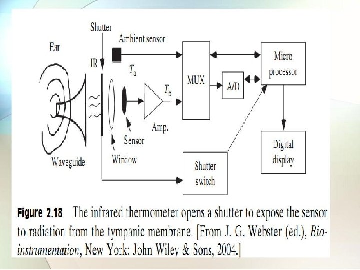

• A pyroelectric sensor is used to measure tympanic membrane temperature measurement. • A pyro electric sensor develops an electric charge that is funciton of its temperature gradient. • Temperature variation from infrared light striking the crystal changes the crystalline orientation, resulting in development of an electric charge.

2. 2. 2 Blood pressure transducer Ref. Book Name : Handbook of Biomedical Instrumentation , Khandpur) • The basic principle behind all the pressure transducer is that the pressure to be measured is applied to flexible diaphragm which gets deformed by the action of pressure exerted on it. • This motion of diaphragm is then measured in terms of an electrical signal • The diaphragm is a thin flat plate of circular shape, attached firmly by its edge to wall of containing vessel.

• The most commonly used pressure transducers which make use of diaphragm are of following types: �Capacitance manometer: in which diaphragm forms one plate of capacitor. �Differential transformer: where diaphragm is attached to core of differential transformer �Strain gauge: where the strain gauge bridge is attached to diaphragm.

2. 2. 2. 1 Capacitance manometer • In capacitance manometer a change in distance between the plates of capacitor changes its capacitance. • One of the plate is metal membrane separated from fixed plate by air. • Changes in pressure that change the distance between the plates thereby change the capacitance. • If this element is contained in high frequency resonant circuit the changes in capacitance vary the frequency of resonant circuit to produce a form of frequency modulation. • With suitable circuitry , blood pressure information can be obtained and recorded.

http: //www. omega. com/literature/transactions/volume 3/images/highfig 06. gif

2. 2 Differential transformer • In this device two secondary coils are wound oppositely and connected in series. • If the spring - loaded core is symmetrically positioned the induced voltage across one secondary coil opposes the voltage of other. • Movement of core changes this symmetry and the result is a signal developed across the combined secondary coil.

http: //accessscience. com/load. Binary. aspx? a. ID=9311&filename=704500 FG 0010. gif

2. 2. 2. 3 Strain gauge • The principle of strain gauge is that if a very fine wire is stretched its resistance increases. • If voltage is applied to the resistance the resulting current changes with resistance variation according to ohm’s law. • Thus forces responsible for the strain can be reduced as function of current. http: //sub. allaboutcircuits. com/images/00432. png

• Four strain gauges are mounted on diaphragm or membrane and these resistance are connected to form a bridge circuit. • Initially all resistances are equal when no pressure or strain is applied. • The gauges are attached to the pressure diaphragm in such a a way that as the pressure increases two of them stretch while other two contract. • When pressure changes unbalance the bridge a voltage appears between output terminals proportional to the pressure.

2. 2. 3 Body flow transducer Ref. Book Name : Medical Instrumentation , John webster 1. Magnetic blood flow meter: • Magnetic blood flow meter are based on the principle if magnetic induction. • A permanent magnet or electromagnet placed around the blood vessel generate a magnetic field perpendicular to direction of blood flow. • The voltage induced in moving blood column is measured with stationary electrodes located on opposite sides of blood vessel and perpendicular to the direction of magnetic field.

http: //clinical. medicalengineer. co. uk/diagrams/elecflow. jpg

• In block diagram of blood flow meter , the oscillator is used a control signal to gate as well as to drive magnet. • Signals obtained from probes are passed to preamplifier and then to gate. • The gated detector makes the polarity of output signal reverse when flow direction reverse. • The flow pulses are obtained at output of gate detector which can be filtered to obtain average flow.

2. Ultrasonic blood flow meter: • In ultrasonic blood flow meter, a beam of ultrasonic energy is used to measure velocity of flowing blood. • This can be done by two methods: a) Transit -time method b) Doppler method

�In transit time, a pulsed beam is directed through a blood vessel at small angle and its transmit time is then measured. �A short pulse is transmitted alternately in the upstream and downstream directions. �The difference between upstream and downstream transit time is proportional to velocity of flowing blood.

�In Doppler type : oscillator operating at frequency of MHz excites a piezoelectric transducer. • This transducer is attached to the wall of blood vessel and sends ultrasonic beam with frequency into the flowing blood. • A small part of transmitted energy is scattered back and is received by second transducer arranged opposite side. • Because scattering occurs mainly as result of moving blood cells the reflected signal has different frequency due to doppler effect. • The doppler frequency is proportional to velocity of flowing blood.

http: //clinical. medicalengineer. co. uk/diagrams/ultrasound. jpg

2. 2. 4 Pulse transducer Ref. Book Name : Handbook of Biomedical Instrumentation , Khandpur) • The pulse transducer measures the volume of blood. • The method used for detection of pulse changes due to blood flow are: a) Electrical impedance changes b) Strain gauge c) Optical change

• In impedance method , volume changes in segment of limb are reflected as impedance changes. • These impedance changes are due to changes in conductivity of current path with each pulsation of blood. • Electrodes contact the skin through suitable electrolyte jelly or paste to form an electrode interface and to remove the effect of skin resistance. http: //www. usra. ca/files/images/generation. jpg

• In strain gauge method , volume change is measured as change in diameter at certain cross section of finger , toe or other segment of body. • Change in diameter is sensed through use of mercury strain gauge in which it consist of segment of small diameter elastic tubing wrap around the limb. • With each pulsation of blood that increases the diameter of the limb the strain gauge expands thus increasing its resistance.

• In optical method , the device operates on principle that volume changes in limb, result in changes in the optical density through and beneath the skin. • A light source in an opaque chamber illuminates small area of fingertip or other region to which transducer is kept. • Light scattered and transmitted through the capillaries of region is picked by photocell. • As capillaries fill with blood the blood density increases thereby reducing amount of light reaching the photocell. • The result causes resistance changes in photocell that can be measured on Wheatstone bridge.

2. 2. 5 Respiratory transducer Ref. Book Name : Handbook of Biomedical Instrumentation , Khandpur) • The following are used to measure the respiratory rate: 1. Displacement method 2. Thermistor method 3. Impedance pneumograph 4. Co 2 method

2. 2. 5. 1 Displacement method • The respiratory rate can be determined by changes in the thoracic volume. • These changes can be sensed by means of displacement transducer like strain gauge or variable resistance element. • The transducer is held by elastic band, around the chest.

www. vhlab. umn. edu/~bmen 3701/Documents/Biopac 8. pdf

• The respiratory movement result in resistance changes of strain gauges element connected as one arm of Wheatstone bridge circuit. • Bridge output varies with chest expansion and yields signals corresponding to respiratory rate. • Changes in the chest circumference can be detected by rubber tube filled with mercury. • With the expansion of chest during inhale, the rubber tube increases in length and thus resistance of mercury from one end of this tube to other changes.

2. 2. 5. 2 Thermistor method • Since air is warmed during its passage through lungs and the respiratory tract, there is temperature difference between inspired and expired air. • This temperature difference can be sensed by using thermistors placed in front of nostrils by means of suitable holding device. • In case the difference in temperature of outside air and that of expired air is small thermistors can be initially heated to some temperature and variation of its resistance with respect to respiration rate can be detected. • Exhalation causes cooling effect to thermistor temperature vary.

http: //www. vhlab. umn. edu/~bmen 3701/Documents/Biopac 8. pdf

2. 2. 5. 3 Impedance pneumograph • This is indirect method which gives relation between respiration rate and thoracic impedance change. • This method consist of high frequency current oscillator , which is passed to electrodes placed on surface of body and detecting the modulated signal. • The output from the oscillator is applied to two outer electrodes. • The frequency modulated signal is then amplified and given to demodulator circuit.

http: //www. zuniv. net/physiology/book/images/13 -2. jpg

2. 2. 5. 4 Co 2 method • The measurement is based on absorption property if infrared rays by gases like co 2. • When the infrared rays are passed through the expired air containing co 2, some of rays are absorbed by it. • There is proportion heat loss with rays the detector changes heat loss effect into electrical signal.

http: //www. capnography. com/images/Physics/IR. gif

• The detector has two identical portions separated by thin flexible metal diaphragm. • Because of absorption of co 2 in analysis cell beam falling on test side of detector is weaker than reference side. • The gas in reference side is more heated than test side. • As a result diaphragm is pushed slightly to analysis side of detector. • The infrared beams are chopped at 25 Hz and alternating signal which appears across detector is amplified and recorded.

3. 0 Electrocardiograph: • 3. 1 The ECG waveform. • 3. 2 The standard lead system. • 3. 3 Block Diagram and working principle of ECG • machine. • 3. 4 ECG preamplifiers • 3. 5 ECG machine faults and troubleshooting. • 3. 6 Cardiac stimulation and life support equipment • Defibrillators, Defibrillator circuits, Cardio-version • Pacemaker, pacemaker classification

3. 1 The ECG waveform Ref. Book Name : Handbook of Biomedical Instrumentation , Khandpur) • Each action potential in the heart originates near the top of right atrium at a point a called Sino atria (SA)node. • The pacemaker is group of specified cells that generate action potentials at regular rate. • To initiate the heart beat the action potentials generated by SA node propagate in all directions along the surface of both atria. • The wave front of activation travels parallel to surface of atria toward junction of atria and ventricles.

http: //www. sads. org. uk/heart. jpg
 node.")
• The wave terminates at point near center of heart called atriventricular(AV) node. • t this point some special fibers act as” delay line” to provide proper timing between action of atria and ventricles. • After delay line, the excitation spread to all parts of both ventricles by bundle of His. • The fibers in this bundle called purkinje fibers, which divide into two branches to initiate action potentials in two ventricles.

• 3 distinct waves are produced during cardiac cycle • P wave caused by atrial depolarization • QRS complex caused by ventricular depolarization • T wave results from ventricular repolarizat Fig 13. 24 http: //www. cerritos. edu/charbut/AP 201/ECG. ppt 13 -63

• The P wave represents depolarization of atrial muscles. • The QRS complex is combined repolarization of atria and depolarization of ventricles which occur simultaneously. • The T wave is the wave of ventricular repolarization, where as U wave is after potentials in muscle of ventricles. http: //server. oersted. dtu. dk/31610/images/ECGintervals 3. gif

3. 2 The standard lead system Ref. Book Name : Handbook of Biomedical Instrumentation , Khandpur) • Two electrodes placed over different areas of heart and connected to galvanometer will pick up the electrical currents resulting from potentials difference between them. • The resulting tracing of voltage difference at any two sites due to electrical activity of heart is called “LE D”. • The lead system is classified as: a) Bipolar leads b) Unipolar leads
 Lead II (RA - LL)")
Standard leads Bipolar leads Lead I (RA - LA) Lead II (RA - LL) Lead III (LA - LL)

Bipolar leads and Unipolar leads http: //t 2. gstatic. com/images? q=tbn: ANd 9 Gc. TFAX 5 c 5 Zyi. J 4 PTKEftgt 9 -Zmvf. Dru. Int. GD 7 r. IRw 8 d_CJA 6 Asepg. DWn. Poll. Pg

3. 3 Block diagram and working principle of ECG machine Ref. Book Name : Handbook of Biomedical Instrumentation , Khandpur) • The potentials picked up by patient electrodes taken to lead selector switch. • By means of capacitive coupling , the signal is connected to differential amplifier. • The amplified output is given to power amplifier which is push pull differential type. • The base of one input is driven by signal of preamplifier. • The base of other transistor is driven by feedback signal resulting from pen position and connected via frequency selective network.

• The output of power amplifier is fed to pen motor, which deflects the writing arm on paper. • Frequency selective feedback network is R-C network , which provides necessary damping of pen motor. • The auxiliary circuit provide 1 mv calibration signal and automatic blocking of amplifier during a change in position of lead switch. http: //1. bp. blogspot. com/_j. Q-v 9 Ik. Lys/TUAu. P 3 zv. Ei. I/AAAAAVM/0 Bw. Eoh. Ctf. Nk/s 1600/mice r. bmp. jpg

3. 4 ECG Pre amplifier Ref. Book Name : Handbook of Biomedical Instrumentation , Khandpur) http: //openeeg. sourceforge. net/doc/modeeg/images/amp_block_ diagram. gif

• Different signals obtained from RA, LA and RL is given to low-pass filter. • After filtration, high voltage and over voltage protection circuit is used so that amplifier can withstand large voltages during defibrillation. • The lead selector switch is used to drive required lead configuration and give it to dc amplifier. • A a dc level of 1 mv is given to amplifier by pushbutton for calibration of amplifier. • Isolation of patient circuit is obtained using low capacitance transformer whose primary winding is driven from 100 KHz oscillator. • The transformer secondary is used to obtain isolated power supply of 6 v for operating the devices.

http: //www. ti. com/graphics/blockdiagram_images/6 163. gif

3. 5 ECG machine faults and Troubleshooting Ref. Book Name : Handbook of Biomedical Instrumentation , Khandpur) 1) Interference from power line: This interference is due to: • Stray effect of alternating current on patient. • Because of alternating current fields due to loops in patient cable. • Loose contacts on patient as well as dirty electrodes. • Machine or patient is not properly grounded • Disconnected electrode. 2) Shifting of baseline: • A wandering baseline is due to movement of patient or electrodes. • It is also due to slow establishment of electrochemical equilibrium at electrode skin interface.

3. 6 Defibrillator circuit Ref. Book Name : Medical Instrumentation , John webster • The rapid spread of action potential over the surface of atria causes these two chambers of heart to contract together and pump blood through AV valves into ventricles. • After some time delay, ventricular muscles synchronously activated to pump blood. • A condition in which this necessary synchronization is lost is know as fibrillation. • Electric shock to the heart can be used to reestablish normal cardiac rhythm. • Electric machines that produce energy to carry out this function are know as defibrillator.

Defibrillator circuit http: //coep. vlab. co. in/userfiles/5/image/l 2_3. png

• In this circuit , a half wave rectifier driven by step up transformer is used to charge the capacitor. • The voltage to which capacitor is charged is determined by variable auto transformer in primary circuit. • The capacitor is to discharge when electrodes are placed on body by changing the switch position. • The capacitor discharged through electrodes, delivering the energy. • Inductor is used to shape the wave in order to eliminate a sharp, undesirable current spike.

Cardio version Pacemaker Ref. Book Name : Medical Instrumentation , John webster • The rhythm beating of heart is due to triggering pulses that originate in area of right atrium called SA node. • In abnormal condition, this natural pacemaker unable to function or triggering pulse does not reach the heart muscle because of blocking by damaged tissue, the synchronization gets disturbed. • By giving external electrical stimulation impulses to heart muscle, it is possible to regulate the heart rate. • These impulses are given by electronic instrument called “Pacemaker”

Classification of Pacemaker Fixed rate On demand

Fixed rate Pacemaker • The pulse generator are fixed rate of asynchronous device that produce pulses at fixed rate and independent of any natural cardiac activity. Pulse output circuit Lead wires • The power supply is necessary to supply energy to the pacemaker circuit. oscillator • The oscillator establishes the pulse rate for pacemaker, which is given to pulse output circuit that provides stimulating pulse to the heart. • This pulse is conducted along lead wires to cardiac electrodes. Power supply electrodes

On demand Pacemaker • The demand pacemaker are synchronous type pulse generator. • After each stimulus, the Output circuit timing circuit resets itself and wait for interval to provide next stimulus. • If during the intervals a natural beat occurs in the ventricle, the feedback circuit detects QRS of ECG signal from electrodes and amplifies it. • The signal is used to reset the Timing circuit Reset circuit Electrodes

4. 0 Electroencephalograph • 4. 1 Electro-encephalography. • 4. 2 EEG electrodes and the 10 -20 electrode placement system • 4. 3 EEG amplitude and frequency bands. • 4. 4 Block Diagram and working principle of EEG Machine.
 •")
4. 1 Electroencephalography Ref. Book Name : Handbook of Biomedical Instrumentation , Khandpur) • The bioelectric potentials generated by neuronal activity of brain is called electroencephalography. • The interior of neuron is at potential of -70 mv relative to exterior. • When a neuron is exposed to stimulus above threshold, a nerve impulse seen as change in membrane potential is generated which spreads in the cell resulting in depolarization of cell. • The EEG signal can be picked up with electrodes either from scalp or directly from cerebral cortex which is normally 100 uv.

4. 2 EEG Electrodes and 10 -20 electrode placement system Ref. Book Name : Handbook of Biomedical Instrumentation , Khandpur) Nasion: point between the forehead and the skull Inion: bump at the back of the skull Location: Frontal, Temporal, Parietal, Occipital, Central z for the central line Numbers: Even numbers (2, 4, 6) right hemisphere, odd (1, 3, 5) left www-lehre. inf. uos. de/~fscharno/EEG. ppt
 www-lehre. inf. uos.")
The International 10/20 System (Ref: Handbook of Biomedical Instrumentation , Khandpur) www-lehre. inf. uos. de/~fscharno/EEG. ppt

• Electrodes are identified according to their position of head. �Fp: frontal polar �F: frontal �C: central �P: parietal �T: temporal �O: occipital �Z: midline elctrodes • Odd numbers refer to electrodes on left side of head and even numbers represent on right side. • The pattern of electrodes on the head and the channels they are connected is called montage.

4. 3 EEG amplitude and frequency bands • The basic EEG range is classified into following four bands for EEG analysis. 1) Delta : 0. 5 - 4 Hz. They occur in deep sleep and in serious organic brain disease. 2) Theta : 4 - 8 Hz. They are found in children and also occur during emotional stress in adults. 3) Alpha : 8 - 13 Hz. It is principle component of EEG and is an indicator of state of alertness of brain. 4) Beta : 13 - 22 Hz. They occur during intense mental activity.

EEG in the States of Vigilance Frequency Ranges Beta: 14 - 30 Hz Alpha: 8 - 13 Hz Theta: 5 - 7 Hz Delta: 1 - 4 Hz www-lehre. inf. uos. de/~fscharno/EEG. ppt

4. 4 Block diagram and working principle of EEG machine Ref. Book Name : Handbook of Biomedical Instrumentation , Khandpur) www-lehre. inf. uos. de/~fscharno/EEG. ppt

• Montage: A pattern of electrodes on the head and the channels they are connected to is called Montage. • Electrode montage selector: it a large panel containing switch that allow user to select which electrode pair will have signals subtracted from each other. • Preamplifier: every channel has individual , multistage, ac coupled, very sensitive amplifier with differential input and adjustable gain. • Sensitivity control: the overall sensitivity of EEG machine is gain of amplifier multiplied by sensitivity of writer. • Filters: EEG contain muscle artifacts due to contraction of scalp and neck muscles which are removed using low pass filter.

• Notch filter: tuned at 50 Hz so as to eliminate mains frequency interference. • High pass filter: the upper cut off frequency is controlled by it. • Writing part: the pen motors used in EEG machine have frequency response of 90 Hz. • Paper drive: this is provided by synchronous motor.

5. 0 Medical Ultrasonic equipments • 5. 1 Physics of Ultrasound • 5. 2 Ultrasonic foetal monitors, • 5. 3 Echoencephalography. • 5. 4 Echocardiography. • 5. 5. Working Principle and Diagram of color Doppler ultrasound machine

5. 1 Physics of ultrasound Ref. Book Name : Handbook of Biomedical Instrumentation , Khandpur) • Ultrasonic waves are sound waves have frequency range above 20 KHz. • Transmission of ultrasonic wave motion can be : �Longitudinal �Transverse �Shear • The longitudinal waves are used because it can be propagated in all types of media.

http: //www. ndted. org/Education. Resources/Community. College/Ultrasonics/Calib ration. Meth/Graphics/prop. gif
 Characteristic Impedance: It is defined as product of density of medium with velocity")
1) Characteristic Impedance: It is defined as product of density of medium with velocity of sound in same medium. it determines the degree of reflection and refraction at interface between two media. 2) Wavelength and frequency: ultrasonic waves pass only through a medium and transmitted as mechanical vibrations. for medical applications, 1 to 15 MHz are used. 3) Velocity of propagation: the velocity of propagation of wave is determined by density of medium , it is traveling through and stiffness of medium.

http: //www. ndted. org/Education. Resources/Community. College/Ultrasonics/Grap hics/Sound_Beam. jpg http: //www. antonineeducation. co. uk/physics_a 2/options/Module_6/Topic_5/US_
 Absorption of ultrasonic energy: in soft tissues, absorption coefficient depends on frequency and")
4) Absorption of ultrasonic energy: in soft tissues, absorption coefficient depends on frequency and therefore, for given amount of energy loss, lower frequency ultrasonic signal would travel more than higher frequency signal. 5) Resolution : it is defined as the ability of system to differentiate between closely relation structure. 6) Generation and detection of ultrasound: to generate and detect ultrasonic waves piezoelectric effect is used. materials with high mechanical Q factor are suitable as Transmitter where as those with low mechanical Q and high sensitivity as receivers.

5. 2 Ultrasonic foetal monitor Ref. Book Name : Medical Instrumentation , John webster • The Foetal heart rate is detected by ultrasonic using Doppler shift principle. • The Doppler shift based ultrasound foetal blood flow detector contain two piezo electric crystal. • The transmitting crystal emits ultrasound and back-scattered ultrasound is detected by receiving crystal. • The back scattered ultrasound frequency would be unchanged if the reflecting object is stationary. • If the reflecting object is moving, it would be foetal heart blood vessel, then back scattered frequency is higher as blood is approaching the probe and lower if it is moving away from the probe.

http: //cache. freescale. com/files/graphic/block_diagram/3680_BD 03_FHRM_TN. jpg

• Signal processing for FHR determination can be based either on detecting the foetal heart valve motion or an detecting the heart wall motion. • The oscillator produces 2 MHz frequency which is applied to transmitter crystal transducer. • The reflected beam is received by receiver crystal transducer and fed to amplifier and demodulator circuit. • The output of demodulator consist of Doppler frequency which is then amplified and rectified. • The rectified output is again filtered and given to one shot

5. 3 Echoencephalography Ref. Book Name : Medical Instrumentation , John webster • Echoencephalography is example of A-scan display ultrasonic imagining. • This type of scan offers one dimension information. • Imaging system consist of pulsed ultrasound piezoelectric crystal is used to transmit the signals and echoes are received through receiver. • The echo signals are applied to Y deflecting plates of CRT so that they are displayed as vertical blips as the beam is swept across the CRT.

http: //upload. wikimedia. org/wikipedia/commons/thumb/e/e 6/OCT _B-Scan_Setup. GIF/375 px-OCT_B-Scan_Setup. GIF

5. 4 Echocardiography Ref. Book Name : Medical Instrumentation , John webster • This is Doppler technique in blood flow measurement. • Pulsed Doppler ultrasound can be used to measure the velocity gradient across blood vessel as well as velocity of heart wall or specific valves in the heart. • Echocardiogram use M scan technique of ultrasound imagining. • If one of echo sources is a moving structure then the echo dots of light from that structure will also move back and front.

• If the dots are made to move with electronic sweep, from bottom to the top of the screen at pre-scaled rate of speed, the moving dots will trace out the motion pattern of moving structure. This display is known as M mode display. • The amount of vertical displacement is proportional to the strength of echo and distance along the horizontal trace represents the time of sound travel in tissue, thereby permitting accurate measurement of tissue depth between any two echo sources.

5. 5 Working principle and Block diagram of color Doppler ultrasound machine Ref. Book Name : Handbook of Biomedical Instrumentation , Khandpur) • Color Doppler ultrasound machine is based on measurement of local flow velocity in real time and display the surrounding structures in color coded form together with section scan of vessel walls. • The color can be red or blue indicates the direction of blood flow. • The intensity of color indicates velocity of flow.

• The probe is mechanically coupled to the position resolver which gives electrical output proportional to the movements of probe. • The position of spot on the CRT screen corresponds to that of sampling volume. • When sampling volume is within blood vessel, the spot is intensified and stored when Doppler signals are received. • A vessel is imaged by moving the probe over the skin surface and by adjusting the probe/sampling volume distance until the sampling volume has been swept through the section of vessel.

• The Doppler frequency shift is measure of size and direction of flow velocity. • The incident ultrasound is scattered by the blood cells and scattered wave is received by second transducer. • The frequency shift due to moving scatters is proportional to the velocity.

6. 0 Therapeutic instruments: • 6. 1 Working Principle & Block Diagram of electro-surgery machine • 6. 2 Working Principle & Block Diagram of Hemo-dialysis machine. • 6. 3 Principle of Electromyography, Muscle Stimulators.

6. 1 Working Principle & Block Diagram of electro-surgery machine Ref. Book Name : Medical Instrumentation , John webster • High frequency currents are used for cutting and coagulation. • For this surgical machine depends on the heating effect of electric current. • When high frequency current flows through the sharp edge of wire loop or the point of needle into the tissue, there is high concentration of current at this point. • The tissue is heated and get torn by boiling of cell fluid.

http: //t 0. gstatic. com/images? q=tbn: ANd 9 Gc. S 1 XIZJO_rvk. G 51 FF 3 M 77 IVEMF-d. Z 9 Prp. Oy. Nv. Mo 7 Np. DAMCu 5 Q 7 O 93 FJHb. Gz. A

• To produce high frequency power, power supply is applied to RF oscillator. • The high frequency signal produced by RF oscillator is modulated according to particular action required. • A function generator produces the modulation waveform according to mode selected by operator. • The RF power output is turned on or off by means of control circuit connected to hand or foot switch operated by surgeon. • The modulated signal is then amplified by power amplifier. • The output circuit couples the power generated to electrodes to

6. 2 Principle of Hemo-dialysis Machine Ref. Book Name : Handbook of Biomedical Instrumentation , Khandpur) • Dialyzer is the artificial kidney which replace the function of natural kidney , by removing waste products from blood. • An artificial kidney is a dialyzing unit which operates outside the patient’s body. • It receives blood from artery via plastic tubing. • The dialysate is electrolyte solution and dialysis takes place across membrane and then return of dialyzed blood to vein.

http: //www. baxter. com/images/patients_and_caregivers/therapies /renal/acute_kidney_treatment/crrt_diffusion. jpg

• The dialyzing membrane has holes through which waste produces from the blood are able to pass into the dialysate fluid from where they are washed away. • The dialysate fluid is free of waste product molecules and therefore they tend to distribute throughout the blood and dialysate. • This movement of waste product molecules from blood to dialysate results in cleaning of blood.

6. 2 Working Principle & Block Diagram of Hemodialysis machine. Ref. Book Name : Medical Instrumentation , John webster • The haem-diaylsis machine performs five function: �Mixes the dialysate. �Monitor the dialysate. �Pumps the blood and controls amount of anti- coagulants. �Monitors blood for presence of air and drip chamber pressure. �Monitor ultra-filtration rate.

http: //www. gml-dialyza. cz/Obrazky/hemodialysis. JPG

• There are basic units of machine: Exchanger and Dialysate delivery system. • The Exchanger chamber consist of dialysate and patient’s blood separated by semi - permeable membrane. • The waste product from blood are diffuse to dialysate, then thrown away. • The Dialysate is made up of water with various solutes. • It is pumped to dialysis chamber where it removes metabolic waste products and then discarded.

6. 3 Principle of Electromyography, Muscle Stimulators. Ref. Book Name : Medical Instrumentation , John webster • When an action potential occurs simultaneously in all muscle fibers in one motor unit, the resulting external electrical effect is small, spike-like potential which can be detected with electrodes placed on the surface of the muscle. • A surface electrical recording of the spiking activity derived from one or more motor units is called an electromyogram, or EMG. • During repeated firing of a motor unit, the amplitude and waveform of a motor unit spike tend to be constant. Spikes from different motor units may be distinguished from one another based on differences in amplitude and waveform. http: //www. ableweb. org/volumes/vol-21/12 -drewes. pdf

http: //www. ableweb. org/volumes/vol-21/12 -drewes. pdf

7. 0 Medical Laboratory Instrumentation and Monitoring • • 7. 1 Working Principle , Block Diagram and Applications of Blood Cell Counter, Blood p. H Analyzer and Autoanalyser. 7. 2 Monitoring instruments - Alarms, Respiration rate monitor, Heart beat monitor, Temperature monitor.

7. 1 Working principle of Blood counter Ref. Book Name : Medical Instrumentation , John webster • Blood is poor conductor of electricity and certain diluents are good conductors. • For a cell count, therefore blood is diluted and suspension is done through a small orifice. • By means of constant current source, a direct current is maintained between two electrodes located on both side of orifice. • As blood cell is carried through the orifice it displaces some of the conductive fluid and increases the electrical resistance between the electrodes. • A voltage pulse of magnitude proportional to cell volume is produced.

©J. Paul Robinson, Purdue University BMS 631 - LECTURE 1. PPT

7. 2 Blood p. H analyzer • The levels of oxygen and carbon dioxide which can be carried by haemoglobin are affected by the acidity [p. H] of the blood. • If a glass membrane separates two solutions of different hydrogen ion concentration a potential difference develops that is proportional to the hydrogen ion gradient between the two. • A potentiometric electrode is designed to measure the potential between the sample and a buffer solution. http: //www. frca. co. uk/article. aspx? articleid=100389

http: //www. frca. co. uk/images/cap 2. jpg

• A measuring silver/silver chloride electrode is encased in a bulb of special p. H-sensitive glass and contains a buffer solution that maintains a constant p. H. • This glass electrode is placed in the blood sample and a potential difference is generated across the glass, which is proportional to the difference in hydrogen ion concentration. • The potential is measured between a reference electrode (in contact with the blood via a semi-permeable membrane) and the measuring electrode. • Both electrodes must be kept at 37°C, clean and calibrated with buffer solutions of known p. H.

7. 2 Autoanalyzer Ref. Book Name : Medical Instrumentation , John webster • The autoanalyzer is sequentially measures blood chemistry and displays this on a graphic readout • This is accomplished by �Mixing �Reagent reagent �Reaction �Colorimetric measurement in continuous stream

faculty. ksu. edu. sa/Alhamwi/. . . /MLI-C 12 -autoanalyzer. pdf

• The sampler feeds the samples into the analyzer in time sequence. • A proportioning pump is used to meter the sample and reagent. • Mixing is achieved by injecting air bubbles. • The mixture is incubated while flowing through heated coils. • The air bubbles are removed and solution flows through chamber of colorimeter. • An electronic ratio recorder the output of reference and sample photocells.

7. 2 Monitoring instruments Ref. Book Name : Medical Instrumentation , John webster • The main objective of patient monitoring are: �Organizing and displaying information. �Displaying multiple parameters. �Processing the data to set alarms on abnormal conditions. �Providing information based on automated data.

http: //i. cmpnet. com/planetanalog/2010/08/C 0614 -Figure 1. gif

8. 0 Radiological Equipments. • 8. 1 Block diagram and operation of an X-Ray machine. • 8. 2 Types and uses of X-Ray machines. • 8. 3 Introduction to Tomography and Computerised Axial Tomography (CAT) technique.

8. 1 Block diagram and operation of an X-Ray machine. Ref. Book Name : Handbook of Biomedical Instrumentation , Khandpur) http: //www. daenotes. com/electronics/industrial-electronics/x-rays#axzz 1 i. D 6 PDxv. J

• High voltage source and high voltage transformer • High voltage source is responsible for providing high voltage to the H. V transformer for a decided time. The H. V transformer produces 20 KV to 200 KV at the O/P. • High voltage rectifier • This rectifier rectifies the high voltage produced by the H. V. T and supplies them to the anode of the X-ray tube. • Thermal overload detector • If the heat is exceed from a specified value, and then thermal over load detector is used to turn off system.

• Rotor control • Most of the X-ray tube anodes are rotated by an induction motor, in order to limit beam power at any spot and helps to cool the anode. • Pulse duration timer • The duration of the time must be very small so that the patient does not receive the excessive dose. • Aluminum Filter • The X-ray beam used in the medical field which contains a broad band of frequencies. To eliminate these effects Aluminum filter is used.

• Collimator • An external collimator placed between patient and filter to pass rays only on region of interest on body. • Diaphragm • X-rays inside the patient create x-ray scattering, which tends to burned the image to absorb the scattered x-rays and eliminate the burning of an image a lead grid is used which is called diaphragm. • Film and lead shield • The x-rays passed from the desired region of the patient body are made to strike on the film where they produce an image of the body soft and hard parts. A lead shield is use to collect the x-rays after striking on film.

8. 2 Types and uses of X-Ray machines. �Types of X-ray machine: CT Scanner : It takes two dimensional pictures of the individual and produces digital radiographs. Bone X-ray Machine: The x-ray tube is attached to a flexible arm that can be moved depending on what part of the body needs to be x-rayed. Linear Accelerator: The shoot intense beams of radiation to tumors to kill the cancer without affecting the rest of the body. Backscatter X-ray: Backscatter x-ray machines are used for airport security and baggage checks. http: //www. daenotes. com/electronics/industrial-electronics/xrays#axzz 1 i. D 6 PDxv. J

�Uses of X-ray Machine: • Detection of the fraction in bones. • Infection of lungs, kidneys and other injury. • Presence of Tumour. • X-rays are used for treatment for Tumour.
 technique Ref. Book Name")
8. 3 Introduction to Tomography and Computerised Axial Tomography (CAT) technique Ref. Book Name : Medical Instrumentation , John webster http: //www. profstelmark. com/1199_CT/7%20 Physical%20 principles%20 of%20 CT. ppt

• Computed Tomography is based on the x-ray principle; as x-rays pass through the body they are absorbed or weakened at differing levels. • Inside the CT machine is a semi-circular detector that measures the xrays strength. • This detector and the x-ray tube are mounted on a rotating frame that spins around the body of the patient taking roughly 1000 snapshots from different angles; every 360 degree rotation, a 'slice' is scanned. • Images can be reconstructed

9. 0 Miscellaneous • 9. 1 Theory of Macroshock and Microshock, Physiological effects of Electricity on the human body. • 9. 2 Line Isolation Systems.

9. 1 Theory of Macroshock and Microshock, Physiological effects of Electricity on the human body. Ref. Book Name : Medical Instrumentation , John webster • Macro shock: occurs when the human body becomes a conductor of electric current passing by means other than directly through the heart. This effect can readly occur with the use of medical electrical equipment as the natural resistance of the skin to current flow is often reduced or bypassed by electrodes and electorde paste or by invasion into mucous membrane. http: //www. medtek. ki. se/medicaldevices/album/Ch%203%20 Electricity%20 safety/slides/F%203 -1%20%20 Macroshock. jpg

• Micro shock: • Certain medical electrical procedures involve the introduction of an electrical conductor in direct contact with a ventricular heart muscle. • Micro shock may not be obvious as no outward and physically visible stimurus or contraction occurs. http: //www. medtek. ki. se/medicaldevices/album/Ch%203%20 Electricity%20 safety/slides/F%2 03 -3%20 Microshock. jpg

9. 2 Line Isolation Systems. Ref. Book Name : Medical Instrumentation , John webster • A line isolation monitor is used with such system that continuously monitors for the first ground fault, during which case it simply informs the operators to fix the problem. The single ground fault does NOT constitute a hazard! http: //users. rowan. edu/~polikar/CLASSES/ECE 404/Lecture 20. ppt

• Normally, when there is a ground-fault from hot wire to ground, a large current is drawn causing a potential hazard, as the device will stop functioning when the circuit breakers open. • This can be prevented by using the isolated system, which separates ground from neutral, making neutral and hot electrically identical. A single ground-fault will not cause large currents, as long as both hot conductors are initially isolated from ground!
- Slides: 162