
Instrument Rating Groundschool Session 2 Human Factors Aerodynamic




- Slides: 37
Instrument Rating Groundschool Session 2 Human Factors, Aerodynamic Factors, Flight Instruments (IFH Chapters 3&4)
Human Factors • The aspects of human factors of most concern to Instrument flight are sensory illusions related to the lack of visual reference encountered during flight. These fall broadly into two categories: • • Vestibular illusions occur when there is insufficient visual reference to provide the brain with a way to crosscheck information provided by the inner ear. Visual illusions occur when visual cues are misinterpreted, either consciously or unconsciously, by the pilot.
Vestibular Illusions • Vestibular illusions are caused by the brain misinterpreting fluid movement in the inner ear. This can lead to several distinct illusions. • Coriolis Illusion – occurs in a turn long enough for the fluid in the ear canal to move at the same speed as the canal. A movement of the head in a different plane may set the fluid moving and create the illusion of turning or accelerating on an entirely different axis. • Graveyard Spiral – Because an aircraft tends to lose altitude in turns unless the pilot compensates for the loss in lift, the pilot may notice a loss of altitude during a turn. The absence of any sensation of turning creates the illusion of being in a level descent. The pilot may pull back on the controls in an attempt to climb or stop the descent. This action tightens the spiral and increases the loss of altitude.
Vestibular Illusions (continued) • Somatogravic Illusion – A rapid acceleration, such as experienced during takeoff, stimulates the otolith organs in the same way as tilting the head backwards. This action creates the somatogravic illusion of being in a nose-up attitude, especially in situations without good visual references. • Inversion Illusion – An abrupt change from climb to straight-and-level flight can stimulate the otolith organs enough to create the illusion of tumbling backwards. • Elevator Illusion – An abrupt upward vertical acceleration, as can occur in an updraft, can stimulate the otolith organs to create the illusion of being in a climb. This is called elevator illusion. The disoriented pilot may push the aircraft into a nose-low attitude.
Visual Illusions • Runway Width Illusion – A narrower-than-usual runway can create an illusion the aircraft is at a higher altitude than it actually is. The pilot who does not recognize this illusion will fly a lower approach with the risk of striking objects along the approach path or landing short. A wider-thanusual runway can have the opposite effect. • Runway and Terrain Slopes Illusion – An upsloping runway can create an illusion the aircraft is at a higher altitude than it actually is. The pilot who does not recognize this illusion will fly a lower approach. Downsloping runways have the opposite effect. • Featureless Terrain Illusion – An absence of surrounding ground features, as in an overwater approach, over darkened areas, or terrain made featureless by snow, can create an illusion the aircraft is at a higher altitude than it actually is. This illusion, sometimes referred to as the “black hole approach, ” causes pilots to fly a lower approach than is desired.
Visual Illusions (continued) • False Horizon – A sloping cloud formation, and certain geometric patterns of ground lights can provide inaccurate visual information, or false horizon, for aligning the aircraft correctly with the actual horizon. The disoriented pilot may place the aircraft in a dangerous attitude. • Autokinesis – In the dark, a stationary light will appear to move about when stared at for many seconds. The disoriented pilot could lose control of the aircraft in attempting to align it with the false movements of this light called autokinesis. • Haze – Atmospheric haze can create an illusion of being at a greater distance and height from the runway. As a result, the pilot has a tendency to be low on the approach.
Visual Illusions (continued) • Fog – Flying into fog can create an illusion of pitching up. Pilots who do not recognize this illusion often steepen the approach quite abruptly. • Ground Lighting Illusions – Lights along a straight path, such as a road or lights on moving trains, can be mistaken for runway and approach lights. Bright runway and approach lighting systems, especially where few lights illuminate the surrounding terrain, may create the illusion of less distance to the runway. The pilot who does not recognize this illusion will often fly a higher approach. • Water Refraction – Rain on the windscreen can create an illusion of being at a higher altitude due to the horizon appearing lower than it is. This can result in the pilot flying a lower approach.
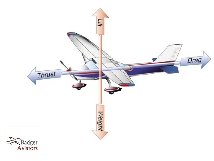
Four Forces of Flight • Lift is produced by the wings perpendicular to the longitudinal axis • Weight counteracts lift • Thrust propels the aircraft forward • Drag counteracts thrust • In level flight, all four forces are in equilibrium
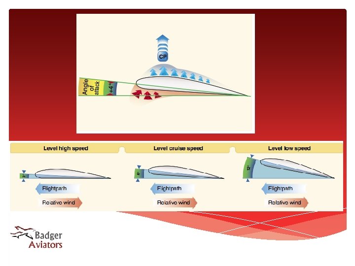
Lift • Wings create lift by creating a PRESSURE DIFFERENTIAL between the top and bottom surface. • The ANGLE OF ATTACK of a wing allows low pressure to form on the top surface while creating high pressure on the bottom surface. As air follows the top surface of the wing, it will be pulled downwards, helping to create low pressure on the top of the wing. Air on the bottom surface will be pushed downwards, creating an equal and opposite reaction upward as described by NEWTON’S THIRD LAW OF MOTION • As speed is reduced or weight increased, a higher angle of attack is required to produce enough lift. • At the critical angle of attack, a wing will STALL when the airflow separates from the top surface of the wing, allowing the low pressure area to dissipate.
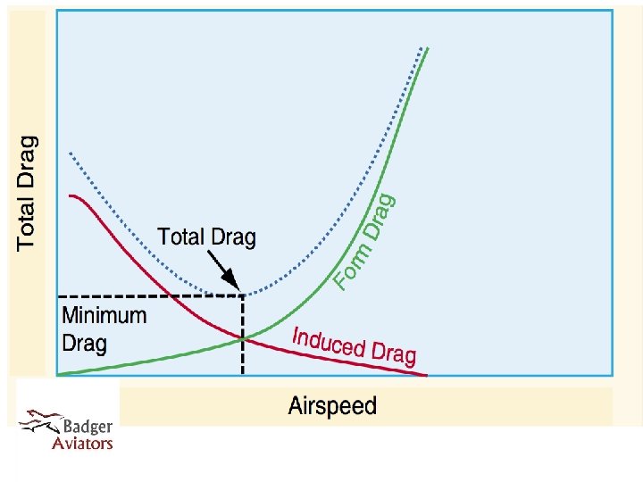
Drag • DRAG is the resistance the air exerts on an aircraft as it moves • INDUCED drag is created by the wing producing lift, and increases as angle of attack is increased. • PARASITE drag is caused by parts of the aircraft moving through the air, and increases as speed is increased. • INTERFERANCE drag is caused by airflow around different parts of the aircraft conflicting.
Thrust • Thrust propels an aircraft opposite the direction of force transmitted to the air. • Thrust can be produced by DIRECT REACTION as with a rocket or jet, or by a rotating PROPELLER • A propeller is in essence a wing rotating in a circle, which creates lift along the longitudinal axis. This is expressed as thrust. • Reaction thrust is expressed in pounds, while propeller driven aircraft express this in horsepower.
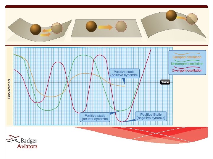
Stability • Stability is the tendency of an aircraft to fly straight and level • An aircraft that with POSITIVE stability will tend to remain straight and level, and/or return to that condition. An aircraft with NEGATIVE stability will tend to diverge from straight and level. • STATIC stability is an aircraft’s tendency to resist being disturbed from straight and level flight. • DYNAMIC stability is an aircraft’s tendency to return to straight and level flight after being disturbed from that condition.
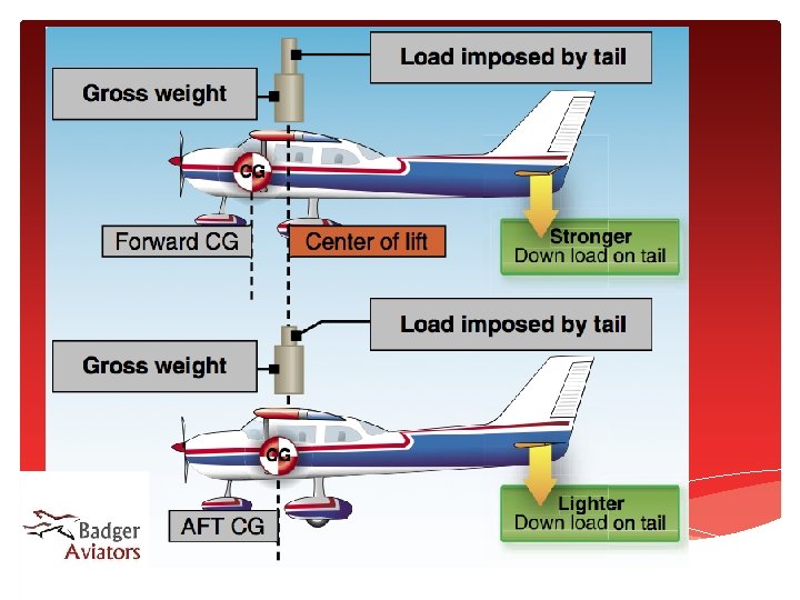
Stability (continued) • Stability can be expressed as being about any of the three axes. • Stability is created by opposition of forces. • The HORIZANTAL STABILIZER on the tail produces down force on the tail counteracting the lift of the wing. Aft center of gravity (CG) requires less down force and lessens stability about the lateral axis. • Stability about the longitudinal axis depends on the vertical location of the CG and center of lift, as well as the DIHEDRAL of the wing.
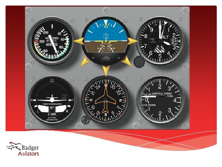
Flight Instruments • The standard six flight instruments are comprised of the • • • AIRSPEED INDICATOR (ASI) ATTITUDE INDICATOR (Artificial Horizon) ALTIMETER VERTICAL SPEED INDICATOR (VSI) DIRECTIONAL GYRO (DG) TURN COORDINATOR. • These are driven by three independent systems; The • • • PITOT/STATIC system (ASI, VSI, Altimeter) VACUUM system (Attitude Indicator, DG) ELECTRICAL system (Turn Coordinator)
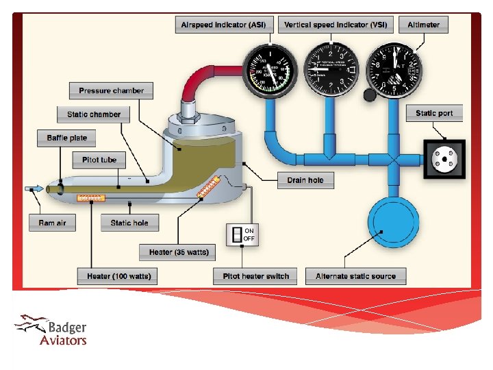
Pitot-Static System • The Pitot-Static system comprises five elements: • • • The PITOT TUBE senses ram air pressure created by the aircraft’s motion through the air. An electric heating element is often included to prevent ice accumulation. The STATIC PORT senses the static, or ambient, air pressure outside the aircraft The AIRSPEED INDICATOR compares Pitot pressure to static pressure and derive the aircraft’s airspeed. The ALTIMETER compares static pressure to a sealed reference chamber to derive the aircraft’s altitude The VERTICAL SPEED INDICATOR compares the static pressure to a reference chamber which has a calibrated leak, thus when the aircraft changes altitude, the pressure in the referance chamber lags behind creating a climb or decent indication. When the aircraft levels off, the pressure equalizes resulting in a neutral indication.
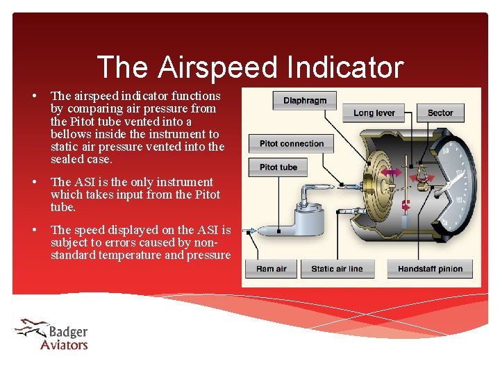
The Airspeed Indicator • The airspeed indicator functions by comparing air pressure from the Pitot tube vented into a bellows inside the instrument to static air pressure vented into the sealed case. • The ASI is the only instrument which takes input from the Pitot tube. • The speed displayed on the ASI is subject to errors caused by nonstandard temperature and pressure
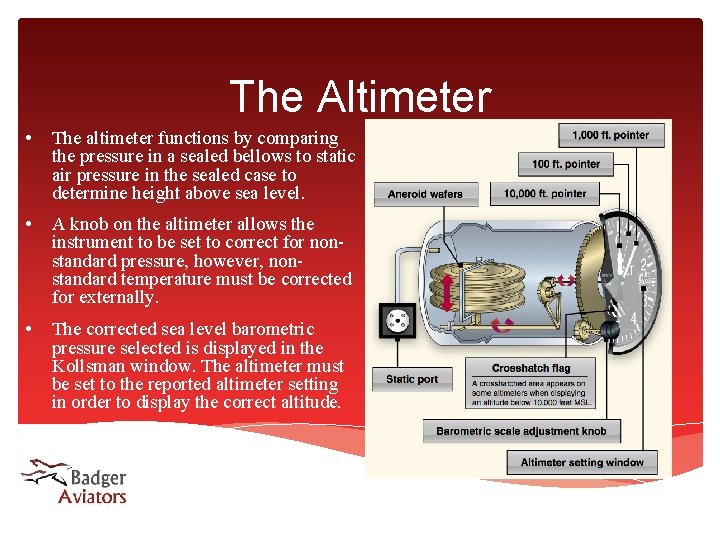
The Altimeter • The altimeter functions by comparing the pressure in a sealed bellows to static air pressure in the sealed case to determine height above sea level. • A knob on the altimeter allows the instrument to be set to correct for nonstandard pressure, however, nonstandard temperature must be corrected for externally. • The corrected sea level barometric pressure selected is displayed in the Kollsman window. The altimeter must be set to the reported altimeter setting in order to display the correct altitude.
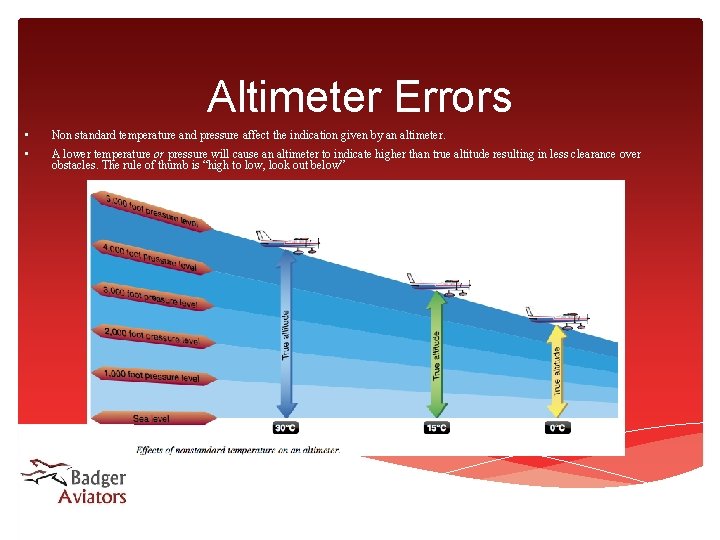
Altimeter Errors • Non standard temperature and pressure affect the indication given by an altimeter. • A lower temperature or pressure will cause an altimeter to indicate higher than true altitude resulting in less clearance over obstacles. The rule of thumb is “high to low, look out below”
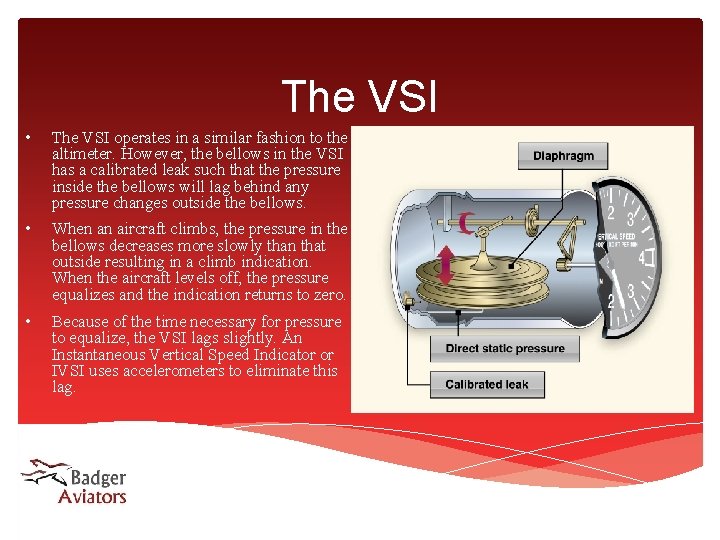
The VSI • The VSI operates in a similar fashion to the altimeter. However, the bellows in the VSI has a calibrated leak such that the pressure inside the bellows will lag behind any pressure changes outside the bellows. • When an aircraft climbs, the pressure in the bellows decreases more slowly than that outside resulting in a climb indication. When the aircraft levels off, the pressure equalizes and the indication returns to zero. • Because of the time necessary for pressure to equalize, the VSI lags slightly. An Instantaneous Vertical Speed Indicator or IVSI uses accelerometers to eliminate this lag.
Pitot-Static system failures • A blockage in the Pitot tube and, if installed, the drain hole, results in a fixed pressure in the Pitot tube line, thereby causing the Airspeed indicator not to react to changes in speed. Rather, As altitude increases static pressure decreases due to lower air density resulting in a higher airspeed indication. If the pitot tube is eqipped with a drain hole, and that hole is not plugged, the air pressure will equalize with ambient, and produce a zero airspeed indication. • A blockage in the static port will result in a fixed pressure in the static line irrespective of altitude. Airspeed will show small variations, but be unreliable, The altimeter will freeze in place, and the VSI will show a constant zero indication. Some aircraft are equipped with an alternate source of static air which draws air from inside the cabin, however airspeed and altitude will indicate higher when this source is used.
Vacuum System • The Vacuum system comprises five elements: • • • The VACUUM PUMP or, on some aircraft the VENTURRI, creates low pressure in oder to draw air through the system and spin gyroscopes. The REGULATOR ensures a constant flow of air through the system, evening out pressure variations due to pump speed. The SUCTION GUAGE allows the pilot to moitor the performance of the vaccum pump, and can aid in diagnosing failures of the vacuum system and/or gyroscopic instruments. The ATTITUDE INDICTOR (or Artificial Horizon) provides a direct indication of the aircraft’s angle of pitch and angle of bank. The HEADING INDICATOR (or Directional Gyro D. G. ) indicates the aircraft’s heading referenced to a gyroscope.
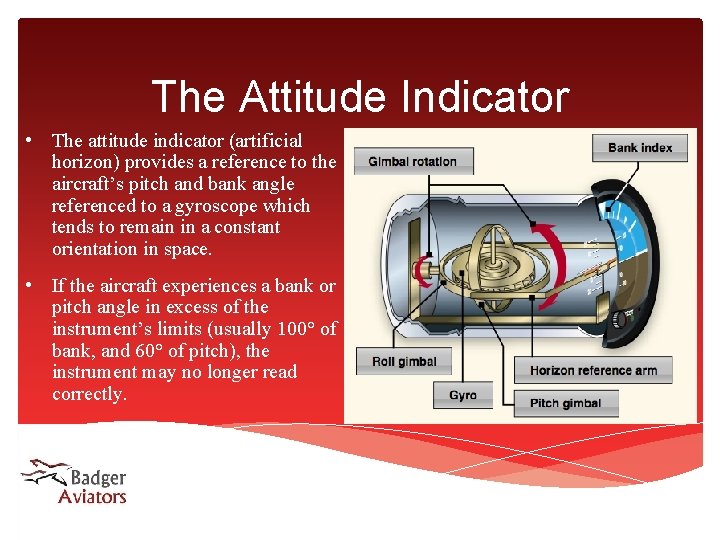
The Attitude Indicator • The attitude indicator (artificial horizon) provides a reference to the aircraft’s pitch and bank angle referenced to a gyroscope which tends to remain in a constant orientation in space. • If the aircraft experiences a bank or pitch angle in excess of the instrument’s limits (usually 100° of bank, and 60° of pitch), the instrument may no longer read correctly.
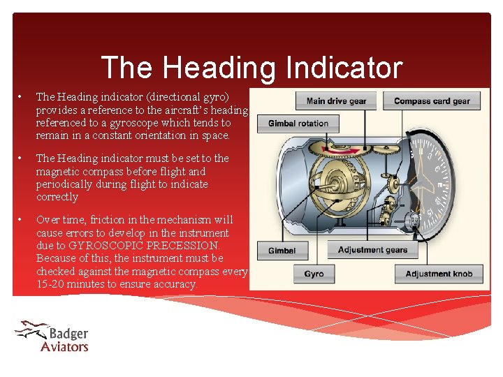
The Heading Indicator • The Heading indicator (directional gyro) provides a reference to the aircraft’s heading referenced to a gyroscope which tends to remain in a constant orientation in space. • The Heading indicator must be set to the magnetic compass before flight and periodically during flight to indicate correctly • Over time, friction in the mechanism will cause errors to develop in the instrument due to GYROSCOPIC PRECESSION. Because of this, the instrument must be checked against the magnetic compass every 15 -20 minutes to ensure accuracy.
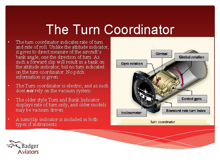
The Turn Coordinator • The turn coordinator indicates rate of turn and rate of roll. Unlike the attitude indicator, it gives to direct measure of the aircraft’s bank angle, one the direction of turn. As such a forward slip will result in a bank on the attitude indicator, but no turn indicated on the turn coordinator. No pitch information is given. • The Turn coordinator is electric, and as such does not rely on the vacuum system. • The older style Turn and Bank Indicator displays rate of turn only, and older models may be vacuum driven. • A turn/slip indicator is included in both types if instruments.
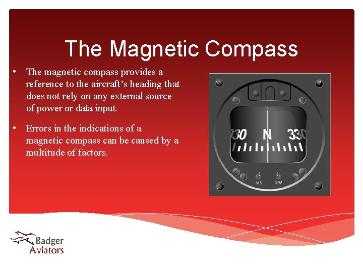
The Magnetic Compass • The magnetic compass provides a reference to the aircraft’s heading that does not rely on any external source of power or data input. • Errors in the indications of a magnetic compass can be caused by a multitude of factors.
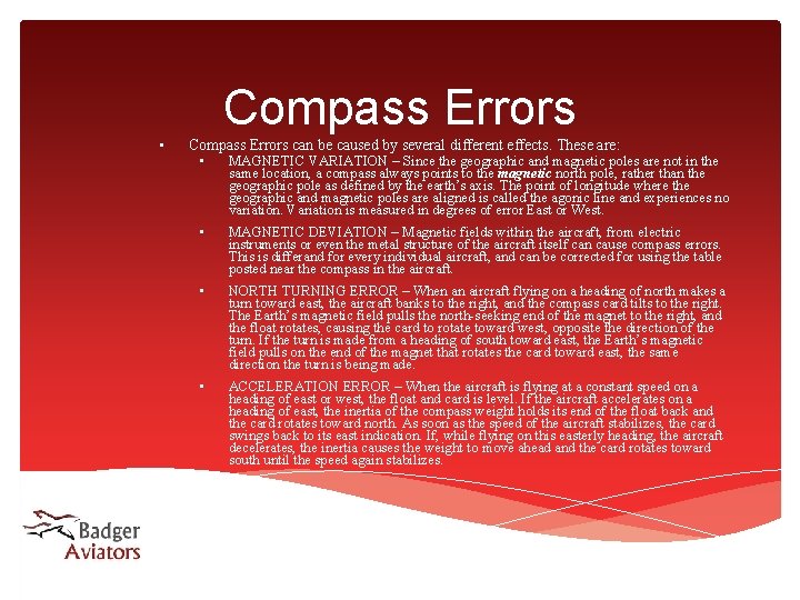
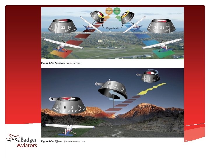
Compass Errors • Compass Errors can be caused by several different effects. These are: • MAGNETIC VARIATION – Since the geographic and magnetic poles are not in the same location, a compass always points to the magnetic north pole, rather than the geographic pole as defined by the earth’s axis. The point of longitude where the geographic and magnetic poles are aligned is called the agonic line and experiences no variation. Variation is measured in degrees of error East or West. • MAGNETIC DEVIATION – Magnetic fields within the aircraft, from electric instruments or even the metal structure of the aircraft itself can cause compass errors. This is differand for every individual aircraft, and can be corrected for using the table posted near the compass in the aircraft. • NORTH TURNING ERROR – When an aircraft flying on a heading of north makes a turn toward east, the aircraft banks to the right, and the compass card tilts to the right. The Earth’s magnetic field pulls the north-seeking end of the magnet to the right, and the float rotates, causing the card to rotate toward west, opposite the direction of the turn. If the turn is made from a heading of south toward east, the Earth’s magnetic field pulls on the end of the magnet that rotates the card toward east, the same direction the turn is being made. • ACCELERATION ERROR – When the aircraft is flying at a constant speed on a heading of east or west, the float and card is level. If the aircraft accelerates on a heading of east, the inertia of the compass weight holds its end of the float back and the card rotates toward north. As soon as the speed of the aircraft stabilizes, the card swings back to its east indication. If, while flying on this easterly heading, the aircraft decelerates, the inertia causes the weight to move ahead and the card rotates toward south until the speed again stabilizes.