Instrument landing automation system Autoland Automation landing system

 dimension 2 - Determinate zone of instrumental system")

 • Once established on an approach, the Autoland system or pilot")

 - A precision instrument approach and landing")

 is a ground-based instrument approach system that")


 antenna array is normally located")
 • GP antenna array is sited to one side")
")
")
")

 • is precision landing system originally intended to replace")

")


 functions the same as")

 is an all-weather aircraft landing system based on realtime")

 systems • describes a system that fully automates the landing phase")

- Slides: 28
Instrument landing automation system. Autoland
Automation landing system 1 -True Runway(RW) dimension 2 - Determinate zone of instrumental system
Two automatic landing systems have been developed: • A radar-beam type, detects the position and rate of change in position of the landing aircraft by means of a radar beam emitted from a ground derived - control complex. • A fixed-beam type, derives position and rate of change in position by instrumentation within the landing aircraft, but it makes use of Instrument Landing System (ILS) or Microwave Landing System (MLS) type equipment on the ground. In the aircraft are accelerometers (which may be part of an inertial navigation system) and a radio altimeter. Essential to both systems is an autopilot in the aircraft, commanded by a computer on the ground in the radar-beam system and by a computer in the aircraft for the fixed-beam system.
Decision altitude/height (DA/DH) • Once established on an approach, the Autoland system or pilot will follow the ILS and descend along the glideslope, until the Decision Altitude is reached. At this point, the pilot must have the runway or its approach lights in sight to continue the approach. • If neither can be seen, the approach must be aborted and a missed approach procedure will be performed. This is where the aircraft will climb back to a predetermined altitude and position. From there the pilot will either try the same approach again, try a different approach or divert to another airport. • Aborting the approach (as well as the ATC instruction to do so) is called executing a missed approach.
ILS categories
ILS categories • Category I (CAT I) - A precision instrument approach and landing with a decision height not lower than 200 feet (61 m) above touchdown zone elevation and with either a visibility not less than 800 meters (2, 625 ft) or a runway visual range not less than 550 meters (1, 804 ft). • Category II (CAT II) - A precision instrument approach and landing with a decision height lower than 200 feet (61 m) above touchdown zone elevation but not lower than 100 feet (30 m), and a runway visual range not less than 350 meters (1, 148 ft). • Category III (CAT III) is further subdivided – Category III A : • a) a decision height lower than 100 feet (30 m) above touchdown zone elevation, or no decision height; and • b) a runway visual range not less than 200 meters (656 ft). – Category III B : • a) a decision height lower than 50 feet (15 m) above touchdown zone elevation, or no decision height; and • b) a runway visual range less than 200 meters (656 ft) but not less than 50 meters (164 ft). – Category III C - with no decision height and no runway visual range limitations. A Category III C system is capable of using an aircraft's autopilot to land the aircraft and can also provide guidance along the runway surface.
Instrument landing system
• The Instrument Landing System (ILS) is a ground-based instrument approach system that provides precision guidance to an aircraft approaching and landing on a runway, using a combination of radio signals and, in many cases, high-intensity lighting arrays to enable a safe landing during instrument meteorological conditions (IMC), such as low ceilings or reduced visibility due to fog, rain, or blowing snow.
An approach plate for the ILS to runway 8 L at Atlanta Hartsfield Airport (ATL), Georgia
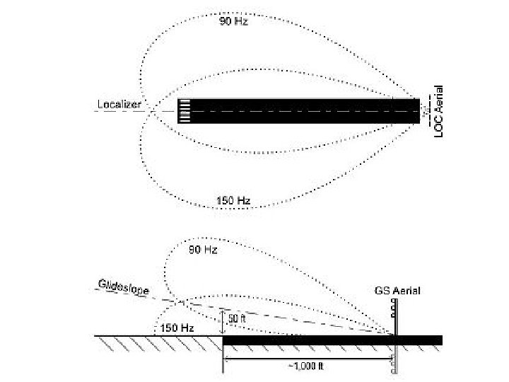
Principle of operation An ILS consists of two independent sub-systems: • one providing lateral guidance (Localizer) • the other vertical guidance (Glideslope or Glide Path) to aircraft approaching a runway. Aircraft guidance is provided by the ILS receivers in the aircraft by performing a modulation depth comparison.
• A localizer (LOC, or LLZ in Europe) antenna array is normally located beyond the departure end of the runway and generally consists of several pairs of directional antennas. Two signals are transmitted on one out of 40 ILS channels between the carrier frequency range 108. 10 MHz and 111. 95 MHz. One is modulated at 90 Hz, the other at 150 Hz and these are transmitted from separate but co-located antennas. Each antenna transmits a narrow beam, one slightly to the left of the runway centerline, the other to the right. • The localizer receiver on the aircraft measures the Difference in the Depth of Modulation (DDM) of the 90 Hz and 150 Hz signals. For the localizer, the depth of modulation for each of the modulating frequencies is 20 percent. The difference between the two signals varies depending on the position of the approaching aircraft from the centerline.
A glideslope or Glidepath (GP) • GP antenna array is sited to one side of the runway touchdown zone. The GP signal is transmitted on a carrier frequency between 329. 15 and 335 MHz using a technique similar to that of the localizer. The centerline of the glideslope signal is arranged to define a glideslope of approximately 3° above horizontal (ground level). The beam is 1. 4° deep; 0. 7° below the glideslope centerline and 0. 7° above the glideslope centerline. • Localizer and glideslope carrier frequencies are paired so that only one selection is required to tune both receivers.
HSI (left of centreline and below from glide path)
HSI (left of-centre line and at the glide path)
NPI (right of-centre line and at the glide path)
Antennas
The Microwave Landing System (MLS) • is precision landing system originally intended to replace or supplement the ILS. MLS has a number of operational advantages, including a wide selection of channels to avoid interference with other nearby airports, excellent performance in all weather, and a small "footprint" at the airports. • A widespread installation in the United Kingdom is currently underway, which included installing MLS receivers on most British Airways aircraft, but the continued deployment of the system is in doubt. NASA operates a similar system called the Microwave Scanning Beam Landing System to land the Space Shuttle.
Operational Functions • The system may be divided into five functions: Approach azimuth, Back azimuth, Approach elevation, Range and Data communications.
Approach azimuth guidance (Coverage Volume of the Azimuth station )
Coverage Volumes of the Elevation station
• The azimuth station transmits MLS angle and data on one of 200 channels within the frequency range of 5031 to 5091 MHz and is normally located about 1, 000 ft (300 m) beyond the stop end of the runway. • The azimuth coverage extends: Laterally, at least 40 degrees on either side of the runway centerline in a standard configuration. In elevation, up to an angle of 15 degrees and to at least 20, 000 ft (6 km), and in range, to at least 20 nm (37 km) • The elevation station transmits signals on the same frequency as the azimuth station. A single frequency is time-shared between angle and data functions and is normally located about 400 feet from the side of the runway between runway threshold and the touchdown zone. • Elevation coverage is provided in the same airspace as the azimuth guidance signals: In elevation, to at least +15 degrees; Laterally, to fill the Azimuth lateral coverage and in range, to at least 20 nm (37 km)
Range guidance • The MLS Precision Distance Measuring Equipment (DME/P) functions the same as the navigation DME, but there are some technical differences. The beacon transponder operates in the frequency band 962 to 1105 MHz and responds to an aircraft interrogator. The MLS DME/P accuracy is improved to be consistent with the accuracy provided by the MLS azimuth and elevation stations. • A DME/P 200 channel is paired with the azimuth and elevation channel. • The DME/N or DME/P is an integral part of the MLS and is installed at all MLS facilities unless a waiver is obtained. This occurs infrequently and only at outlying, low density airports where marker beacons or compass locators are already in place.
Data communications • The data transmission can include both the basic and auxiliary data words. All MLS facilities transmit basic data. MLS data are transmitted throughout the azimuth (and back azimuth when provided) coverage sectors. Representative data include: Station identification, Exact locations of azimuth, elevation and DME/P stations (for MLS receiver processing functions), Ground equipment performance level; and DME/P channel and status. • MLS identification is a four-letter designation starting with the letter M. It is transmitted in International Morse Code at least six times per minute by the approach azimuth (and back azimuth) ground equipment. • Auxiliary data content: Representative data include: 3 -D locations of MLS equipment, Waypoint coordinates, Runway conditions and Weather (e. g. , RVR, ceiling, altimeter setting, wind, wake vortex, wind shear).
Local Area Augmentation System (LAAS) is an all-weather aircraft landing system based on realtime differential correction of the GPS signal. Local reference receivers send data to a central location at the airport. This data is used to formulate a correction message, which is then transmitted to users via a VHF data link. A receiver on an aircraft uses this information to correct GPS signals, which then provides a standard ILS-style display to use while flying a precision approach. The International Civil Aviation Organization (ICAO) calls this type of system a Ground Based Augmentation System (GBAS).
Principle of operation
Autoland (automatic landing) systems • describes a system that fully automates the landing phase of an aircraft’s flight, with the human crew merely supervising the process. • were designed to make landing possible in visibility too poor to permit any form of visual landing, although they can be used at any level of visibility. They are usually used when visibility is less than 600 meters RVR(runway visual range) and/or in adverse weather conditions, although limitations do apply for most aircraft
• The means for guiding and controlling aircraft from an initial approach altitude to a point where safe contact is made with the landing surface. Such systems differ from low-approach systems in three major respects: • They furnish not only guidance but control of the aircraft as well. • They furnish information on the aircraft's position with respect to the terrain below it, and the rate at which the landing surface is being approached. • They do not require the pilot to assume manual control near the ground.