
Instrument Interface FPGA David Clarino CINEMA Space Sciences



- Slides: 13
Instrument Interface FPGA David Clarino CINEMA Space Sciences Laboratory University of California, Berkeley TRIO-CINEMA 1 UCB, 2/08/2010
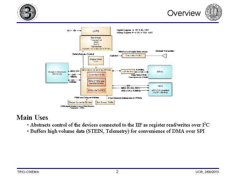
Overview Main Uses • Abstracts control of the devices connected to the IIF as register read/writes over I 2 C • Buffers high volume data (STEIN, Telemetry) for convenience of DMA over SPI TRIO-CINEMA 2 UCB, 2/08/2010
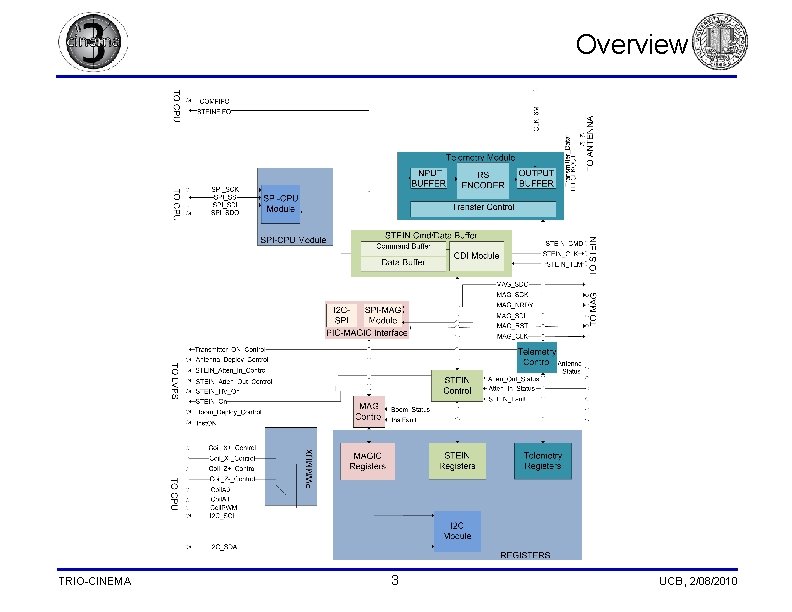
Overview TRIO-CINEMA 3 UCB, 2/08/2010
Overview MAGIC • • relays commands from CPU to control MAGIC ADC reads ADC data to register on IIF for CPU read STEIN • pulls data from STEIN and buffers it into blocks convenient for DMA Telemetry • • TRIO-CINEMA Frames CCSDS Source Packets into CCSDS Transfer Frames Reed-Solomon Encodes the Transfer Frame 4 UCB, 2/08/2010
CPU Interface Overview I 2 C Interface Address (Hex) • runs at 400 k. Hz • ds. PIC can command IIF by writing to/reading from registers • different size registers reflect IIF’s organization of data • Uses slave address as register address SPI Interface • DMA STEIN data from IIF, TLM data to 5 Length (bits) Telemetry Signals Page # 12 0 x 00 TLMSTART 8 TLMON 12 0 x 01 VCRD 8 VCRD 12 0 x 02 MCRD 8 MCRD 12 0 x 03 FRMBYTE 8 FRMBYTE 12 0 x 04 BFRBYTE 8 BFRBYTE 12 0 x 05 FRMPCKT 8 FRMPCKT 12 0 x 06 CLCW 32 CLCW 13 0 x 07 FRAMEID 16 FRAMEID 13 0 x 08 FRMDATA 16 FRMDATA 13 0 x 09 FRMHDWEN 8 MCSET, VCSET, IDSET, DATASET 13 0 x 0 A ANTARM 8 ANTARM 13 0 x 0 B ANTDEP 8 ANTDEP 13 0 x 0 C ANTSTAT 8 0 x 10 STEINCMD 24 STEINDCMD 14 0 x 11 STEINSTS 8 ATNIN, ATNOUT 14 0 x 12 STEINFLT 8 STEIN_Fault 14 0 x 13 STEINATN 8 STEINATN 14 0 x 14 STEINON 8 STEINON 15 0 x 15 STEINHV 8 STEINHV MAG 15 0 x 20 MAGCMD 8 MAGCMD 15 0 x 21 MAGDATA 24 MAGDATA 17 0 x 22 BOOMARM 8 BOOMARM 17 0 x 23 BOOMDEP 8 BOOMDEP 17 0 x 24 BOOMOUT MAGICFLT 8 BOOMOUT Inst_Fault 17 0 x 25 TRIO-CINEMA Name 8 ANTSTAT STEIN 14 14 15 18 UCB, 2/08/2010
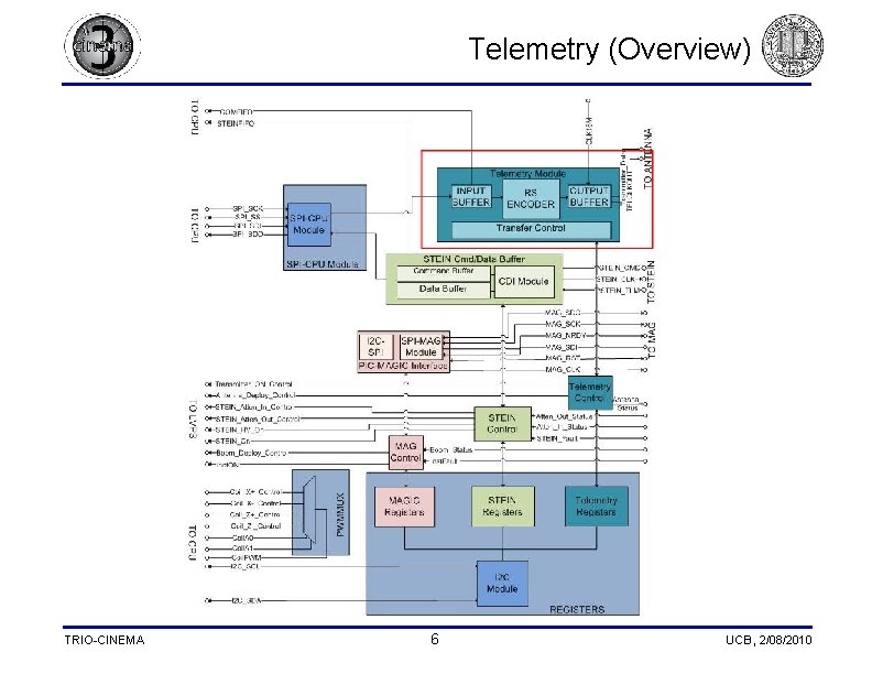
Telemetry (Overview) TRIO-CINEMA 6 UCB, 2/08/2010
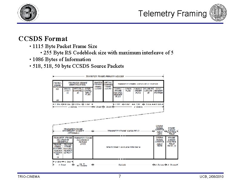
Telemetry Framing CCSDS Format • 1115 Byte Packet Frame Size • 255 Byte RS Codeblock size with maximum interleave of 5 • 1086 Bytes of Information • 518, 50 byte CCSDS Source Packets TRIO-CINEMA 7 UCB, 2/08/2010
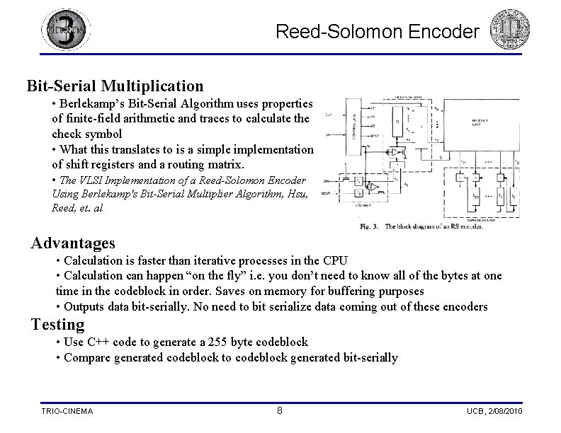
Reed-Solomon Encoder Bit-Serial Multiplication • Berlekamp’s Bit-Serial Algorithm uses properties of finite-field arithmetic and traces to calculate the check symbol • What this translates to is a simplementation of shift registers and a routing matrix. • The VLSI Implementation of a Reed-Solomon Encoder Using Berlekamp's Bit-Serial Multiplier Algorithm, Hsu, Reed, et. al Advantages • Calculation is faster than iterative processes in the CPU • Calculation can happen “on the fly” i. e. you don’t need to know all of the bytes at one time in the codeblock in order. Saves on memory for buffering purposes • Outputs data bit-serially. No need to bit serialize data coming out of these encoders Testing • Use C++ code to generate a 255 byte codeblock • Compare generated codeblock to codeblock generated bit-serially TRIO-CINEMA 8 UCB, 2/08/2010
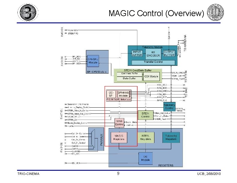
MAGIC Control (Overview) TRIO-CINEMA 9 UCB, 2/08/2010
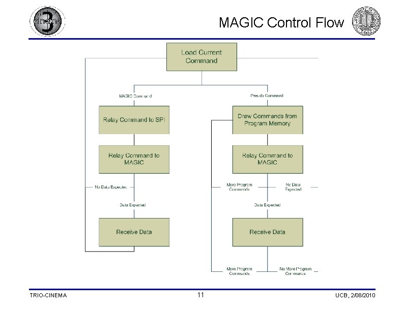
MAGIC Control (Overview) Interface • CPU writes commands and receives MAG Vectors over I 2 C • IIF writes commands and receives MAG Vectors from MAGIC over SPI Two Types of Vector Reads • X, Y, Z B-fields from either the outboard or inboard sensors • Outboard Temperature Read (Thermistor) • CPU polls at most 64 Hz ADC is relatively “dumb” • CPU/FPGA need to initiate read. • CPU issues pseudo commands that get translated to actual MAGIC commands • Advantages: a channel read will only be a single command from the viewpoint of the CPU. Since read is initiated by CPU, relatively easy for CPU to determine what kind of data is returned by MAG TRIO-CINEMA 10 UCB, 2/08/2010
MAGIC Control Flow TRIO-CINEMA 11 UCB, 2/08/2010
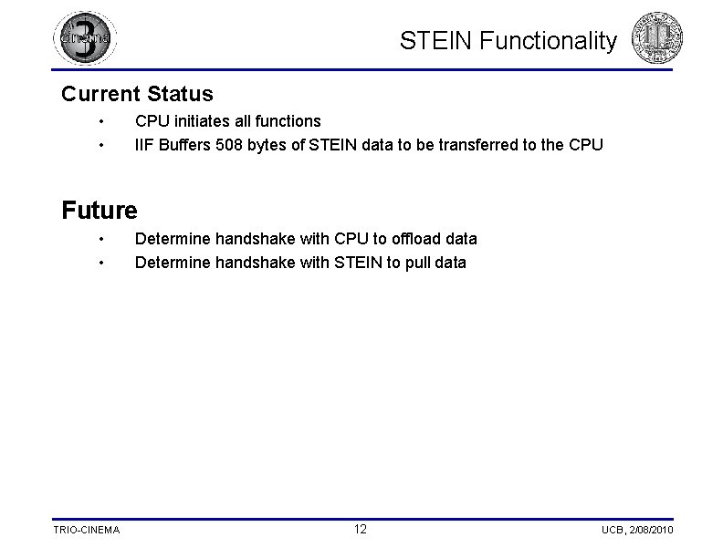
STEIN Functionality Current Status • • CPU initiates all functions IIF Buffers 508 bytes of STEIN data to be transferred to the CPU Future • • TRIO-CINEMA Determine handshake with CPU to offload data Determine handshake with STEIN to pull data 12 UCB, 2/08/2010
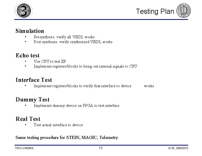
Testing Plan Simulation • • Presynthesis: verify all VHDL works Post-synthesis: verify synthesized VHDL works Echo test • • Use CPU to test IIF Implement registers/blocks to bring out internal signals to CPU Interface Test • Implement registers/blocks to verify that interface to device works Dummy Test • Implement dummy device on FPGA to test interface Real Test • Test actual interface to device Same testing procedure for STEIN, MAGIC, Telemetry TRIO-CINEMA 13 UCB, 2/08/2010