
Instrument Characterization Status Nischal Mishra David Flittner June
- Slides: 19
Instrument Characterization: Status Nischal Mishra David Flittner June 06, 2018 (757). 864. 7797 Nischal. Mishra@nasa. gov david. e. flittner@nasa. gov
Outline Ø Introduction Ø Results to-date • Detector and Electronics • Spectrometer properties: • Spectral Range, Spectral Bandpass, Spectral Sampling, Bandpass Shape, Spectral Smile and Key Stone • Image Quality Ø Road ahead Ø Summary 10/3/2020 Document Title 2
Introduction Ø TEMPO is a modest cost mission Ø Characterization is no exception Ø Testing at a variety of levels, i. e. sub-system and integrated system • All characterization data will be transferred to NASA/SAO servers. Ø Measure important characteristics and verify important assumptions, where possible 10/3/2020 Document Title 3
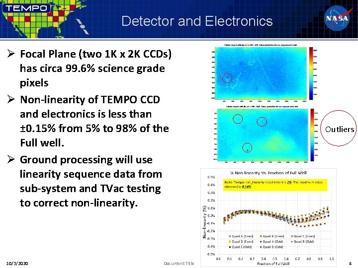
Detector and Electronics Ø Focal Plane (two 1 K x 2 K CCDs) has circa 99. 6% science grade pixels Ø Non-linearity of TEMPO CCD and electronics is less than ± 0. 15% from 5% to 98% of the Full well. Ø Ground processing will use linearity sequence data from sub-system and TVac testing to correct non-linearity. 10/3/2020 Document Title Outliers 4
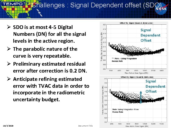
Challenges : Signal Dependent offset (SDO) Ø SDO is at most 4 -5 Digital Numbers (DN) for all the signal levels in the active region. Ø The parabolic nature of the curve is very repeatable. Ø Preliminary estimated residual error after correction is 0. 2 DN. Ø Anticipate refining estimated error with TVAC data in order to incorporate in the radiometric uncertainty budget. 10/3/2020 Document Title Signal Dependent Offset 5
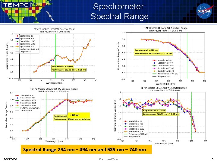
Spectrometer: Spectral Range < 540 nm Spectral Range 294 nm – 494 nm and 539 nm – 740 nm 10/3/2020 Document Title 6
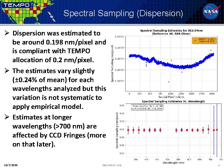
Spectral Sampling (Dispersion) Ø Dispersion was estimated to be around 0. 198 nm/pixel and is compliant with TEMPO allocation of 0. 2 nm/pixel. Ø The estimates vary slightly (± 0. 24% of mean) for each wavelengths analyzed but this variation is not systematic to apply empirical model. Ø Estimates at longer wavelengths (>700 nm) are affected by CCD Fringes (more on that later). 10/3/2020 Document Title 7
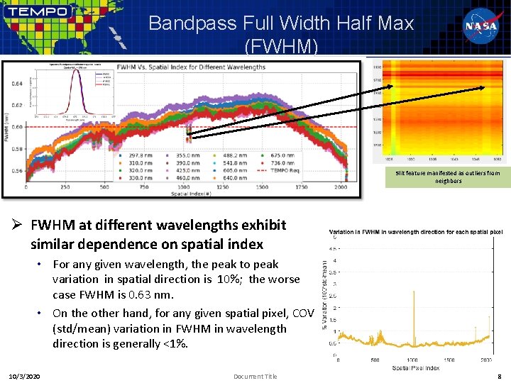
Bandpass Full Width Half Max (FWHM) Slit feature manifested as outliers from neighbors Ø FWHM at different wavelengths exhibit similar dependence on spatial index • For any given wavelength, the peak to peak variation in spatial direction is 10%; the worse case FWHM is 0. 63 nm. • On the other hand, for any given spatial pixel, COV (std/mean) variation in FWHM in wavelength direction is generally <1%. 10/3/2020 Document Title 8
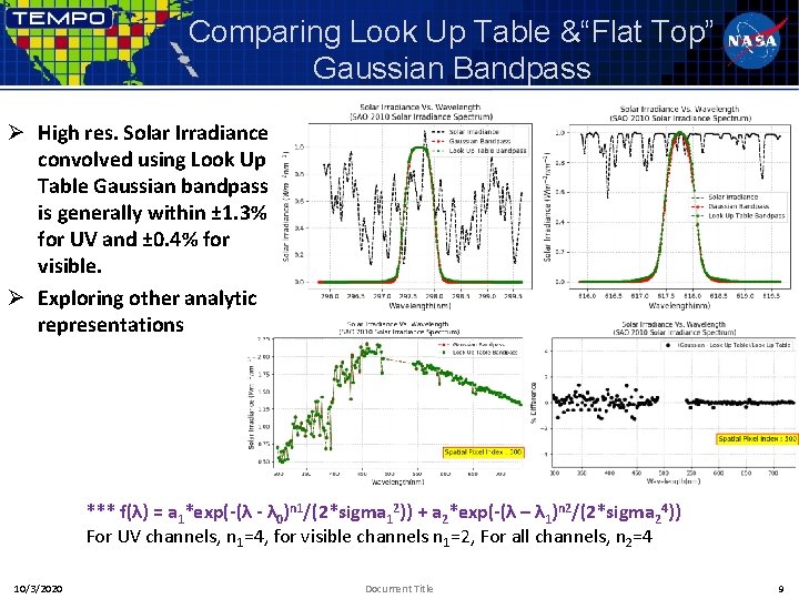
Comparing Look Up Table &“Flat Top” Gaussian Bandpass Ø High res. Solar Irradiance convolved using Look Up Table Gaussian bandpass is generally within ± 1. 3% for UV and ± 0. 4% for visible. Ø Exploring other analytic representations *** f(λ) = a 1*exp(-(λ - λ 0)n 1/(2*sigma 12)) + a 2*exp(-(λ – λ 1)n 2/(2*sigma 24)) For UV channels, n 1=4, for visible channels n 1=2, For all channels, n 2=4 10/3/2020 Document Title 9
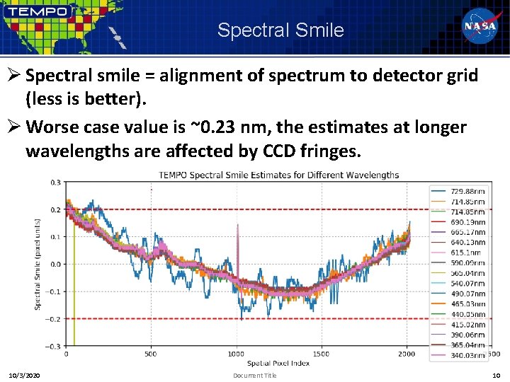
Spectral Smile Ø Spectral smile = alignment of spectrum to detector grid (less is better). Ø Worse case value is ~0. 23 nm, the estimates at longer wavelengths are affected by CCD fringes. 10/3/2020 Document Title 10
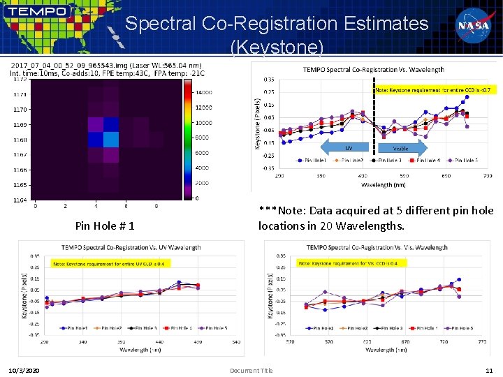
Spectral Co-Registration Estimates (Keystone) Pin Hole # 1 10/3/2020 ***Note: Data acquired at 5 different pin hole locations in 20 Wavelengths. Document Title 11
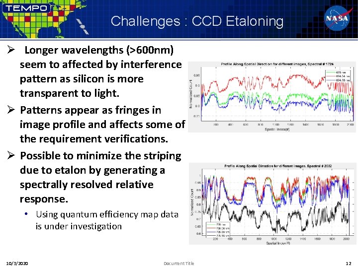
Challenges : CCD Etaloning Ø Longer wavelengths (>600 nm) seem to affected by interference pattern as silicon is more transparent to light. Ø Patterns appear as fringes in image profile and affects some of the requirement verifications. Ø Possible to minimize the striping due to etalon by generating a spectrally resolved relative response. • Using quantum efficiency map data is under investigation 10/3/2020 Document Title 12
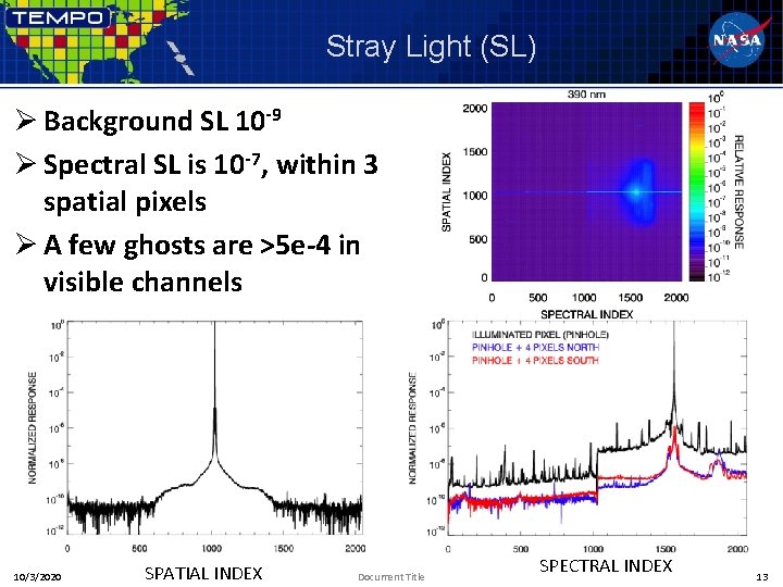
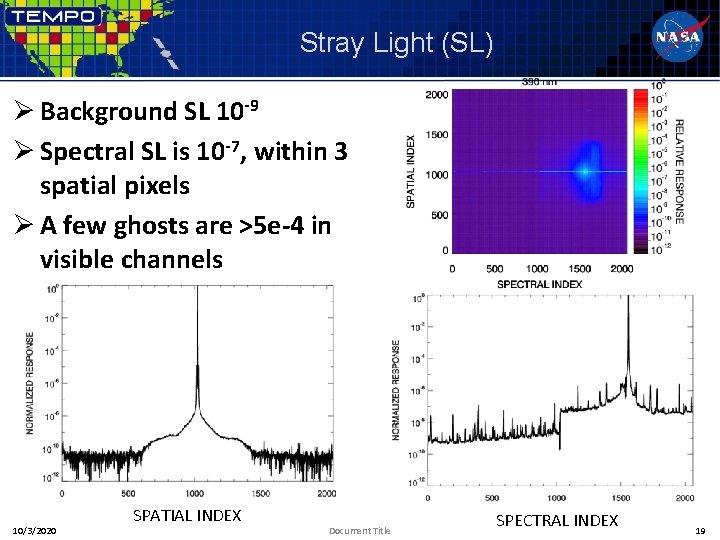
Stray Light (SL) Ø Background SL 10 -9 Ø Spectral SL is 10 -7, within 3 spatial pixels Ø A few ghosts are >5 e-4 in visible channels 10/3/2020 SPATIAL INDEX Document Title SPECTRAL INDEX 13
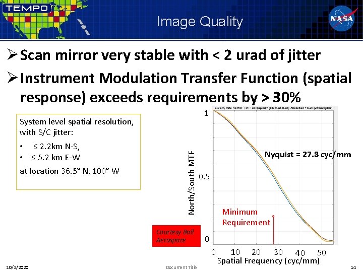
Image Quality Ø Scan mirror very stable with < 2 urad of jitter Ø Instrument Modulation Transfer Function (spatial response) exceeds requirements by > 30% 1 • ≤ 2. 2 km N-S, • ≤ 5. 2 km E-W at location 36. 5° N, 100° W North/South MTF System level spatial resolution, with S/C jitter: Courtesy Ball Aerospace Nyquist = 27. 8 cyc/mm 0. 5 Minimum Requirement 0 0 10/3/2020 Document Title 10 20 30 40 50 Spatial Frequency (cyc/mm) 14
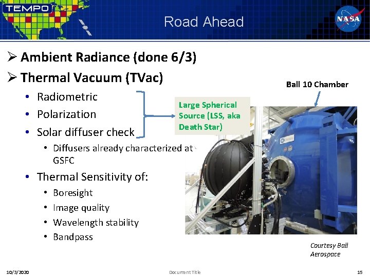
Road Ahead Ø Ambient Radiance (done 6/3) Ø Thermal Vacuum (TVac) • Radiometric • Polarization • Solar diffuser check Ball 10 Chamber Large Spherical Source (LSS, aka Death Star) • Diffusers already characterized at GSFC • Thermal Sensitivity of: • • 10/3/2020 Boresight Image quality Wavelength stability Bandpass Courtesy Ball Aerospace Document Title 15
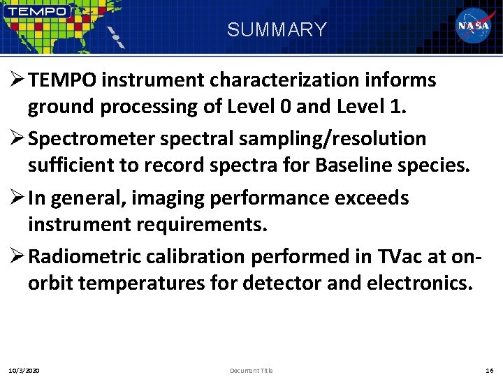
SUMMARY Ø TEMPO instrument characterization informs ground processing of Level 0 and Level 1. Ø Spectrometer spectral sampling/resolution sufficient to record spectra for Baseline species. Ø In general, imaging performance exceeds instrument requirements. Ø Radiometric calibration performed in TVac at onorbit temperatures for detector and electronics. 10/3/2020 Document Title 16
BACKUP
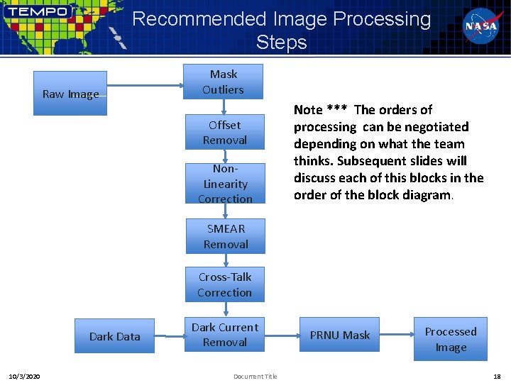
Recommended Image Processing Steps Raw Image Mask Outliers Offset Removal Non. Linearity Correction Note *** The orders of processing can be negotiated depending on what the team thinks. Subsequent slides will discuss each of this blocks in the order of the block diagram. SMEAR Removal Cross-Talk Correction Dark Data 10/3/2020 Dark Current Removal Document Title PRNU Mask Processed Image 18
Stray Light (SL) Ø Background SL 10 -9 Ø Spectral SL is 10 -7, within 3 spatial pixels Ø A few ghosts are >5 e-4 in visible channels 10/3/2020 SPATIAL INDEX Document Title SPECTRAL INDEX 19